EP1293309A1 - Handhabungsgerät, insbesondere zur Verwendung in Reinräumen - Google Patents
Handhabungsgerät, insbesondere zur Verwendung in Reinräumen Download PDFInfo
- Publication number
- EP1293309A1 EP1293309A1 EP02020510A EP02020510A EP1293309A1 EP 1293309 A1 EP1293309 A1 EP 1293309A1 EP 02020510 A EP02020510 A EP 02020510A EP 02020510 A EP02020510 A EP 02020510A EP 1293309 A1 EP1293309 A1 EP 1293309A1
- Authority
- EP
- European Patent Office
- Prior art keywords
- cavity
- gas
- handling device
- moving member
- base body
- Prior art date
- Legal status (The legal status is an assumption and is not a legal conclusion. Google has not performed a legal analysis and makes no representation as to the accuracy of the status listed.)
- Granted
Links
Images
Classifications
-
- B—PERFORMING OPERATIONS; TRANSPORTING
- B25—HAND TOOLS; PORTABLE POWER-DRIVEN TOOLS; MANIPULATORS
- B25J—MANIPULATORS; CHAMBERS PROVIDED WITH MANIPULATION DEVICES
- B25J15/00—Gripping heads and other end effectors
- B25J15/02—Gripping heads and other end effectors servo-actuated
- B25J15/0253—Gripping heads and other end effectors servo-actuated comprising parallel grippers
- B25J15/028—Gripping heads and other end effectors servo-actuated comprising parallel grippers actuated by cams
-
- B—PERFORMING OPERATIONS; TRANSPORTING
- B25—HAND TOOLS; PORTABLE POWER-DRIVEN TOOLS; MANIPULATORS
- B25J—MANIPULATORS; CHAMBERS PROVIDED WITH MANIPULATION DEVICES
- B25J19/00—Accessories fitted to manipulators, e.g. for monitoring, for viewing; Safety devices combined with or specially adapted for use in connection with manipulators
- B25J19/0075—Means for protecting the manipulator from its environment or vice versa
Definitions
- the invention relates to a manual handling device, in particular for use in clean rooms, with a body, with a recess in the body for receiving at least one displaceably mounted in the base body Movement member and with one in the body angeordenten drive, wherein the moving member by the Drive at least in sections from the body is feasible and due to the shift of the Movement member in the body for a gas volume available cavity changes volume.
- Such handling devices are suitable, for example from DE 196 04 649 C2 in the form of gripping or Clamping devices become known.
- the drive of the Handling equipment can be either pneumatic, hydraulically or electrically. Between the Drive and the moving member can be a transmission kinematics be arranged.
- the handling devices are suitable for Use in clean rooms therefore not, since not it is ensured that no particle emissions from them emanates. Basically, wear and abrasion occurs two mutually moving, touching each other Objects. From the wear or the abrasion results in the unwanted particle emission. Handling equipment to be used in the clean room must therefore be built so that no particles and also no lubricants can get into the clean room.
- the present invention is therefore the task to propose a handling device of which no Particle emission emanates and therefore for use in Clean rooms is suitable.
- This object is in a handling device of the above described type solved according to the invention that between the main body and the surface of the Main bodyqriosbaren portion of the movement member Sealing means are provided which, as a result of a shift of the moving member with enlargement of the cavity gas from the clean room into the cavity and reducing the size of the Cavity no gas from the cavity into the clean room let in and that the cavity over a Exhaust duct with the outside of the body vebunden is, with the exhaust duct with one from the clean room leading line can be connected, and where Blocking means for regulating the flow resistance in the exhaust duct and / or the line are provided, the due to a displacement of the moving member at Enlargement of the cavity no gas - and thus no Particles - let flow into the cavity and at Reduction of the cavity gas via the outlet channel or let out of the cavity via the line.
- the sealing means comprise between Basic body and the surface of the bodyq.2,000.00, a sealing valve-like switching Seals. These seals have valve properties, whereby they hold tightly when flowing from one side and let the gas flow through when coming from the other side. When enlarging the cavity in the body can consequently, gas will flow into the cavity. At reduction the cavity and the associated higher pressure within the body, the sealants seal so that no gas from the body flow into the clean room can.
- the Sealant a small gap between the body and the surface of the lead out of the body Section of the moving member include, wherein the gap forms a relatively high flow resistance for the gas.
- the gap forms a relatively high flow resistance for the gas.
- a further embodiment of the invention provides that the blocking means a check valve, in particular a Check valve, include.
- the check valve is in this case be interpreted that it with decreasing cavity or at increasing pressure within the body opens and Gas from the cavity in the exhaust duct or in the line can flow in.
- the blocking means via switching means in Dependence of the movement of the movement member and / or the Drive switched.
- the drive over a arranged in a transmission cavity gear with the Movement member coupled.
- a Connecting channel between the cavity and the Transmission cavity or between the exhaust passage and the Gear cavity provided.
- Such a Connecting channel has the advantage that a in the Transmission cavity changing gas volume over the Exhaust duct or the line can be discharged.
- Another advantageous embodiment of the invention characterized by the fact that the drive one-sided Gasbeetzschlagbaren, in a cylinder chamber axially slidable, via a piston rod with the Moving member coupled piston includes, due to the Gasbeauschlagung the cavity is reduced.
- a Such a configuration has the advantage that at Gas supply due to the decreasing Cavity gas from the body via the exhaust duct and the opened blocking means can flow out. If the pneumatic drive has a leak, i. if during gas loading, the gas enters the cavity of the Body flows, the gas does not escape from the Base body, but it flows through the exhaust duct.
- the invention provides be that the non-gasbeetzschlagbare side of the piston can be pressurized via a spring element.
- the Enlarging the cavity is therefore via a Spring force.
- a spring element can, for example be a spiral or a leaf spring.
- Another embodiment is characterized that the exhaust duct is coupled to a vacuum generator is.
- the vacuum generator can in the cavity or creates a negative pressure in the recess of the body be prevented, which additionally prevents that from the Basic body particles can enter the clean room.
- the vacuum generator acts on the Cavity with negative pressure only when the cavity reduced due to the displacement of the moving member.
- a gripping or Clamping device in particular a two-finger parallel gripper or a three or more finger centric gripper be, whereby the base jaws of the gripping or clamping device forms the moving member.
- the handling device a Linear drive is, with piston rods and / or Guide rods of the linear drive the moving member form.
- the object mentioned above is also by a Method of operating one above described handling device solved that thereby indicates that a controller depends on the blocking means from the movement of the moving member and / or the Drive switches so that the blocking means open are when the cavity due to the displacement of the Movement member are reduced and closed, if the cavity increases.
- a further development of the method is characterized by that the vacuum generator is actuated via the control unit and then the cavity is subjected to negative pressure, when the cavity due to the displacement of the Movement member downsized.
- the inventive method has the advantage that it is ensured that during the operation of the Handling device no particles from the Handling device can escape into the clean room.
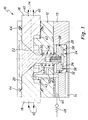
- Figures 1 and 2 show a first embodiment of a Handling device according to the invention in the form of a two-finger parallel gripper device 10.
- the gripping device 10th is intended for use in clean rooms, which is why the gripping device 10 emanating no particle emission may.
- the gripping device 10 has a base body 12, in The two movement members in the form of two along a line 14 axially movable mounted base jaws 16th and 18 are located.
- the base jaws 16, 18 are in one Recess 20 of the body 12 is arranged.
- the Base jaws 16, 18 are also facing each other Pages about a gear in the form of a known Schrägzuges or wedge hook 22 with a drive 24th coupled.
- the drive 24 includes one in a cylinder 26 slidably mounted piston 28, the piston rod 30 is connected to the diagonal pull 22.
- the cylinder 26 is arranged in a transmission housing section 13.
- the piston 28 is on its side facing away from the piston rod 30 side via a pressure chamber 32 with a fluid, and in particular with air, pressurizable. This is one of the Outside of the main body 12 to the pressure chamber 32nd extending pressure channel 34 is provided.
- On the Pressure chamber 32 side facing away from the piston 28 via a pressure spring 36 which is supported on the main body 12 with force.
- the existing within the body 12 cavity 42nd is via an exhaust passage 46 with the outside of the Main body connected to the exhaust passage 46 with a from the clean room leading, not shown, line connected is.
- an exhaust passage 46 In the exhaust passage 46 and the line is a schematically indicated check valve 48th intended.
- the exhaust passage 46 is also over a Connecting channel 50 with the not gasbeetzschlagten Piston space or the transmission or the compression spring 36th receiving gear cavity 52 connected.
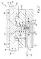
- FIG. 2 shows the entry situation of the base jaws 16 and FIG. 18.
- the pressure chamber 32 with Gas pressure applied causing the piston 28 against the Spring force in the direction of arrows 54 moves.
- the base jaws 16 and 18 in the direction the arrows 56 retracted.
- Due to the lock valve-like trained sealing rings 44 can not gas from the Base 12 along the base jaws 16 and 18 from the Exit gripping device 10. Rather, that opens Lock valve 48 due within the gripping device 10 resulting slight overpressure.
- gas can from the Gripping device 10 via the exhaust duct 46 and the shown discharged, leading from the clean room line become. Consequently, even when retracting the base jaws 16 and 18 ensures that no gas from the Gripping device can get into the gripping space.
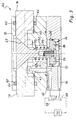
- FIGS. 3 and 4 show a second embodiment of the invention Invention in the form of a gripping device 60.
- the Gripping device 60 is largely with the gripping device 10 identical according to Figure 1 and 2.
- the identical components the gripping devices 10 and 60 are therefore with the provided with the same reference numbers.
- the gripping device 60 are different from the Gripping device 10 no valve-like sealing rings 44, but pass rings 62 between the base housing 12 and the Base jaws 16 and 18 provided. Between the pass rings 62, which are attached to the base body side, and the Surface of base jaws 16 and 18 is a smaller one Annular gap 64 is provided, which has a relatively high Forms flow resistance for the gas.
- the fitting rings 62 have a hard-wearing coating.
- the directional valve 66 opens or blocks the Exhaust duct 46 or connected to the exhaust duct 46, not shown line.
- the directional control valve 68 is for Circuit of the pressure channel 34 and the pressure chamber 32nd intended.
- the two way valves 66 and 68 are of a control unit 70 shown schematically connected.
- the exhaust passage 46 is locked, as the shown position of the directional valve 66 are removed can.
- About the exhaust passage 46 can therefore no gas in the Flow gripping device. Rather, it flows in outgoing Base jaws 16 and 18 due to the enlarging Cavity 42 gas from the clean room via the gap 64 in the Gripping device 60 a. Consequently, it is ensured that with extending base jaws 16 and 18 no Particle emission from the gripping device 60 can go out.
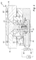
- FIG. 4 shows the entry situation of the base jaws 16 and FIG. 18.
- the control unit 70 To initiate the retraction movement the control unit 70 simultaneously switches the directional valves 66 and 68 in their respective second switching position.
- switching position of the directional control valve 68 flows from a pressure accumulator, not shown gas over the Pressure line 34 into the pressure chamber 32.
- the piston moves Therefore, in the direction indicated by the arrows 54 Direction.
- the volume of gas available decreases standing cavity 42 in the main body 12.
- fitting rings 62 which advantageously the Base jaws 16 and 18 do not touch, has the advantage that no abrasion or no wear, which leads to a Can cause pollution.
- the gripping device 60 has Overall, the advantage that due to the active circuit the directional control valves 66 and 68 via the control unit 70, in particular when returning the base jaws 16 and 18 within the gripping device 60 no overpressure arise has to be coupled to the exhaust duct 46 Open check valve, as in the gripping device 10 is provided.
- the directional control valve 66 is rather in suitable time automatically opened.
- the vacuum generator is advantageously also operated by the controller 70, and then when the cavity 42 due to the displacement of the base jaws 16 and 18 downsized.
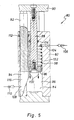
- FIG. 5 shows a third embodiment of the invention in the form of a linear drive 80.
- the linear drive 80 is intended for use in a clean room, which is why he must not run out of particulate emissions.
- the linear drive 80 has a main body 82 in which one in a cylinder 84 movable piston 86 is on.
- the piston 86 has a piston rod 88, the free end of the Main body 82 protrudes and connected to a lifting table 90 is.
- On the lifting table 90 is a guide rod 92nd arranged in a guide hole 94 of the main body 82nd intervenes.
- the compression spring 98 receiving cylinder space 102 - forms a cavity in the sense of claim 1 - is about an exhaust pipe 104 with a, not shown, off connected to the clean room leading line. This line is closed by a check valve 106.
- the guide hole 94 is formed as a blind hole. It is connected to an exhaust passage 108 which does not have a shown lead out of the clean room. These Line is provided with a check valve 110.
- the available for a gas volume cavity 116th within the guide hole 94 changes depending on the position of Guide rod 92 - which forms a second movement member - his volume.
- the cavity 116 is therefore also a Cavity in the sense of claim 1.
- valve-like sealing means 112 and 114 instead of valve-like sealing means 112 and 114, the flow resistance increasing column according to to provide the figures 3 and 4.
Landscapes
- Engineering & Computer Science (AREA)
- Robotics (AREA)
- Mechanical Engineering (AREA)
- Container, Conveyance, Adherence, Positioning, Of Wafer (AREA)
- Organic Low-Molecular-Weight Compounds And Preparation Thereof (AREA)
- Ventilation (AREA)
Abstract
Description
- Figur 1
- einen Längsschnitt durch eine erste erfindungsgemäße Greifvorrichtung beim Ausfahren der Grundbacken;
- Figur 2
- die Greifvorrichtung gemäß Figur 1 beim Einfahren der Grundbacken;
- Figur 3
- eine zweite erfindungsgemäße Greifvorrichtung beim Ausfahren der Grundbacken;
- Figur 4
- die Greifvorrichtung nach Figur 3 beim Einfahren der Grundbacken; und
- Figur 5
- einen erfindungsgemäßen Linearantrieb beim Einfahren des Bewegungsgliedes.
Claims (16)
- Handhabungsgerät (10, 60, 80), insbesondere zur Verwendung in Reinräumen, mit einem Grundkörper (12, 82), mit einer im Grundkörper (12, 82) vorhandenen Aussparung (20, 84, 94) zur Aufnahme wenigstens eines im Grundkörper (12, 82) verschieblich gelagerten Bewegungsglied (16, 18, 88, 92) und mit einem in dem Grundkörper (12, 82) angeordneten Antrieb (24, 26, 28, 84, 86), wobei das Bewegungsglied (16, 18, 88, 92) durch den Antrieb (24, 26, 28, 84, 86) wenigstens abschnittsweise aus dem Grundköper (12, 82) herausführbar ist und wobei aufgrund der Verschiebung des Bewegungsgliedes (16, 18, 88, 92) der in dem Grundkörper (12, 82) für ein Gasvolumen zur Verfügung stehende Hohlraum (42, 102, 116) sein Volumen ändert, dadurch gekennzeichnet, dass zwischen dem Grundkörper (12, 82) und der Oberfläche des aus dem Grundkörper (12, 82) herausführbaren Abschnitts des Bewegungsgliedes (16, 18, 88, 92) Dichtmittel (44, 64, 112, 114) vorgesehen sind, die infolge einer Verschiebung des Bewegungsgliedes (16, 18, 88, 92) bei Vergrößerung des Hohlraumes (42, 102, 116) Gas aus dem Reinraum in den Hohlraum (42, 102, 116) und bei Verkleinerung des Hohlraumes (42, 102, 116) kein Gas aus dem Hohlraum (42, 12, 116) in den Reinraum eindringen lassen und dass der Hohlraum (42, 102, 116) über einen Abgaskanal (46, 104, 108) mit der Außenseite des Grundköpers verbunden ist, wobei der Abgaskanal (46, 104, 108) einer aus dem Reinraum führenden Leitung verbunden werden kann und wobei Sperrmittel (48, 66, 106, 110) zur Regulierung des Strömungswiderstands in dem Abgaskanal (46, 104, 108) und/oder der Leitung vorgesehen sind, die infolge einer Verschiebung des Bewegungsgliedes (16, 18, 88, 92) bei Vergrößerung des Hohlraumes (42, 102, 116) kein Gas in den Hohlraum (42, 102, 116) einströmem lassen und bei Verkleinerung des Hphlraumes (42, 102, 116) Gas über den Abgaskanal (46, 104, 108) bzw. über die Leitung aus dem Hohlraum (42, 102, 116) ausströmen lassen.
- Handhabungsgerät (10, 80) nach Anspruch 1, dadurch gekennzeichnet, dass die Dichtmittel eine am Grundkörper angeordnete, sperrventilartig schaltende Dichtung (44, 112, 114) umfassen.
- Handhabungsgerät (60) nach Anspruch 1, dadurch gekennzeichnet, dass die Dichtmittel (62) einen kleinen Spalt (64) zwischen dem Grundkörper (12) und der Oberfläche des aus dem Grundkörper herausführbaren Abschnitts des Bewegungsgliedes (16, 18) umfassen, wobei der Spalt (64) einen relativ hohen Strömungswiderstand für das Gas bildet.
- Handhabungsgerät (10, 60, 80) nach Anspruch 1, 2 oder 3, dadurch gekennzeichnet, dass die Sperrmittel ein Sperrventil (48, 66, 106, 110), insbesondere ein Rückschlagventil (48, 106, 110), umfassen.
- Handhabungsgerät (60) nach einem der vorhergehenden Ansprüche, dadurch gekennzeichnet, dass die Sperrmittel (66) über Schaltmittel (70) in Abhängigkeit der Bewegung des Bewegungsgliedes (16, 18) und/oder des Antriebes (24) geschaltet werden.
- Handhabungsgerät (10, 60) nach einem der vorhergehenden Ansprüche, dadurch gekennzeichnet, dass der Antrieb (24) über ein in einem Getriebehohlraum (50) angeordneten Getriebe (22) mit dem Bewegungsglied (16, 18) gekoppelt ist.
- Handhabungsgerät (10, 60) nach Anspruch 6, dadurch gekennzeichnet, dass ein Verbindungskanal (52, 46) zwischen dem Hohlraum (42) und dem Getriebehohlraum (50) und/oder zwischen dem Abgaskanal (46) und Getriebehohlraum (50) vorgesehen ist.
- Handhabungsgerät (10, 60) nach Anspruch 6 oder 7, dadurch gekennzeichnet, dass das Getriebe ein Schrägzug- bzw. ein Keilhakengetriebe (22) ist.
- Handhabungsgerät (10, 60, 80) nach einem der vorhergehenden Ansprüche, dadurch gekennzeichnet, dass der Antrieb einen einseitig gasbeaufschlagbaren, in einem Zylinderraum (26, 102) axial verschiebbaren, über eine Kolbestange (30, 88) mit dem Bewegungsglied (16, 18, 88) gekoppelten Kolben 28, 86) umfasst, wobei sich aufgrund der Gasbeaufschlagung der Hohlraum (42, 102) verkleinert.
- Handhabungsgerät (10, 60, 80) nach Anspruch 9, dadurch gekennzeichnet, dass die nicht gasbeaufschlagbare Seite des Kolbens (28, 86) über ein Federelement (36, 98) druckbeaufschlagbar ist.
- Handhabungsgerät (10, 60, 80) nach einem der vorhergehenden Ansprüche, dadurch gekennzeichnet, dass der Abgaskanal (46, 104, 108) mit einem Unterdruckerzeuger gekoppelt ist.
- Handhabungsgerät (10, 60, 80) nach Anspruch 11, dadurch gekennzeichnet, dass der Unterdrückerzeuger den Hohlraum (42, 102, 116) mit Unterdruck beaufschlagt, wenn sich der Hohlraum (42, 102, 116) aufgrund der Verschiebung des Bewegungsgliedes (16, 18, 88, 92) verkleinert.
- Handhabungsgerät (10, 60) nach einem der vorhergehenden Ansprüche, dadurch gekennzeichnet, dass das Handhabungsgerät eine Greif- oder Spannvorrichtung, insbesondere ein Zwei-Finger-Parallelgreifer oder ein Drei- oder Mehr-Finger-Zentrischgreifer ist, wobei Grundbacken (16, 18) der Greif- oder Spannvorrichtung das Bewegungsglied bilden.
- Handhabungsgerät (80) nach einem der Ansprüche 1 bis 12, dadurch gekennzeichnet, dass das Handhabungsgerät ein Linearantrieb ist, wobei Kolbenstangen (88) und/oder Führungsstangen (92) des Linearantriebs das Bewegungsglied bilden.
- Verfahren zum Berteiben eines Handhabungsgeräts (10, 60, 80) nach einem der vorhergehenden Ansprüche, dadurch gekennzeichnet, dass ein Steuergerät (70) die Sperrmittel (66) abhängig von der Bewegung des Bewegungsgliedes (16, 18, 88, 92) und/oder des Antriebs (24) derart schaltet, dass die Sperrmittel (66) geöffnet sind wenn sich der Hohlraum (42, 102, 116) aufgrund der Verschiebung des Bewegungsgliedes (16, 18, 88, 92) verkleinert und geschlossen sind, wenn sich der Hohlraum (42, 102, 116) vergrößert.
- Verfahren nach Anspruch 15, dadurch gekennzeichnet, dass der Unterdruckerzeuger über das Steuergerät (70) betätigt wird und den Hohlraum (42, 102, 116) dann mit Unterdruck beaufschlagt, wenn sich der Hohlraum (42, 102, 116) aufgrund der Verschiebung des Bewegungsgliedes (16, 18, 88, 92) verkleinert.
Applications Claiming Priority (2)
| Application Number | Priority Date | Filing Date | Title |
|---|---|---|---|
| DE10146196 | 2001-09-14 | ||
| DE10146196A DE10146196C1 (de) | 2001-09-14 | 2001-09-14 | Handhabungsgerät, insbesondere zur Verwendung in Reinräumen |
Publications (2)
| Publication Number | Publication Date |
|---|---|
| EP1293309A1 true EP1293309A1 (de) | 2003-03-19 |
| EP1293309B1 EP1293309B1 (de) | 2004-06-30 |
Family
ID=7699562
Family Applications (1)
| Application Number | Title | Priority Date | Filing Date |
|---|---|---|---|
| EP02020510A Expired - Lifetime EP1293309B1 (de) | 2001-09-14 | 2002-09-13 | Handhabungsgerät, insbesondere zur Verwendung in Reinräumen |
Country Status (3)
| Country | Link |
|---|---|
| EP (1) | EP1293309B1 (de) |
| AT (1) | ATE270171T1 (de) |
| DE (2) | DE10146196C1 (de) |
Cited By (1)
| Publication number | Priority date | Publication date | Assignee | Title |
|---|---|---|---|---|
| JPWO2021044944A1 (de) * | 2019-09-03 | 2021-03-11 |
Families Citing this family (6)
| Publication number | Priority date | Publication date | Assignee | Title |
|---|---|---|---|---|
| DE10350801A1 (de) | 2003-10-29 | 2005-06-16 | Kuka Roboter Gmbh | Handhabungsgerät, insbesondere für die Nahrungsmittel-Industrie |
| DE102009008966B4 (de) * | 2009-02-13 | 2011-02-17 | Asys Automatic Systems Gmbh & Co. Kg | Drehverbindung zwischen Bauteilen in Reinraumbearbeitungsanlagen |
| DE102010006319A1 (de) * | 2010-01-29 | 2011-08-04 | Krones Ag, 93073 | Vorrichtung zum Behandeln von Behältnissen |
| DE102013019035B4 (de) * | 2013-11-15 | 2019-05-09 | Günther Zimmer | Greifvorrichtung mit Führungsnutdichtung |
| DE102017109291B4 (de) | 2016-04-28 | 2019-12-24 | Karsten Weiß | Greifmodul |
| US12595811B2 (en) | 2024-04-30 | 2026-04-07 | Rosenboom Machine & Tool, Inc. | Seal plate method for communicating retract oil to retract side of piston in hydraulic cylinder |
Citations (4)
| Publication number | Priority date | Publication date | Assignee | Title |
|---|---|---|---|---|
| US4913481A (en) * | 1988-09-13 | 1990-04-03 | Applied Power Inc. | Clean room gripper |
| EP0438030A1 (de) * | 1990-01-17 | 1991-07-24 | GebràDer Sulzer Aktiengesellschaft | Greifergehäuse für im Reinraum eingesetzten Roboter |
| DE19604649A1 (de) * | 1996-02-09 | 1997-08-14 | Schunk Fritz Gmbh | Greifvorrichtung bzw. Spannvorrichtung |
| US5839770A (en) * | 1997-06-26 | 1998-11-24 | Zaytran, Inc. | Robotic gripper |
-
2001
- 2001-09-14 DE DE10146196A patent/DE10146196C1/de not_active Expired - Fee Related
-
2002
- 2002-09-13 EP EP02020510A patent/EP1293309B1/de not_active Expired - Lifetime
- 2002-09-13 DE DE50200569T patent/DE50200569D1/de not_active Expired - Lifetime
- 2002-09-13 AT AT02020510T patent/ATE270171T1/de not_active IP Right Cessation
Patent Citations (4)
| Publication number | Priority date | Publication date | Assignee | Title |
|---|---|---|---|---|
| US4913481A (en) * | 1988-09-13 | 1990-04-03 | Applied Power Inc. | Clean room gripper |
| EP0438030A1 (de) * | 1990-01-17 | 1991-07-24 | GebràDer Sulzer Aktiengesellschaft | Greifergehäuse für im Reinraum eingesetzten Roboter |
| DE19604649A1 (de) * | 1996-02-09 | 1997-08-14 | Schunk Fritz Gmbh | Greifvorrichtung bzw. Spannvorrichtung |
| US5839770A (en) * | 1997-06-26 | 1998-11-24 | Zaytran, Inc. | Robotic gripper |
Cited By (5)
| Publication number | Priority date | Publication date | Assignee | Title |
|---|---|---|---|---|
| JPWO2021044944A1 (de) * | 2019-09-03 | 2021-03-11 | ||
| WO2021044944A1 (ja) * | 2019-09-03 | 2021-03-11 | 株式会社北川鉄工所 | 密封型グリッパ |
| CN114340853A (zh) * | 2019-09-03 | 2022-04-12 | 株式会社北川铁工所 | 密封型抓取器 |
| CN114340853B (zh) * | 2019-09-03 | 2024-09-13 | 株式会社北川铁工所 | 密封型抓取器 |
| TWI862673B (zh) * | 2019-09-03 | 2024-11-21 | 日商北川鐵工所股份有限公司 | 密封型抓取器 |
Also Published As
| Publication number | Publication date |
|---|---|
| DE50200569D1 (de) | 2004-08-05 |
| ATE270171T1 (de) | 2004-07-15 |
| DE10146196C1 (de) | 2002-11-28 |
| EP1293309B1 (de) | 2004-06-30 |
Similar Documents
| Publication | Publication Date | Title |
|---|---|---|
| DE4114940C2 (de) | Pressenanordnung | |
| DE3934124A1 (de) | Druckluftgetriebene pumpenanordnung | |
| DE102010021202A1 (de) | Lasthalteventil mit Druckbegrenzungsfunktion | |
| EP1293309B1 (de) | Handhabungsgerät, insbesondere zur Verwendung in Reinräumen | |
| DE102011100632A1 (de) | Kolben-Zylinder-Einheit | |
| DE102016215311A1 (de) | Hydraulischer Antrieb | |
| EP1428962B1 (de) | Kolben-Zylinder-Einheit | |
| DE10026616B4 (de) | Druckübersetzer, insbesondere hydropneumatischer Druckübersetzer | |
| DE20106764U1 (de) | Bergbauzylinder mit Beschichtung | |
| DE9402400U1 (de) | Türfeststeller für Türen | |
| DE2900015A1 (de) | Gleichgang-teleskop-zylinder | |
| DE102009018768B4 (de) | Druckmittelbetätigbarer Aktuator mit integrierter Schnellentlüftung und zusätzlichem Schaltkraftimpuls beim Entlüften | |
| DE10356598B3 (de) | Verriegelungszylinder | |
| EP0442842B1 (de) | Hydraulikzylinder mit Druckübersetzung | |
| EP0581270B1 (de) | Teleskopanordnung aus mehreren Tauchkolbenzylindern, insbesondere für Teleskopausleger bei Kranen oder dergleichen | |
| DE10356596B3 (de) | Verriegelungszylinder | |
| DE3221984A1 (de) | Hydraulikzylinder | |
| DE10108257B4 (de) | Hydraulikzylinder | |
| EP3746662B1 (de) | Steuerventilanordnung zur indirekten pneumatischen steuerung und verfahren zum steuern eines arbeitsfluiddrucks | |
| DE2641216C2 (de) | Mehrstufiger hydraulischer Teleskopzylinder | |
| DE102004047449C5 (de) | Blockierbare Kolben-Zylindereinheit | |
| DE10356597B3 (de) | Verriegelungszylinder | |
| EP0742373B1 (de) | Pneumatische Antriebsvorrichtung | |
| DE102020205547A1 (de) | Logikventil zur steuerung eines hydraulischen aktors und entsprechender hydraulikkreis | |
| DE102014222326A1 (de) | Hydraulikanordnung |
Legal Events
| Date | Code | Title | Description |
|---|---|---|---|
| PUAI | Public reference made under article 153(3) epc to a published international application that has entered the european phase |
Free format text: ORIGINAL CODE: 0009012 |
|
| AK | Designated contracting states |
Kind code of ref document: A1 Designated state(s): AT BE BG CH CY CZ DE DK EE ES FI FR GB GR IE IT LI LU MC NL PT SE SK TR Designated state(s): AT BE BG CH CY CZ DE DK EE ES FI FR GB GR IE IT LI LU MC NL PT SE SK TR |
|
| AX | Request for extension of the european patent |
Extension state: AL LT LV MK RO SI |
|
| 17P | Request for examination filed |
Effective date: 20030515 |
|
| AKX | Designation fees paid |
Designated state(s): AT BE BG CH CY CZ DE DK EE ES FI FR GB GR IE IT LI LU MC NL PT SE SK TR |
|
| GRAP | Despatch of communication of intention to grant a patent |
Free format text: ORIGINAL CODE: EPIDOSNIGR1 |
|
| GRAA | (expected) grant |
Free format text: ORIGINAL CODE: 0009210 |
|
| GRAS | Grant fee paid |
Free format text: ORIGINAL CODE: EPIDOSNIGR3 |
|
| RIN1 | Information on inventor provided before grant (corrected) |
Inventor name: SCHUSTER, ANDREAS Inventor name: HOCH, ANDREAS |
|
| AK | Designated contracting states |
Kind code of ref document: B1 Designated state(s): AT BE BG CH CY CZ DE DK EE ES FI FR GB GR IE IT LI LU MC NL PT SE SK TR |
|
| PG25 | Lapsed in a contracting state [announced via postgrant information from national office to epo] |
Ref country code: NL Free format text: LAPSE BECAUSE OF FAILURE TO SUBMIT A TRANSLATION OF THE DESCRIPTION OR TO PAY THE FEE WITHIN THE PRESCRIBED TIME-LIMIT Effective date: 20040630 Ref country code: CZ Free format text: LAPSE BECAUSE OF FAILURE TO SUBMIT A TRANSLATION OF THE DESCRIPTION OR TO PAY THE FEE WITHIN THE PRESCRIBED TIME-LIMIT Effective date: 20040630 Ref country code: BG Free format text: LAPSE BECAUSE OF FAILURE TO SUBMIT A TRANSLATION OF THE DESCRIPTION OR TO PAY THE FEE WITHIN THE PRESCRIBED TIME-LIMIT Effective date: 20040630 Ref country code: GB Free format text: LAPSE BECAUSE OF FAILURE TO SUBMIT A TRANSLATION OF THE DESCRIPTION OR TO PAY THE FEE WITHIN THE PRESCRIBED TIME-LIMIT Effective date: 20040630 Ref country code: IE Free format text: LAPSE BECAUSE OF FAILURE TO SUBMIT A TRANSLATION OF THE DESCRIPTION OR TO PAY THE FEE WITHIN THE PRESCRIBED TIME-LIMIT Effective date: 20040630 Ref country code: SK Free format text: LAPSE BECAUSE OF FAILURE TO SUBMIT A TRANSLATION OF THE DESCRIPTION OR TO PAY THE FEE WITHIN THE PRESCRIBED TIME-LIMIT Effective date: 20040630 Ref country code: TR Free format text: LAPSE BECAUSE OF FAILURE TO SUBMIT A TRANSLATION OF THE DESCRIPTION OR TO PAY THE FEE WITHIN THE PRESCRIBED TIME-LIMIT Effective date: 20040630 Ref country code: EE Free format text: LAPSE BECAUSE OF FAILURE TO SUBMIT A TRANSLATION OF THE DESCRIPTION OR TO PAY THE FEE WITHIN THE PRESCRIBED TIME-LIMIT Effective date: 20040630 Ref country code: CY Free format text: LAPSE BECAUSE OF FAILURE TO SUBMIT A TRANSLATION OF THE DESCRIPTION OR TO PAY THE FEE WITHIN THE PRESCRIBED TIME-LIMIT Effective date: 20040630 Ref country code: FI Free format text: LAPSE BECAUSE OF FAILURE TO SUBMIT A TRANSLATION OF THE DESCRIPTION OR TO PAY THE FEE WITHIN THE PRESCRIBED TIME-LIMIT Effective date: 20040630 |
|
| REG | Reference to a national code |
Ref country code: CH Ref legal event code: NV Representative=s name: MICHELI & CIE INGENIEURS-CONSEILS Ref country code: CH Ref legal event code: EP Ref country code: GB Ref legal event code: FG4D Free format text: NOT ENGLISH |
|
| REG | Reference to a national code |
Ref country code: IE Ref legal event code: FG4D Free format text: GERMAN |
|
| REF | Corresponds to: |
Ref document number: 50200569 Country of ref document: DE Date of ref document: 20040805 Kind code of ref document: P |
|
| PG25 | Lapsed in a contracting state [announced via postgrant information from national office to epo] |
Ref country code: LU Free format text: LAPSE BECAUSE OF NON-PAYMENT OF DUE FEES Effective date: 20040913 |
|
| PG25 | Lapsed in a contracting state [announced via postgrant information from national office to epo] |
Ref country code: MC Free format text: LAPSE BECAUSE OF NON-PAYMENT OF DUE FEES Effective date: 20040930 Ref country code: GR Free format text: LAPSE BECAUSE OF FAILURE TO SUBMIT A TRANSLATION OF THE DESCRIPTION OR TO PAY THE FEE WITHIN THE PRESCRIBED TIME-LIMIT Effective date: 20040930 Ref country code: DK Free format text: LAPSE BECAUSE OF FAILURE TO SUBMIT A TRANSLATION OF THE DESCRIPTION OR TO PAY THE FEE WITHIN THE PRESCRIBED TIME-LIMIT Effective date: 20040930 Ref country code: BE Free format text: LAPSE BECAUSE OF NON-PAYMENT OF DUE FEES Effective date: 20040930 Ref country code: SE Free format text: LAPSE BECAUSE OF FAILURE TO SUBMIT A TRANSLATION OF THE DESCRIPTION OR TO PAY THE FEE WITHIN THE PRESCRIBED TIME-LIMIT Effective date: 20040930 |
|
| PG25 | Lapsed in a contracting state [announced via postgrant information from national office to epo] |
Ref country code: ES Free format text: LAPSE BECAUSE OF FAILURE TO SUBMIT A TRANSLATION OF THE DESCRIPTION OR TO PAY THE FEE WITHIN THE PRESCRIBED TIME-LIMIT Effective date: 20041011 |
|
| GBV | Gb: ep patent (uk) treated as always having been void in accordance with gb section 77(7)/1977 [no translation filed] |
Effective date: 20040630 |
|
| NLV1 | Nl: lapsed or annulled due to failure to fulfill the requirements of art. 29p and 29m of the patents act | ||
| ET | Fr: translation filed | ||
| REG | Reference to a national code |
Ref country code: IE Ref legal event code: FD4D |
|
| BERE | Be: lapsed |
Owner name: SCHUNK G.M.B.H. & CO. KG FABRIK FUR SPANN- UND GRE Effective date: 20040930 |
|
| PLBE | No opposition filed within time limit |
Free format text: ORIGINAL CODE: 0009261 |
|
| STAA | Information on the status of an ep patent application or granted ep patent |
Free format text: STATUS: NO OPPOSITION FILED WITHIN TIME LIMIT |
|
| 26N | No opposition filed |
Effective date: 20050331 |
|
| BERE | Be: lapsed |
Owner name: *SCHUNK G.M.B.H. & CO. K.G. FABRIK FUR SPANN- UND Effective date: 20040930 |
|
| PG25 | Lapsed in a contracting state [announced via postgrant information from national office to epo] |
Ref country code: PT Free format text: LAPSE BECAUSE OF NON-PAYMENT OF DUE FEES Effective date: 20041130 |
|
| PGFP | Annual fee paid to national office [announced via postgrant information from national office to epo] |
Ref country code: AT Payment date: 20080919 Year of fee payment: 7 |
|
| PG25 | Lapsed in a contracting state [announced via postgrant information from national office to epo] |
Ref country code: AT Free format text: LAPSE BECAUSE OF NON-PAYMENT OF DUE FEES Effective date: 20090913 |
|
| REG | Reference to a national code |
Ref country code: FR Ref legal event code: PLFP Year of fee payment: 15 |
|
| REG | Reference to a national code |
Ref country code: FR Ref legal event code: PLFP Year of fee payment: 16 |
|
| REG | Reference to a national code |
Ref country code: FR Ref legal event code: PLFP Year of fee payment: 17 |
|
| PGFP | Annual fee paid to national office [announced via postgrant information from national office to epo] |
Ref country code: CH Payment date: 20210920 Year of fee payment: 20 Ref country code: FR Payment date: 20210921 Year of fee payment: 20 Ref country code: IT Payment date: 20210922 Year of fee payment: 20 |
|
| PGFP | Annual fee paid to national office [announced via postgrant information from national office to epo] |
Ref country code: DE Payment date: 20210920 Year of fee payment: 20 |
|
| REG | Reference to a national code |
Ref country code: DE Ref legal event code: R071 Ref document number: 50200569 Country of ref document: DE |
|
| REG | Reference to a national code |
Ref country code: CH Ref legal event code: PL |