EP1293467A2 - Grappin pour transporter des bobines de barre - Google Patents
Grappin pour transporter des bobines de barre Download PDFInfo
- Publication number
- EP1293467A2 EP1293467A2 EP02020476A EP02020476A EP1293467A2 EP 1293467 A2 EP1293467 A2 EP 1293467A2 EP 02020476 A EP02020476 A EP 02020476A EP 02020476 A EP02020476 A EP 02020476A EP 1293467 A2 EP1293467 A2 EP 1293467A2
- Authority
- EP
- European Patent Office
- Prior art keywords
- rod
- coil
- grab
- grab according
- pivoted
- Prior art date
- Legal status (The legal status is an assumption and is not a legal conclusion. Google has not performed a legal analysis and makes no representation as to the accuracy of the status listed.)
- Withdrawn
Links
Images



Classifications
-
- B—PERFORMING OPERATIONS; TRANSPORTING
- B66—HOISTING; LIFTING; HAULING
- B66C—CRANES; LOAD-ENGAGING ELEMENTS OR DEVICES FOR CRANES, CAPSTANS, WINCHES, OR TACKLES
- B66C1/00—Load-engaging elements or devices attached to lifting or lowering gear of cranes or adapted for connection therewith for transmitting lifting forces to articles or groups of articles
- B66C1/10—Load-engaging elements or devices attached to lifting or lowering gear of cranes or adapted for connection therewith for transmitting lifting forces to articles or groups of articles by mechanical means
- B66C1/42—Gripping members engaging only the external or internal surfaces of the articles
- B66C1/422—Gripping members engaging only the external or internal surfaces of the articles actuated by lifting force
-
- B—PERFORMING OPERATIONS; TRANSPORTING
- B21—MECHANICAL METAL-WORKING WITHOUT ESSENTIALLY REMOVING MATERIAL; PUNCHING METAL
- B21C—MANUFACTURE OF METAL SHEETS, WIRE, RODS, TUBES, PROFILES OR LIKE SEMI-MANUFACTURED PRODUCTS OTHERWISE THAN BY ROLLING; AUXILIARY OPERATIONS USED IN CONNECTION WITH METAL-WORKING WITHOUT ESSENTIALLY REMOVING MATERIAL
- B21C47/00—Winding-up, coiling or winding-off metal wire, metal band or other flexible metal material characterised by features relevant to metal processing only
- B21C47/24—Transferring coils to or from winding apparatus or to or from operative position therein; Preventing uncoiling during transfer
-
- B—PERFORMING OPERATIONS; TRANSPORTING
- B66—HOISTING; LIFTING; HAULING
- B66C—CRANES; LOAD-ENGAGING ELEMENTS OR DEVICES FOR CRANES, CAPSTANS, WINCHES, OR TACKLES
- B66C1/00—Load-engaging elements or devices attached to lifting or lowering gear of cranes or adapted for connection therewith for transmitting lifting forces to articles or groups of articles
- B66C1/04—Load-engaging elements or devices attached to lifting or lowering gear of cranes or adapted for connection therewith for transmitting lifting forces to articles or groups of articles by magnetic means
-
- B—PERFORMING OPERATIONS; TRANSPORTING
- B66—HOISTING; LIFTING; HAULING
- B66C—CRANES; LOAD-ENGAGING ELEMENTS OR DEVICES FOR CRANES, CAPSTANS, WINCHES, OR TACKLES
- B66C1/00—Load-engaging elements or devices attached to lifting or lowering gear of cranes or adapted for connection therewith for transmitting lifting forces to articles or groups of articles
- B66C1/10—Load-engaging elements or devices attached to lifting or lowering gear of cranes or adapted for connection therewith for transmitting lifting forces to articles or groups of articles by mechanical means
- B66C1/42—Gripping members engaging only the external or internal surfaces of the articles
- B66C1/44—Gripping members engaging only the external or internal surfaces of the articles and applying frictional forces
- B66C1/48—Gripping members engaging only the external or internal surfaces of the articles and applying frictional forces to vertical edge portions of sheets, tubes, or like thin or thin-walled articles
- B66C1/485—Coil lifting devices
-
- B—PERFORMING OPERATIONS; TRANSPORTING
- B66—HOISTING; LIFTING; HAULING
- B66C—CRANES; LOAD-ENGAGING ELEMENTS OR DEVICES FOR CRANES, CAPSTANS, WINCHES, OR TACKLES
- B66C1/00—Load-engaging elements or devices attached to lifting or lowering gear of cranes or adapted for connection therewith for transmitting lifting forces to articles or groups of articles
- B66C1/10—Load-engaging elements or devices attached to lifting or lowering gear of cranes or adapted for connection therewith for transmitting lifting forces to articles or groups of articles by mechanical means
- B66C1/42—Gripping members engaging only the external or internal surfaces of the articles
- B66C1/44—Gripping members engaging only the external or internal surfaces of the articles and applying frictional forces
- B66C1/54—Internally-expanding grippers for handling hollow articles
Definitions
- the present invention relates to a grab for conveying coils of rod, particularly for conveying rod for reinforced concrete.
- grabs or magnets are currently used to convey coils of rod and can be provided so as to grip the coil either on the outside or on the inside.
- the coils gripped by the grabs or magnets must then be fitted on the reels, and to perform this operation it is necessary to use first the grab or magnet to lift the coil, then harness the coil with chains, lift it and then fit it over the reel.
- the aim of the present invention is to provide a grab for conveying coils that allows to fit the coils directly on the reels once they have been lifted by the grab.
- an object of the present invention is to provide a grab for conveying coils that can be used both to lift the coils from the outside and to lift the coils from the inside of the coil itself, without any constructive variation.
- Another object of the present invention is to provide a grab for conveying coils that can be used with coils of different diameters.
- Another object of the present invention is to provide a grab for conveying coils that is highly reliable, relatively simple to manufacture, and at competitive costs.
- a grab for lifting coils of rod or the like characterized in that it comprises a supporting structure that is suitable to form an empty central region and engagement means that are pivoted to said supporting structure and are suitable to grip a coil of rod in order to lift it, said engagement means being actuated by tension elements that allow to clamp said engagement means on said coil and subsequently lift it.
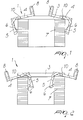
- the grab according to the present invention comprises a structure 2, which has for example a quadrilateral shape and is constituted by four rod-like elements 3 that are arranged with respect to each other so as to constitute a quadrilateral that is open at the center.
- Engagement means are articulated to the quadrilateral structure, and each engagement means is conveniently constituted by a right-angled jaw 4 that has, at a vertical portion 5, grip means 6, constituted for example by teeth that are suitable to engage the coil of rod to be lifted, which is generally designated by the reference numeral 7.
- the engagement means 4 constituted by a pair of rod-like elements arranged at right angles to each other, are provided with coupling means 8 that allow the engagement of lifting means in order to achieve a rotation of the engagement means 4 about a point 10 for the pivoting of the engagement means to the rod-like elements 3 that constitute the previously described quadrilateral structure.
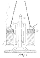
- the coupling means 8 allow the engagement of tension elements or chains 9, which allow, when conveniently subjected to traction, for example as shown by Figure 3 by means of a hook 11, to turn the engagement means 4 about their pivoting points 10, thus achieving the engagement of the teeth 6 against the outer surface of the coil 7 and therefore allowing to lift the entire coil.
- the grab shown in Figures 1 and 3 can also be used to engage the coil internally instead of externally, as shown in Figures 2 and 2a.
- the grab according to the invention is such as to leave the central region free, so that as shown in Figure 3 the coil 7 can be fitted easily over a reel 12 without said fitting being hindered by the structure of the grab.
- Figure 4 which is a top plan view of the grab, clearly shows that the quadrilateral structure formed by the rod-like elements 3 allows to leave the central region suitable to be arranged above the coil 7, free to be fitted on the reel 12, so that the grab can be used to lift the coil 7 and then fit it directly onto the reel 12.
- the jaws 4 are provided at the corners of the quadrilateral and therefore there are four jaws that engage the coil 7 in positions that are diametrically opposite in pairs.
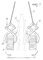
- each one of said engagement means is conveniently constituted by an articulated parallelogram-like structure 19 that ends with two curved elongated portions 20 and 21 that are suitable to form a sort of tongs for gripping the coil 7.
- one or more pairs of engagement means constituted as described above are provided.
- the tension elements or chains 9 are connected directly to the articulated parallelogram structure 19 at the upper vertex of the structure, in the opposite position with respect to the curved extension elements 20 and 21 that constitute the tongs.
- the central region at the central cavity of the coil 7 is kept free, so that the grab according to the invention can pick up the coil 7 and fit it directly onto the reel 12 without any interference.
- Figure 6 is a view of a fifth embodiment of the grab according to the present invention, wherein the engagement means are conveniently constituted by magnets 30 supported by a supporting structure 31 that is open centrally in order to allow the passage of the reel 12.
- the electric or permanent magnets can be operated electrically or manually to allow attraction between the magnet and the coil of rod.
- the grab is provided by way of the grip means described above, it is possible to provide screens 32 that are supported by the supporting structure and are arranged parallel to the vertical extension of the coils of rod and externally thereto, so as to prevent the grip means from striking or jamming between the turns of the coils.
- the grab according to the invention fully achieves the intended aim and objects, since it allows to lift and grip a coil 7 of rod and then directly place the coil on a reel 12, without having to harness the coil and remove the grab.
- the very low height of the grab according to the present invention allows to use it even when the available height is limited.
- the embodiment with a quadrilateral structure of the grab according to the present invention, as well as the structure with just two grip arms, is the most advantageous as regards ease of grab positioning.
- this embodiment in fact allows to insert the arms of the grab in the natural spaces that form, without having to space the coils in order to leave the space determined by the dimensions of said grab.
- Figure 7 illustrates the use, in the grab according to the present invention, of a retention gear that allows to prevent the jaws of the grab from disengaging or engaging when this is not intended.
- the retention device comprises a rod-like element 40, which is rigidly coupled to an upper ring 41, with which the coupling means 8 that allow the engagement of tension elements or chains are engaged.
- the rod-like element 40 is provided with a rack on which a gear 42 can mesh, said gear having a substantially L-shaped element 43 that abuts against a pivot 44 that is supported by an element 45 that protrudes at right angles to the rod-like element 40.
- the gear 42 and the element 43 are rigidly coupled to an arm 45, which is in turn rigidly coupled to a ring 46 that is arranged substantially opposite to the upper ring 41 and is meant to rest on the coils of rod.
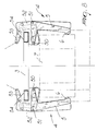
- Figure 8 illustrates a variation of the first embodiment, in which identical reference numerals designate identical elements.
- each jaw again designated by the reference numeral 4
- each jaw is constituted by a vertical portion 5 that has at least one tooth 6, and the vertical portion is shaped like a right-angled lever and is pivoted, at one end 50, to a fixed point of the grab and, at the pivot 51, to an arm 52, to which an additional rod-like element 53 is in turn pivoted, the tension element being connected to such additional rod-like element.
- traction on the tension element allows to grip the coil 7 by engagement of the tooth 6 with the coil, while the release of the tension element allows to turn the rod-like element 53 about the point where it is pivoted to a fixed point of the grab, thus allowing the consequent rotation, transmitted by the arm 52, of the right-angled lever constituted by the vertical portion 5.
- the rotation of the right-angled lever about the pivot 50 allows it to open and allows to release the coil 7.
- the grab according to the present invention can be provided with a suitable coupling for the prongs of a fork-lift truck that allows to use the grab even at sites that are not equipped with fixed lifting means.
- the materials used may be any according to requirements and to the state of the art.
Landscapes
- Engineering & Computer Science (AREA)
- Mechanical Engineering (AREA)
- Load-Engaging Elements For Cranes (AREA)
- Clamps And Clips (AREA)
- Forklifts And Lifting Vehicles (AREA)
Applications Claiming Priority (2)
| Application Number | Priority Date | Filing Date | Title |
|---|---|---|---|
| IT2001MI001932A ITMI20011932A1 (it) | 2001-09-14 | 2001-09-14 | Struttura di pinza per il trasporto di rotoli di tondino |
| ITMI20011932 | 2001-09-14 |
Publications (2)
| Publication Number | Publication Date |
|---|---|
| EP1293467A2 true EP1293467A2 (fr) | 2003-03-19 |
| EP1293467A3 EP1293467A3 (fr) | 2003-03-26 |
Family
ID=11448380
Family Applications (1)
| Application Number | Title | Priority Date | Filing Date |
|---|---|---|---|
| EP02020476A Withdrawn EP1293467A3 (fr) | 2001-09-14 | 2002-09-12 | Grappin pour transporter des bobines de barre |
Country Status (3)
| Country | Link |
|---|---|
| EP (1) | EP1293467A3 (fr) |
| ES (1) | ES2250019T1 (fr) |
| IT (1) | ITMI20011932A1 (fr) |
Cited By (5)
| Publication number | Priority date | Publication date | Assignee | Title |
|---|---|---|---|---|
| EP1473267A1 (fr) * | 2003-04-30 | 2004-11-03 | Potain | Dispositif de lestage pour grue |
| WO2008136664A1 (fr) * | 2007-05-08 | 2008-11-13 | Inter Product B.V. | Pince de levage |
| CN103879929A (zh) * | 2014-04-16 | 2014-06-25 | 国家电网公司 | 一种用于大口径电缆线圈运输的辅助装置及其使用方法 |
| CN107601259A (zh) * | 2017-08-29 | 2018-01-19 | 建科机械(天津)股份有限公司 | 一种吊运工具 |
| EP4015711A1 (fr) * | 2020-12-09 | 2022-06-22 | Kobelco Construction Machinery Co., Ltd. | Appareil de support et machine de travail le comprenant |
Citations (4)
| Publication number | Priority date | Publication date | Assignee | Title |
|---|---|---|---|---|
| US1487277A (en) | 1923-03-10 | 1924-03-18 | William A Shinner | Automatic grapple |
| US3155416A (en) | 1962-08-07 | 1964-11-03 | Cullen Friestedt Company | Automatic leveling device for tongs |
| FR1543659A (fr) | 1966-12-29 | 1968-10-25 | Tezuka Kosan Kk | Dispositif de pinces notamment pour la manipulation de blocs de déchets métalliques |
| DE9214264U1 (de) | 1992-10-22 | 1993-01-14 | Bauer, Heinz-Dieter, 4286 Südlohn | Faßhebevorrichtung |
Family Cites Families (4)
| Publication number | Priority date | Publication date | Assignee | Title |
|---|---|---|---|---|
| US2385049A (en) * | 1944-06-17 | 1945-09-18 | Raymond H Bates | Lifting tongs |
| US2576193A (en) * | 1949-06-20 | 1951-11-27 | Reynolds Kenneth Lee | Barrel grapple |
| FR1200429A (fr) * | 1958-06-21 | 1959-12-21 | Treuils Ponts Levage & Manuten | Pince pour la manutention de bobines de fils métalliques et d'objets analogues |
| US4641876A (en) * | 1985-07-29 | 1987-02-10 | Zurex Corporation | Coil edge protecting coil lifter and insert |
-
2001
- 2001-09-14 IT IT2001MI001932A patent/ITMI20011932A1/it unknown
-
2002
- 2002-09-12 EP EP02020476A patent/EP1293467A3/fr not_active Withdrawn
- 2002-09-12 ES ES02020476T patent/ES2250019T1/es active Pending
Patent Citations (4)
| Publication number | Priority date | Publication date | Assignee | Title |
|---|---|---|---|---|
| US1487277A (en) | 1923-03-10 | 1924-03-18 | William A Shinner | Automatic grapple |
| US3155416A (en) | 1962-08-07 | 1964-11-03 | Cullen Friestedt Company | Automatic leveling device for tongs |
| FR1543659A (fr) | 1966-12-29 | 1968-10-25 | Tezuka Kosan Kk | Dispositif de pinces notamment pour la manipulation de blocs de déchets métalliques |
| DE9214264U1 (de) | 1992-10-22 | 1993-01-14 | Bauer, Heinz-Dieter, 4286 Südlohn | Faßhebevorrichtung |
Cited By (10)
| Publication number | Priority date | Publication date | Assignee | Title |
|---|---|---|---|---|
| EP1473267A1 (fr) * | 2003-04-30 | 2004-11-03 | Potain | Dispositif de lestage pour grue |
| FR2854393A1 (fr) * | 2003-04-30 | 2004-11-05 | Potain Sa | Dispositif de lestage pour grue |
| US7093729B2 (en) | 2003-04-30 | 2006-08-22 | Potain | Ballasting device for a crane |
| WO2008136664A1 (fr) * | 2007-05-08 | 2008-11-13 | Inter Product B.V. | Pince de levage |
| US8226139B2 (en) | 2007-05-08 | 2012-07-24 | The Crosby Group LLC | Lifting clamp |
| CN103879929A (zh) * | 2014-04-16 | 2014-06-25 | 国家电网公司 | 一种用于大口径电缆线圈运输的辅助装置及其使用方法 |
| CN103879929B (zh) * | 2014-04-16 | 2016-03-16 | 江苏省电力公司扬州市江都供电公司 | 一种用于大口径电缆线圈运输的辅助装置及其使用方法 |
| CN107601259A (zh) * | 2017-08-29 | 2018-01-19 | 建科机械(天津)股份有限公司 | 一种吊运工具 |
| CN107601259B (zh) * | 2017-08-29 | 2020-02-11 | 建科机械(天津)股份有限公司 | 一种吊运工具 |
| EP4015711A1 (fr) * | 2020-12-09 | 2022-06-22 | Kobelco Construction Machinery Co., Ltd. | Appareil de support et machine de travail le comprenant |
Also Published As
| Publication number | Publication date |
|---|---|
| ITMI20011932A1 (it) | 2003-03-14 |
| ES2250019T1 (es) | 2006-04-16 |
| EP1293467A3 (fr) | 2003-03-26 |
| ITMI20011932A0 (it) | 2001-09-14 |
Similar Documents
| Publication | Publication Date | Title |
|---|---|---|
| US2850189A (en) | Grapple | |
| EP1293467A2 (fr) | Grappin pour transporter des bobines de barre | |
| US2680644A (en) | Apparatus for handling coiled material | |
| JP4030022B1 (ja) | 吊り治具 | |
| JP4002257B2 (ja) | 受動体係合式ベルクランク吊り具 | |
| EP1033342A3 (fr) | Pince de levage pour transporter des bobines de bande métallique | |
| US2519067A (en) | Barrel lifter | |
| US3131961A (en) | Hoisting devices | |
| US5513944A (en) | Roll handling apparatus for fork lift trucks | |
| JP2011240998A (ja) | 吊り具及びこれを用いた吊り荷の吊り上げ搬送方法 | |
| KR102502007B1 (ko) | 판넬소재 흡착 이송이 가능한 호이스트용 행거 | |
| CN115611139B (zh) | 一种公路铺设施工用起重设备 | |
| JP2842780B2 (ja) | 円筒形重量物の吊具 | |
| KR101567987B1 (ko) | 안전 후크 | |
| JPS6045113B2 (ja) | 充填された袋を持ち上げる吊り具 | |
| JP3523916B2 (ja) | コイル状圧延重量物の起伏装置 | |
| CN220976403U (zh) | 一种台车拼装吊具 | |
| CN219469430U (zh) | 链条钩形三爪吊具 | |
| EP0736479A1 (fr) | Pince de levage | |
| JP3600793B2 (ja) | ドラム缶吊り具 | |
| JPH01110495A (ja) | 自動調節形吊具 | |
| SU1054236A1 (ru) | Устройство дл кантовани изделий | |
| CN216471903U (zh) | 一种吊装用升降保护装置 | |
| CN215208035U (zh) | 一种扭王块吊装吊具 | |
| JPH0136874Y2 (fr) |
Legal Events
| Date | Code | Title | Description |
|---|---|---|---|
| PUAI | Public reference made under article 153(3) epc to a published international application that has entered the european phase |
Free format text: ORIGINAL CODE: 0009012 |
|
| PUAL | Search report despatched |
Free format text: ORIGINAL CODE: 0009013 |
|
| AK | Designated contracting states |
Kind code of ref document: A2 Designated state(s): AT BE BG CH CY CZ DE DK EE ES FI FR GB GR IE IT LI LU MC NL PT SE SK TR Designated state(s): AT BE BG CH CY CZ DE DK EE ES FI FR GB GR IE IT LI LU MC NL PT SE SK TR |
|
| AX | Request for extension of the european patent |
Extension state: AL LT LV MK RO SI |
|
| AK | Designated contracting states |
Kind code of ref document: A3 Designated state(s): AT BE BG CH CY CZ DE DK EE ES FI FR GB GR IE IT LI LU MC NL PT SE SK TR |
|
| AX | Request for extension of the european patent |
Extension state: AL LT LV MK RO SI |
|
| 17P | Request for examination filed |
Effective date: 20030918 |
|
| AKX | Designation fees paid |
Designated state(s): AT BE BG CH CY CZ DE DK EE ES FI FR GB GR IE IT LI LU MC NL PT SE SK TR |
|
| 17Q | First examination report despatched |
Effective date: 20061227 |
|
| GRAP | Despatch of communication of intention to grant a patent |
Free format text: ORIGINAL CODE: EPIDOSNIGR1 |
|
| STAA | Information on the status of an ep patent application or granted ep patent |
Free format text: STATUS: THE APPLICATION IS DEEMED TO BE WITHDRAWN |
|
| 18D | Application deemed to be withdrawn |
Effective date: 20130403 |