EP1293584B1 - Verfahren und Vorrichtung zum Abdecken - Google Patents
Verfahren und Vorrichtung zum Abdecken Download PDFInfo
- Publication number
- EP1293584B1 EP1293584B1 EP02256472A EP02256472A EP1293584B1 EP 1293584 B1 EP1293584 B1 EP 1293584B1 EP 02256472 A EP02256472 A EP 02256472A EP 02256472 A EP02256472 A EP 02256472A EP 1293584 B1 EP1293584 B1 EP 1293584B1
- Authority
- EP
- European Patent Office
- Prior art keywords
- workpiece
- sheet
- support plate
- mask assembly
- assembly
- Prior art date
- Legal status (The legal status is an assumption and is not a legal conclusion. Google has not performed a legal analysis and makes no representation as to the accuracy of the status listed.)
- Expired - Lifetime
Links
- 230000000873 masking effect Effects 0.000 title claims description 10
- 238000000034 method Methods 0.000 title description 12
- 239000007921 spray Substances 0.000 claims description 36
- 238000000576 coating method Methods 0.000 claims description 11
- 239000011248 coating agent Substances 0.000 claims description 10
- 238000005507 spraying Methods 0.000 claims description 3
- 239000000463 material Substances 0.000 description 5
- 238000007751 thermal spraying Methods 0.000 description 2
- 238000009966 trimming Methods 0.000 description 2
- 238000005422 blasting Methods 0.000 description 1
- 230000015556 catabolic process Effects 0.000 description 1
- 239000010960 cold rolled steel Substances 0.000 description 1
- 238000006731 degradation reaction Methods 0.000 description 1
- 238000009760 electrical discharge machining Methods 0.000 description 1
- 239000000446 fuel Substances 0.000 description 1
- 238000004519 manufacturing process Methods 0.000 description 1
- 239000002184 metal Substances 0.000 description 1
- 229920001296 polysiloxane Polymers 0.000 description 1
Images


Classifications
-
- C—CHEMISTRY; METALLURGY
- C23—COATING METALLIC MATERIAL; COATING MATERIAL WITH METALLIC MATERIAL; CHEMICAL SURFACE TREATMENT; DIFFUSION TREATMENT OF METALLIC MATERIAL; COATING BY VACUUM EVAPORATION, BY SPUTTERING, BY ION IMPLANTATION OR BY CHEMICAL VAPOUR DEPOSITION, IN GENERAL; INHIBITING CORROSION OF METALLIC MATERIAL OR INCRUSTATION IN GENERAL
- C23C—COATING METALLIC MATERIAL; COATING MATERIAL WITH METALLIC MATERIAL; SURFACE TREATMENT OF METALLIC MATERIAL BY DIFFUSION INTO THE SURFACE, BY CHEMICAL CONVERSION OR SUBSTITUTION; COATING BY VACUUM EVAPORATION, BY SPUTTERING, BY ION IMPLANTATION OR BY CHEMICAL VAPOUR DEPOSITION, IN GENERAL
- C23C4/00—Coating by spraying the coating material in the molten state, e.g. by flame, plasma or electric discharge
- C23C4/01—Selective coating, e.g. pattern coating, without pre-treatment of the material to be coated
-
- B—PERFORMING OPERATIONS; TRANSPORTING
- B05—SPRAYING OR ATOMISING IN GENERAL; APPLYING FLUENT MATERIALS TO SURFACES, IN GENERAL
- B05B—SPRAYING APPARATUS; ATOMISING APPARATUS; NOZZLES
- B05B12/00—Arrangements for controlling delivery; Arrangements for controlling the spray area
- B05B12/16—Arrangements for controlling delivery; Arrangements for controlling the spray area for controlling the spray area
- B05B12/20—Masking elements, i.e. elements defining uncoated areas on an object to be coated
-
- B—PERFORMING OPERATIONS; TRANSPORTING
- B05—SPRAYING OR ATOMISING IN GENERAL; APPLYING FLUENT MATERIALS TO SURFACES, IN GENERAL
- B05B—SPRAYING APPARATUS; ATOMISING APPARATUS; NOZZLES
- B05B7/00—Spraying apparatus for discharge of liquids or other fluent materials from two or more sources, e.g. of liquid and air, of powder and gas
- B05B7/16—Spraying apparatus for discharge of liquids or other fluent materials from two or more sources, e.g. of liquid and air, of powder and gas incorporating means for heating or cooling the material to be sprayed
- B05B7/20—Spraying apparatus for discharge of liquids or other fluent materials from two or more sources, e.g. of liquid and air, of powder and gas incorporating means for heating or cooling the material to be sprayed by flame or combustion
Definitions
- the present invention relates generally to thermal spraying, and more particularly, to a method and assembly for masking a workpiece during thermal spraying to protect a portion of the workpiece from over spray.
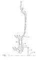
- Fig. 1 illustrates a circular rabbet surface 10 of a high pressure turbine forward air seal, generally designated by 12, having a radius 14 measured from a centerline 16 of the seal. If the rabbet surface 10 is machined to a radius 14 less than engineering specifications, it may be repaired by applying a high velocity oxy fuel (HVOF) thermal spray. However, a fillet 18 immediately adjacent the rabbet surface 10 is highly stressed and cannot withstand degradation associated with over spray. Accordingly, the fillet 18 must be masked to protect it from over spray while the rabbet surface 10 is coated with thermal spray.
- HVOF high velocity oxy fuel
- masking tapes may be used with lower velocity air plasma spray coating processes, these tapes cannot withstand the forces exerted by the HVOF thermal spray process.
- High temperature silicone putties designed for HVOF coating processes must be trimmed so they are positioned accurately enough to allow the coating to build up the rabbet surface 10 without allowing coating in the fillet 18. However, the trimming process may damage the component.
- thick one-piece metal masks i.e., masks having a thickness greater than 2.54 mm (0.1 inch)
- components such as the forward air seal 12 have shapes which prevent the use of these masks because the masks obstruct the thermal spray from reaching the rabbet surface 10.
- a mask assembly for protecting a portion of a workpiece from over spray while coating a preselected surface of the workpiece with thermal spray.
- the mask assembly comprises a sheet sized and shaped for covering the portion of the workpiece which the assembly is intended to protect and a support plate selectively mountable over the sheet while the surface is coated with thermal spray.
- the mask assembly comprises a clamp mountable on the support plate for selectively attaching the support plate to the workpiece thereby clamping the support plate and sheet in position over the portion of the workpiece.
- the present invention includes a method of masking a workpiece to protect a portion of the workpiece from over spray while coating a preselected surface of the workpiece with thermal spray.
- the method comprises the steps of selecting a sheet sized and shaped for covering the portion of the workpiece which the assembly is intended to protect and aligning the sheet with the portion of the workpiece so that an end of the sheet defines a boundary of the preselected surface of the workpiece.
- the method includes clamping the sheet to the portion of the workpiece to prevent the sheet from moving while coating the surface of the workpiece with thermal spray.
- the present invention includes a mask assembly for protecting a portion of a workpiece from over spray while coating a preselected surface of the workpiece with thermal spray.
- the mask assembly comprises a sheet having a thickness of less than about 2.54 mm (0.10 inch).
- the sheet is sized and shaped for covering the portion of the workpiece.
- the mask assembly comprises a clamp for selectively clamping the sheet to the workpiece in position over the portion of the workpiece.
- a mask assembly of the present invention is designated in its entirety by the reference number 20.
- the mask assembly 20 is used for protecting a portion of a workpiece such as a fillet 18 of a high pressure turbine forward air seal 12 from over spray while coating a preselected surface of the workpiece such as a circular rabbet surface 10 with thermal spray.
- the mask assembly 20 comprises a sheet, a support plate, a backing plate and a clamp, generally designated by 22, 24, 26 and 28, respectively.
- the sheet 22 is sized and shaped for covering the portion of the workpiece which the assembly 20 is intended to protect.
- a sheet 22 sized and shaped for covering the fillet 18 of the high pressure turbine forward air seal 12 would have a circular inner end 30 having a radius corresponding to the rabbet radius 14 so the inner end of the sheet would define one boundary of the surface of the air seal being coated.
- the inner end 30 is rounded as illustrated in Fig. 2 to avoid damaging the air seal 12.
- the sheet 22 also has an outer end 32 having a size and shape which are not critical because the outer end is spaced from the surface of the workpiece being sprayed.
- the outer end 32 is also circular and has a radius large enough to eliminate the potential for over spray to contact the workpiece outside the sheet 22 (e.g., about one inch larger than the inner radius).
- the sheet is segmented (e.g., in four segments) as illustrated in Fig. 3 for covering corresponding segments of the air seal 12.
- Each segment of the sheet 22 includes a plurality of holes 34 (e.g., six holes) positioned for alignment with bolt holes 36 extending through the air seal 12. These holes 34 are used to fasten the segments of the sheet 22 to the air seal 12 as will be explained in greater detail below.
- the support plate 24 is selectively mountable over the sheet 22 while the surface 10 is coated with thermal spray to support the sheet.
- the support plate 24 is spaced from the end 30 when mounted over the sheet 22 so the support plate does not obstruct the surface 10 of the air seal 12 during spraying.
- the support plate 24 includes a relieved edge 38 to provide access to the surface 10 of the air seal 12 so the support plate does not obstruct the surface while the surface is coated with thermal spray.
- the support plate 24 supports and protects the sheet 22 so that the sheet may be made from thinner material.
- the clamp 28 is mountable on the support plate 24 for selectively attaching the support plate to the air seal 12.
- the clamp 28 clamps the support plate 24 and sheet 22 in position over the portion of the workpiece being protected from over spray.
- the clamp 28 may have other configurations without departing from the scope of the present invention, in one embodiment the clamp 28 includes a stud 40 mounted on the support plate 24.
- the stud 40 is sized and positioned on the support plate 24 to be received within the bolt holes 34, 36 extending through the sheet 22 and the air seal 12, as well as bolt holes 42 extending through the backing plate 28 to fasten the assembly 20 to the air seal.
- a nut 44 is threaded on the stud 40 to hold the assembly 20 in position on the air seal 12. As illustrated in Fig.
- the stud 40 has an outer diameter 50 smaller than a diameter 52 of the bolt hole 34 in the sheet 22 and a diameter 54 of the bolt hole 36 in the air seal 12, thus providing clearance so the position of the sheet can be adjusted until the inner end 30 touches the air seal.
- the backing plate 26 protects the air seal 12 from damage as the nut 44 is tightened.
- High temperature masking tape 62 may be used to cover the end gaps 60, between the segments 22 to protect the air seal 12 from over spray.
- the masking tape is FLUORGLAS7 2905-7 tape available from Furon Company Corporation of Website of Georgia.
- FLUORGLAS is a U.S. federally registered trademark owned by Furon Co. Corp. This masking tape has been found to have sufficient durability to withstand HVOF thermal spray over the small areas required to cover the end gaps 60.
- the gaps 60 are very narrow (e.g., 1 mm (0.040 inch)) positioning and/or trimming the tape to fit the gaps is fairly easy to accomplish without damaging the air seal 12 even with minimal operator skill.
- the sheet 22 is formed using conventional manufacturing techniques such as electrical discharge machining so it is sized and shaped for covering the portion of the workpiece which the assembly is intended to protect. As illustrated in Fig. 2 , the sheet 22 is formed from raw sheet material having a preselected thickness 70 (e.g., 0.020 inch) so the assembly 10 obstructs only the portion of the workpiece it is intended to protect without obstructing the portion of the workpiece intended to be coated. Although other materials may be used without departing from the scope of the present invention, in one embodiment the raw sheet material used to form the sheet is a cold rolled steel having a thickness less than about 2.54 mm (0.100 inch). Other thicknesses may be used without departing from the scope of the present invention provided the sheet material is thick enough to withstand thermal spray.
- a preselected thickness 70 e.g., 0.020 inch
- the sheet 22 is aligned with the fillet 18 of the air seal 12 so that the inner end 30 of the sheet defines a boundary of the surface 10 being coated.
- the studs 40 of the clamp 28 are inserted through the holes 34 in the sheet 22, and the backing plate 26 is installed over the ends of the studs.
- the nuts 44 are threaded onto the studs 40 and tightened to clamp the sheet 22 over the fillet 18 to prevent the sheet from moving while coating the surface 10 of the air seal 12 with thermal spray.
- the air seal surface 10 may be coated with thermal spray using conventional processes. After the air seal 12 is sprayed, the assembly 20 may be removed and reused. If the sheet 22 becomes damaged, it can easily and inexpensively be replaced by forming a new one. Because the other components of the assembly 20 are made from heavier stock, the are less susceptible to damage.
Landscapes
- Chemical & Material Sciences (AREA)
- Engineering & Computer Science (AREA)
- Physics & Mathematics (AREA)
- Plasma & Fusion (AREA)
- Chemical Kinetics & Catalysis (AREA)
- Materials Engineering (AREA)
- Mechanical Engineering (AREA)
- Metallurgy (AREA)
- Organic Chemistry (AREA)
- Coating By Spraying Or Casting (AREA)
- Details Or Accessories Of Spraying Plant Or Apparatus (AREA)
Claims (7)
- Abdeckanordnung (20) zum Schutz eines Abschnittes (18) eines Werkstückes (12) vor Überspritzen, während eine vorgewählte Oberfläche (10) des Werkstückes (12) mit einem thermischen Spritzmaterial beschichtet wird, wobei die Abdeckanordnung (20) aufweist:ein Blech (22), das für die Abdeckung des Abschnittes (18) des Werkstückes (12) bemessen und geformt ist, welchen die Anordnung (20) schützen soll;eine Unterstützungsplatte (24), die wahlweise über dem Blech (22) befestigt werden kann, während die Oberfläche (10) mit thermischem Spritzmaterial beschichtet wird; undeine Klemmvorrichtung (28), die auf der Unterstützungsplatte (24) befestigt werden kann, um wahlweise die Unterstützungsplatte (24) an dem Werkstück (12) anzubringen und dadurch die Unterstützungsplatte (24) und das Blech (22) in Position über dem Abschnitt (18) des Werkstückes (12) festzuklemmen, dadurch gekennzeichnet, dass;das Werkstück (12) und das Blech (22) ringförmig sind, und das Blech (22) in Segmenten ausgebildet ist, um entsprechende Segmente des ringförmigen Werkstückes (12) abzudecken.
- Abdeckanordnung (20) nach Anspruch 1, wobei das Blech (22) ein Ende (30) enthält, das wenigstens teilweise eine Begrenzung der vorgewählten Oberfläche (10) des Werkstückes (12) definiert und die Unterstützungsplatte (24) von dem Ende (30) beabstandet ist, wenn sie über dem Blech (22) so befestigt ist, dass die vorgewählte Oberfläche (10) des Werkstückes (12) durch die Unterstützungsplatte (24) während des Sprühvorgangs nicht verdeckt ist.
- Abdeckanordnung (20) nach Anspruch 2, wobei die Unterstützungsplatte (24) eine ausgesparte Kante (38) enthält, um einen Zugang zu der vorgewählten Oberfläche (10) des Werkstückes (12) bereitzustellen, so dass die vorgewählte Oberfläche (10) durch die Unterstützungsplatte (24) nicht verdeckt ist, während die Oberfläche (10) mit thermischem Spritzmaterial beschichtet wird.
- Abdeckanordnung (20) nach Anspruch 1, wobei das Werkstück (12) ein Loch (36) in Abstand von der vorgewählten Oberfläche (10) des Werkstückes (12) enthält, und die Klemmvorrichtung (28) ferner ein sich aus der Unterstützungsplatte (24) erstreckendes Befestigungselement (40) aufweist, das für die Aufnahme in dem Loch (36) in dem Werkstück (12) bemessen und positioniert ist.
- Abdeckanordnung (20) nach Anspruch 4, wobei das Befestigungselement einen sich aus der Unterstützungsplatte (24) erstreckenden Schraubbolzen (40) aufweist und die Klemmvorrichtung (28) ferner eine Mutter (44) aufweist, die mit dem Schraubbolzen (40) verschraubt werden kann, um die Abdeckanordnung (20) an dem Werkstück (12) zu befestigen.
- Abdeckanordnung (20) nach Anspruch 5, welche ferner eine Verstärkungsplatte (26) aufweist, die zwischen der Mutter (44) und dem Werkstück (12) montiert werden kann, um das Werkstück (12) vor Beschädigung zu schützen.
- Abdeckanordnung (20) nach Anspruch 1, wobei die Segmente des Bleches (22) durch Endspalte (60) in Abstand angeordnet sind, die sich radial entlang dem Abschnitt (18) des Werkstückes (12) erstrecken, und die Anordnung (20) ferner ein Abdeckband (62) aufweist, um die Endspalte (60) zwischen den Segmenten zum Schutz des Werkstücks (12) vor Überspritzen abzudecken.
Applications Claiming Priority (2)
| Application Number | Priority Date | Filing Date | Title |
|---|---|---|---|
| US954774 | 2001-09-18 | ||
| US09/954,774 US6645299B2 (en) | 2001-09-18 | 2001-09-18 | Method and assembly for masking |
Publications (2)
| Publication Number | Publication Date |
|---|---|
| EP1293584A1 EP1293584A1 (de) | 2003-03-19 |
| EP1293584B1 true EP1293584B1 (de) | 2008-07-09 |
Family
ID=25495908
Family Applications (1)
| Application Number | Title | Priority Date | Filing Date |
|---|---|---|---|
| EP02256472A Expired - Lifetime EP1293584B1 (de) | 2001-09-18 | 2002-09-18 | Verfahren und Vorrichtung zum Abdecken |
Country Status (3)
| Country | Link |
|---|---|
| US (1) | US6645299B2 (de) |
| EP (1) | EP1293584B1 (de) |
| DE (1) | DE60227465D1 (de) |
Families Citing this family (15)
| Publication number | Priority date | Publication date | Assignee | Title |
|---|---|---|---|---|
| FR2863191B1 (fr) * | 2003-12-04 | 2007-04-20 | Snecma Moteurs | Masque de protection pour le traitement de surface d'aubes de turbomachines |
| TW200718805A (en) * | 2005-11-07 | 2007-05-16 | United Technologies Corp | Coating methods and apparatus |
| DE102008048127A1 (de) | 2008-09-20 | 2010-03-25 | Mtu Aero Engines Gmbh | Vorrichtung und Verfahren zum Maskieren einer Bauteilzone |
| DE102008053394A1 (de) * | 2008-10-27 | 2010-04-29 | Mtu Aero Engines Gmbh | Vorrichtung zum partiellen Abdecken einer Bauteilzone |
| DE102008056652A1 (de) * | 2008-11-10 | 2010-05-12 | Mtu Aero Engines Gmbh | Maske für das kinetische Kaltgaskompaktieren |
| US8967078B2 (en) * | 2009-08-27 | 2015-03-03 | United Technologies Corporation | Abrasive finish mask and method of polishing a component |
| EP2309016B1 (de) * | 2009-10-06 | 2012-10-03 | Siemens Aktiengesellschaft | Verfahren und Anordnung für ein Sprühbeschichtungsverfahren |
| US20130136864A1 (en) * | 2011-11-28 | 2013-05-30 | United Technologies Corporation | Passive termperature control of hpc rotor coating |
| US8985049B2 (en) | 2011-12-29 | 2015-03-24 | General Electric Company | Pressure maskers and pressure masking systems |
| CN104769148B (zh) * | 2012-11-07 | 2016-11-23 | 阿海珐核能公司 | 用于在遮掩部分的同时热化学处理部件的方法及相应掩模 |
| US9855576B2 (en) | 2015-08-19 | 2018-01-02 | Honda Motor Co., Ltd. | Paint masking system and method |
| WO2017081098A1 (de) | 2015-11-12 | 2017-05-18 | Oerlikon Metco Ag, Wohlen | Verfahren zur maskierung eines bauteils welches mit einer thermischen spritzschicht beschichtet werden soll |
| CN112553557A (zh) * | 2020-11-10 | 2021-03-26 | 中国航发北京航空材料研究院 | 一种带叶片的槽形零件热喷涂防护方法 |
| DE202021105511U1 (de) | 2021-10-12 | 2023-02-23 | Weidplas Gmbh | Vorrichtung zum Maskieren eines Bauteils und Vorrichtung zum Beschichten eines Bauteils |
| CN116638445B (zh) * | 2022-02-16 | 2025-11-18 | 昆山三禾美德电子有限公司 | 一种覆盖装置及采用该覆盖装置的工件局部喷砂装置 |
Family Cites Families (21)
| Publication number | Priority date | Publication date | Assignee | Title |
|---|---|---|---|---|
| US3102053A (en) * | 1960-08-16 | 1963-08-27 | Robert B Way | Automatic painting machine |
| US4263341A (en) * | 1978-12-19 | 1981-04-21 | Western Electric Company, Inc. | Processes of making two-sided printed circuit boards, with through-hole connections |
| US4822108A (en) * | 1984-05-14 | 1989-04-18 | Deere & Company | Row straddling dual wheels for a harvester |
| JPS62116761A (ja) * | 1985-11-15 | 1987-05-28 | Sanyo Electric Co Ltd | マスキング装置 |
| JPS62164867A (ja) * | 1986-01-14 | 1987-07-21 | Mitsubishi Electric Corp | 成膜マスク装置 |
| NO171518C (no) * | 1990-10-12 | 1993-03-24 | Krageboen Tor Birger | Anordning ved akseltetning omfattende en pakkboks |
| US5286573A (en) * | 1990-12-03 | 1994-02-15 | Fritz Prinz | Method and support structures for creation of objects by layer deposition |
| US5195243A (en) * | 1992-02-28 | 1993-03-23 | General Motors Corporation | Method of making a coated porous metal panel |
| US5527586A (en) * | 1992-03-18 | 1996-06-18 | Printron, Inc. | Apparatus and method for depositing metal particles on a dielectric substrate |
| US5632529A (en) | 1995-04-18 | 1997-05-27 | Hayes Wheels International, Inc. | Plated vehicle wheel having non-plated tire bead seats |
| US5617990A (en) * | 1995-07-03 | 1997-04-08 | Micron Electronics, Inc. | Shield and method for selective wave soldering |
| US5786028A (en) | 1996-09-05 | 1998-07-28 | Cantwell; Jay S. | Masking tape and method |
| US5902647A (en) | 1996-12-03 | 1999-05-11 | General Electric Company | Method for protecting passage holes in a metal-based substrate from becoming obstructed, and related compositions |
| US5888301A (en) * | 1997-05-22 | 1999-03-30 | Jamieson; James W. | Tile-holding fixture for adhesive application |
| US5915743A (en) | 1997-06-30 | 1999-06-29 | The Boeing Company | Metal spray tool repair system |
| US6037004A (en) * | 1997-12-19 | 2000-03-14 | United Technologies Corporation | Shield and method for protecting an airfoil surface |
| US5916638A (en) | 1997-12-19 | 1999-06-29 | United Technologies Corporation | Method for applying a coating to the tip of a flow directing assembly |
| US6273676B1 (en) * | 1998-06-17 | 2001-08-14 | United Technologies Corporation | Method and assembly for masking a flow directing assembly |
| US6109873A (en) | 1998-06-17 | 2000-08-29 | United Technologies Corporation | Shield for masking a flow directing assembly |
| US6060117A (en) | 1998-08-31 | 2000-05-09 | Ford Global Technologies, Inc. | Making and using thermal spray masks carrying thermoset epoxy coating |
| US6146489A (en) * | 1998-11-19 | 2000-11-14 | General Electric Company | Method and apparatus for depositing scintillator material on radiation imager |
-
2001
- 2001-09-18 US US09/954,774 patent/US6645299B2/en not_active Expired - Fee Related
-
2002
- 2002-09-18 EP EP02256472A patent/EP1293584B1/de not_active Expired - Lifetime
- 2002-09-18 DE DE60227465T patent/DE60227465D1/de not_active Expired - Lifetime
Also Published As
| Publication number | Publication date |
|---|---|
| EP1293584A1 (de) | 2003-03-19 |
| US20030054104A1 (en) | 2003-03-20 |
| US6645299B2 (en) | 2003-11-11 |
| DE60227465D1 (de) | 2008-08-21 |
Similar Documents
| Publication | Publication Date | Title |
|---|---|---|
| EP1293584B1 (de) | Verfahren und Vorrichtung zum Abdecken | |
| EP1077090B1 (de) | Vorrichtung und Verfahren zum partiellen Abdecken von Motorblöcken bei ihrer Beschichtung durch thermisches Spritzen | |
| EP0998593B1 (de) | Verfahren zur herstellung eines durchbrochenen artikels zur wiederbeschichtung | |
| EP0925845B1 (de) | Schild und Verfahren zum Schützen der Oberfläche eines Werkstückes mit einem Flügelprofil | |
| US6273676B1 (en) | Method and assembly for masking a flow directing assembly | |
| US6109873A (en) | Shield for masking a flow directing assembly | |
| US20110076405A1 (en) | Hole drilling with close proximity backwall | |
| MXPA04012145A (es) | Mascara de proteccion para tratamiento superficial de cuchillas de turbomaquina. | |
| EP2027932B1 (de) | Maskenfixierung für ein Beschichtungsverfahren | |
| EP0925844A2 (de) | Verfahren zum Auftrag einer Beschichtung auf die Spitze von Leitschaufeln | |
| EP1103627A2 (de) | Verfahren zur Herstellung einer Wärmedämmschicht | |
| US20030232139A1 (en) | Shield and method for spraying coating on a surface | |
| US8323409B2 (en) | Systems and methods for forming components with thermal barrier coatings | |
| CN113502446A (zh) | 快速翻遍和快换式的喷涂防护夹具和喷涂方法 | |
| US8468969B2 (en) | Dimensionally stable durable thermal spray masking system | |
| EP2309016B1 (de) | Verfahren und Anordnung für ein Sprühbeschichtungsverfahren | |
| US8211506B2 (en) | Coating methods and apparatus using pre-formed ceramic mask | |
| US6561872B2 (en) | Method and apparatus for stripping coating | |
| CN116851163A (zh) | 喷涂夹具及喷涂方法 | |
| EP0965390B1 (de) | Verschlusselement für eine Abdeckung einer Turbinenleitschaufel | |
| US12428978B2 (en) | Equipment for treating an aircraft turbomachine component | |
| EP1801360B1 (de) | Verfahren und Vorrichtung zur Herstellung eines Bauteils einer Turbine | |
| CN116038245B (zh) | 转台加工防护方法 | |
| AU2024402023A1 (en) | Rigid masking devices and methods for in-situ application of a spray-applied coating material onto a substrate surface | |
| CN121290281A (zh) | 一种风扇轴的吹砂防护夹具及方法 |
Legal Events
| Date | Code | Title | Description |
|---|---|---|---|
| PUAI | Public reference made under article 153(3) epc to a published international application that has entered the european phase |
Free format text: ORIGINAL CODE: 0009012 |
|
| AK | Designated contracting states |
Kind code of ref document: A1 Designated state(s): AT BE BG CH CY CZ DE DK EE ES FI FR GB GR IE IT LI LU MC NL PT SE SK TR |
|
| AX | Request for extension of the european patent |
Extension state: AL LT LV MK RO SI |
|
| 17P | Request for examination filed |
Effective date: 20030919 |
|
| AKX | Designation fees paid |
Designated state(s): DE FR GB |
|
| 17Q | First examination report despatched |
Effective date: 20040407 |
|
| GRAP | Despatch of communication of intention to grant a patent |
Free format text: ORIGINAL CODE: EPIDOSNIGR1 |
|
| GRAS | Grant fee paid |
Free format text: ORIGINAL CODE: EPIDOSNIGR3 |
|
| GRAA | (expected) grant |
Free format text: ORIGINAL CODE: 0009210 |
|
| AK | Designated contracting states |
Kind code of ref document: B1 Designated state(s): DE FR GB |
|
| REG | Reference to a national code |
Ref country code: GB Ref legal event code: FG4D |
|
| REF | Corresponds to: |
Ref document number: 60227465 Country of ref document: DE Date of ref document: 20080821 Kind code of ref document: P |
|
| PLBE | No opposition filed within time limit |
Free format text: ORIGINAL CODE: 0009261 |
|
| STAA | Information on the status of an ep patent application or granted ep patent |
Free format text: STATUS: NO OPPOSITION FILED WITHIN TIME LIMIT |
|
| 26N | No opposition filed |
Effective date: 20090414 |
|
| PGFP | Annual fee paid to national office [announced via postgrant information from national office to epo] |
Ref country code: GB Payment date: 20090701 Year of fee payment: 8 |
|
| PGFP | Annual fee paid to national office [announced via postgrant information from national office to epo] |
Ref country code: DE Payment date: 20090929 Year of fee payment: 8 |
|
| GBPC | Gb: european patent ceased through non-payment of renewal fee |
Effective date: 20100918 |
|
| REG | Reference to a national code |
Ref country code: FR Ref legal event code: ST Effective date: 20110531 |
|
| REG | Reference to a national code |
Ref country code: DE Ref legal event code: R119 Ref document number: 60227465 Country of ref document: DE Effective date: 20110401 |
|
| PG25 | Lapsed in a contracting state [announced via postgrant information from national office to epo] |
Ref country code: FR Free format text: LAPSE BECAUSE OF NON-PAYMENT OF DUE FEES Effective date: 20100930 Ref country code: DE Free format text: LAPSE BECAUSE OF NON-PAYMENT OF DUE FEES Effective date: 20110401 |
|
| PG25 | Lapsed in a contracting state [announced via postgrant information from national office to epo] |
Ref country code: GB Free format text: LAPSE BECAUSE OF NON-PAYMENT OF DUE FEES Effective date: 20100918 |
|
| PGFP | Annual fee paid to national office [announced via postgrant information from national office to epo] |
Ref country code: FR Payment date: 20091006 Year of fee payment: 8 |