EP1293614A2 - Siege d'aisances comprenant un systeme modulaire d'evacuation sous vide - Google Patents
Siege d'aisances comprenant un systeme modulaire d'evacuation sous vide Download PDFInfo
- Publication number
- EP1293614A2 EP1293614A2 EP01945351A EP01945351A EP1293614A2 EP 1293614 A2 EP1293614 A2 EP 1293614A2 EP 01945351 A EP01945351 A EP 01945351A EP 01945351 A EP01945351 A EP 01945351A EP 1293614 A2 EP1293614 A2 EP 1293614A2
- Authority
- EP
- European Patent Office
- Prior art keywords
- tank
- module
- toilet
- valve
- bowl
- Prior art date
- Legal status (The legal status is an assumption and is not a legal conclusion. Google has not performed a legal analysis and makes no representation as to the accuracy of the status listed.)
- Withdrawn
Links
- 239000002351 wastewater Substances 0.000 claims abstract description 9
- XLYOFNOQVPJJNP-UHFFFAOYSA-N water Substances O XLYOFNOQVPJJNP-UHFFFAOYSA-N 0.000 claims description 14
- 238000004140 cleaning Methods 0.000 claims description 7
- 238000009434 installation Methods 0.000 abstract description 8
- 238000012423 maintenance Methods 0.000 abstract description 8
- 238000007792 addition Methods 0.000 description 2
- 238000013461 design Methods 0.000 description 2
- 108010053481 Antifreeze Proteins Proteins 0.000 description 1
- 230000002528 anti-freeze Effects 0.000 description 1
- 230000015556 catabolic process Effects 0.000 description 1
- 238000004891 communication Methods 0.000 description 1
- 230000008878 coupling Effects 0.000 description 1
- 238000010168 coupling process Methods 0.000 description 1
- 238000005859 coupling reaction Methods 0.000 description 1
- 230000008014 freezing Effects 0.000 description 1
- 238000007710 freezing Methods 0.000 description 1
- 230000006872 improvement Effects 0.000 description 1
- 238000010348 incorporation Methods 0.000 description 1
- 238000004519 manufacturing process Methods 0.000 description 1
- 238000000034 method Methods 0.000 description 1
- 238000012986 modification Methods 0.000 description 1
- 230000004048 modification Effects 0.000 description 1
- 230000008569 process Effects 0.000 description 1
- 238000005086 pumping Methods 0.000 description 1
- 230000001360 synchronised effect Effects 0.000 description 1
Images


Classifications
-
- E—FIXED CONSTRUCTIONS
- E03—WATER SUPPLY; SEWERAGE
- E03F—SEWERS; CESSPOOLS
- E03F1/00—Methods, systems, or installations for draining-off sewage or storm water
- E03F1/006—Pneumatic sewage disposal systems; accessories specially adapted therefore
Definitions
- the present invention relates to a toilet with modular vacuum-disposal system which includes a toilet bowl, a tank for the reception of a quantity of wastewater, a cut-off valve between the bowl outlet and the tank inlet, a vacuum generator connected to the tank, a tank inlet valve for the inlet of pressurised air to the tank, a tank discharge valve, a plurality of electrically-operated valves and control means.
- the toilets and their associated disposal systems have been made more compact, and a disposal system has been developed which has an intermediate wastewater tank associated with each toilet, inside which it is possible to cause selectively either a vacuum to suck in a charge of wastewater contained in the toilet, or a pressure higher than atmospheric pressure in order to expel the contents from the tank.
- This partial vacuum and partial pressure design has reduced the consumption and size of the devices of the disposal system; however, especially while trying to make the systems more compact so that they occupy less space, assembly and maintenance have been made more difficult. For example, when one of the parts of the system has to be replaced or repaired, a large section of the assembly has to be disassembled, an operation which can take time, and it further requires that the maintenance personnel carry a high number of replacement parts.
- installation of the equipment is also a laborious operation, since the parts have to be fitted one after the other and all the connections made between them.
- the object of the present invention is to solve the mentioned drawbacks by developing a toilet with modular vacuum-disposal system which is compact and occupies a small space, while being at the same easy and inexpensive to assemble and maintain.
- Another object is that the system can be adapted to the space available in each case, and that after installation it allows the addition of further modules, for example in order to increase its performance.
- the toilet with vacuum-disposal system of this invention is characterised in that the aforesaid elements are grouped into at least a first module which includes the toilet bowl and the cut-off valve at the outlet from the toilet bowl, a second module which includes the tank, the vacuum generator, the tank inlet valve for pressurised air and the tank discharge valve, and a third module which includes said electrically-operated valves, and in that within each module the elements are joined together and have fixed connections between each other, while between one module and another there are fast-on hydraulic and pneumatic connections.
- This modular system occupies a small space and at the same time allows simple and fast installation and maintenance operations. It thus solves the disadvantages mentioned in relation with installation and maintenance of the equipment, while it also presents other advantages, such as the ease with which the equipment can be extended after installation in order to improve its performance, and a remarkable improvement in industrialisation of the system, thanks to the possibility of manufacturing some basic modules and combining them in different ways according to the specific needs of each case.
- the modularity of the equipment also facilitates the incorporation of additional functions, such as an anti-freeze module, in cases where such are necessary.
- the equipment further includes a fourth module, made up of all the control elements, and a fifth module which includes a pump for discharge of cleaning water to the toilet bowl.
- each module also includes at least some of the accessory elements of its components.
- the second module is mounted on a supporting frame which is attached in a suitable location, and the first module is mounted on the second module by means of two side supports, the toilet bowl being mounted adjacent to the tank.
- the module with the bowl and its outlet valve which is one of the most prone to fail, can be easily removed for replacement.
- Figure 1 is a schematic view of a toilet with modular vacuum-disposal system in accordance with the invention, with its parts separated;
- Figure 2 is a side elevation view of the system of Figure 1, with some modules assembled;
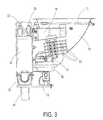
- Figure 3 is a view similar to that of Figure 2, to which the pneumatic module and the water pump module have been added.
- FIG 1 illustrates schematically the main elements of the toilet system of the invention and the connections between them.
- the system comprises: a first module 1 which includes the toilet bowl 10, a cleaning water supply system 11, a valve 12 associated with the outlet from the bowl, and its accessories; a second module 2 made up of a tank 20, its discharge valve 21 and the vacuum generating ejector 22, for creating a vacuum in the tank in order to carry the contents of the toilet bowl towards the tank; a pneumatic module 3, which includes a number of electrically-operated valves for driving the various elements; a control module 4, which contains all the electrical and electronic controls of the system; and a pump module 5, consisting in the pump 50 which discharges the cleaning water into the bowl and its associated accessories.
- the tank 20 has a capacity of about 5 litres (although this characteristic is not restrictive), and it constitutes an intermediate tank between the bowl and a larger tank (not shown) which can be connected to several toilets, in such a way that the tank 20 is emptied at intervals and the wastewater goes on to the final tank.
- the pumping module 5 is not a part of the disposal system as such, but it is advisable also to integrate it into the installation; it is also connected to the pneumatic module 4 and is housed physically adjacent to the other modules.
- the toilet includes a base frame 6 to which is fixed the intermediate tank module 2; on the latter are mounted the other modules of the system, using for example brackets, flanges and bolts.
- the various modules are connected to each other by means of suitable pipes: the pump 50 is connected through respective water pipes L1 and L2 to the water network (not shown) and to the system 11 of water supply to the toilet bowl; the bowl outlet valve 12, once the system has been fitted, is connected directly to the tank inlet 20; and the electrically-operated valves of the pneumatic module 3 are connected through pneumatic lines L3 to L7 to the various elements they have to actuate.
- the module 3 is connected through a line L8 to a source of air under pressure.
- control module 4 has cables for connection to the electrically-operated valves of module 3, to auxiliary elements of the system, such as sensors and the like, and to the button for actuating discharge of water into the toilet bowl.
- auxiliary elements of the system such as sensors and the like
- button for actuating discharge of water into the toilet bowl are conventional and have not been shown, in order to avoid complications in the figure.
- FIG. 2 shows the system with the two main modules fitted.
- Module 1 includes, in addition to the toilet bowl 10 and the cut-off valve 12 for opening and closing passage of wastewater from the bowl 10 to the tank 20, a lubricator 13.
- the valve 12 includes a corresponding actuator (not visible in the figure, since it is behind the valve itself) connected to the pneumatic module 3.
- the cleaning water feed pipe 11 is installed at the upper part of the bowl, forming part of module 1. It has a fast-on connection 14 to line L2 for attachment to the pump 50, and branch lines 15 for supplying water to various points of the bowl.
- Module 1 is attached on module 2 of the tank through side supports 16, one of which is visible in Figures 2 and 3.
- Module 2 with the intermediate tank 20, which is mounted on the supporting frame 6, also includes the ejector 22, a pressurised-air inlet valve 23, with which are associated a sensor and pressure regulator, and a discharge valve 21 for draining the tank 20.
- the ejector 22 and the inlet valve 23 are mounted on the tank 20, while the cut-off valve 21 is connected at the lower part thereof.
- the outlet pipe 24 from the valve 21 is connected to a discharge pipe leading to another tank (not shown) of larger capacity, to which several toilets can be connected.
- the function of the ejector 22 is to create a temporary vacuum in the tank, synchronised with the opening of the valve 12 and with the discharge of cleaning water into the toilet bowl, for the purpose of carrying the wastewater from the bowl to the tank.
- the function of the pressurised-air inlet valve 23 is to allow the entry of air under pressure into the tank 20, in synchronisation with opening of the discharge valve 21, in order to drain the tank 20.
- the pressure regulator associated with the valve 23 limits the pressure in the tank to a predetermined value, such as 2 bar.
- FIG 3 shows the toilet with all modules fitted to the system, except for the control module 4, which would normally be installed separately from the toilet.
- the pneumatic module 3 and the pump module 5 are mounted one on top of the other, on one side of the toilet bowl 10.
- the modular toilet described is mounted onto a railway carriage using the pre-assembled modules described. Firstly, module 2 of the tank is installed, and then module 1 of the bowl 10 is mounted on top of it, followed by the pump module 5 and the pneumatic module 3. The modules are attached using supports and bolted fittings easy to access.
- the operation of the system is as follows.
- the pump 50 pumps water to the bowl through the feed pipe 11; at the same time, the bowl outlet valve 12 opens and the ejector 22 actuates to create a depression in the tank in order to "suck" the wastewater from the bowl into the tank.
- the tank 20 is drained.
- the discharge valve 21 is opened and pressure is provided to the tank through the air inlet valve 23.
- control means 4 on the basis of programming parameters and reading of suitable sensors.
Landscapes
- Health & Medical Sciences (AREA)
- Life Sciences & Earth Sciences (AREA)
- Engineering & Computer Science (AREA)
- Hydrology & Water Resources (AREA)
- Public Health (AREA)
- Water Supply & Treatment (AREA)
- Sanitary Device For Flush Toilet (AREA)
- Vehicle Waterproofing, Decoration, And Sanitation Devices (AREA)
Applications Claiming Priority (3)
| Application Number | Priority Date | Filing Date | Title |
|---|---|---|---|
| ES200001568U ES1046525Y (es) | 2000-06-12 | 2000-06-12 | Inodoro con sistema modular de evacuacion por vacio. |
| ES200001568U | 2000-06-12 | ||
| PCT/ES2001/000236 WO2001096677A2 (fr) | 2000-06-12 | 2001-06-08 | Siege d'aisances comprenant un systeme modulaire d'evacuation sous vide |
Publications (1)
| Publication Number | Publication Date |
|---|---|
| EP1293614A2 true EP1293614A2 (fr) | 2003-03-19 |
Family
ID=8494000
Family Applications (1)
| Application Number | Title | Priority Date | Filing Date |
|---|---|---|---|
| EP01945351A Withdrawn EP1293614A2 (fr) | 2000-06-12 | 2001-06-08 | Siege d'aisances comprenant un systeme modulaire d'evacuation sous vide |
Country Status (6)
| Country | Link |
|---|---|
| US (1) | US6625822B2 (fr) |
| EP (1) | EP1293614A2 (fr) |
| CN (1) | CN1383411A (fr) |
| CA (1) | CA2381702A1 (fr) |
| ES (1) | ES1046525Y (fr) |
| WO (1) | WO2001096677A2 (fr) |
Cited By (5)
| Publication number | Priority date | Publication date | Assignee | Title |
|---|---|---|---|---|
| WO2006040138A1 (fr) * | 2004-10-13 | 2006-04-20 | Evac Gmbh | Toilettes a vide destinees a des vehicules |
| EP2371654A3 (fr) * | 2010-03-18 | 2013-01-16 | Siemens Aktiengesellschaft | Véhicule ferroviaire doté d'un dispositif sanitaire |
| EP2826409A1 (fr) * | 2013-07-19 | 2015-01-21 | Sandro Ordiligi | Dispositif de séchage à main |
| EP3321439A1 (fr) * | 2016-11-15 | 2018-05-16 | Alte Technologies S.L.U. | Système de transfert de déchets pour toilettes d'un véhicule de transport public |
| WO2020043416A1 (fr) * | 2018-08-31 | 2020-03-05 | Aco Severin Ahlmann Gmbh & Co. Kg | Dispositif d'eaux usées sous vide, procédé et unité de commande électronique pour commander un dispositif d'eaux usées sous vide |
Families Citing this family (10)
| Publication number | Priority date | Publication date | Assignee | Title |
|---|---|---|---|---|
| CN100370083C (zh) * | 2005-08-04 | 2008-02-20 | 曹保琪 | 一种真空厕所系统 |
| EA016706B1 (ru) * | 2009-04-02 | 2012-06-29 | Ооо Нпц "Экспресс" | Туалетная система для пассажирского железнодорожного вагона |
| CN103318210A (zh) * | 2013-06-27 | 2013-09-25 | 宁波南车时代传感技术有限公司 | 用于动车真空集便器的水增压装置 |
| DE102014202750A1 (de) * | 2014-02-14 | 2015-08-20 | Siemens Aktiengesellschaft | Sanitäreinrichtung für ein Schienenfahrzeug |
| CN105644463B (zh) * | 2015-12-29 | 2021-10-29 | 宜为客有限公司 | 用于交通工具的真空便器系统 |
| CN105523054B (zh) * | 2015-12-30 | 2018-12-04 | 长春市朗瑞斯铁路装备有限公司 | 一种真空排污式集便系统 |
| CN105564455A (zh) * | 2016-01-07 | 2016-05-11 | 长春市朗瑞斯铁路装备有限公司 | 紧凑式集便系统 |
| CN110015312A (zh) * | 2019-04-25 | 2019-07-16 | 中车青岛四方机车车辆股份有限公司 | 列车及列车供水系统 |
| CN112112238A (zh) * | 2020-08-21 | 2020-12-22 | 宁波中车时代电气设备有限公司 | 一种紧凑型中转式真空座便器 |
| CN112681478A (zh) * | 2020-12-15 | 2021-04-20 | 南京航空航天大学 | 基于真空和加压技术的城市废水输送系统 |
Family Cites Families (6)
| Publication number | Priority date | Publication date | Assignee | Title |
|---|---|---|---|---|
| ES8607847A3 (es) * | 1985-06-11 | 1986-06-01 | Ferre Nunell Eduardo | Equipo para la evacuacion de residuos en instalaciones de inodoros en ferrocarriles |
| US4713847B1 (en) * | 1987-02-02 | 1996-05-28 | Waertsilae Oy Ab | Vacuum toilet system |
| FI83797C (fi) * | 1988-10-05 | 1991-08-26 | Nesite Oy | Avloppssystem. |
| US5604938A (en) * | 1992-04-02 | 1997-02-25 | Norcan Aircraft Corporation | Vacuum flush waste disposal system for railcars |
| DK171589B1 (da) * | 1996-01-19 | 1997-02-10 | Abb Daimler Benz Transp | Sanitetscelle |
| FI100547B (fi) * | 1996-07-09 | 1997-12-31 | Evac Int Oy | Alipaineklosetti |
-
2000
- 2000-06-12 ES ES200001568U patent/ES1046525Y/es not_active Expired - Lifetime
-
2001
- 2001-06-08 CN CN01801675A patent/CN1383411A/zh active Pending
- 2001-06-08 WO PCT/ES2001/000236 patent/WO2001096677A2/fr not_active Ceased
- 2001-06-08 CA CA002381702A patent/CA2381702A1/fr not_active Abandoned
- 2001-06-08 US US10/049,467 patent/US6625822B2/en not_active Expired - Fee Related
- 2001-06-08 EP EP01945351A patent/EP1293614A2/fr not_active Withdrawn
Non-Patent Citations (1)
| Title |
|---|
| See references of WO0196677A2 * |
Cited By (6)
| Publication number | Priority date | Publication date | Assignee | Title |
|---|---|---|---|---|
| WO2006040138A1 (fr) * | 2004-10-13 | 2006-04-20 | Evac Gmbh | Toilettes a vide destinees a des vehicules |
| CN100415570C (zh) * | 2004-10-13 | 2008-09-03 | 埃瓦克有限公司 | 用于车辆的真空马桶 |
| EP2371654A3 (fr) * | 2010-03-18 | 2013-01-16 | Siemens Aktiengesellschaft | Véhicule ferroviaire doté d'un dispositif sanitaire |
| EP2826409A1 (fr) * | 2013-07-19 | 2015-01-21 | Sandro Ordiligi | Dispositif de séchage à main |
| EP3321439A1 (fr) * | 2016-11-15 | 2018-05-16 | Alte Technologies S.L.U. | Système de transfert de déchets pour toilettes d'un véhicule de transport public |
| WO2020043416A1 (fr) * | 2018-08-31 | 2020-03-05 | Aco Severin Ahlmann Gmbh & Co. Kg | Dispositif d'eaux usées sous vide, procédé et unité de commande électronique pour commander un dispositif d'eaux usées sous vide |
Also Published As
| Publication number | Publication date |
|---|---|
| US20030074728A1 (en) | 2003-04-24 |
| ES1046525U (es) | 2001-01-01 |
| CN1383411A (zh) | 2002-12-04 |
| US6625822B2 (en) | 2003-09-30 |
| WO2001096677A2 (fr) | 2001-12-20 |
| WO2001096677A3 (fr) | 2002-04-11 |
| ES1046525Y (es) | 2001-06-01 |
| CA2381702A1 (fr) | 2001-12-20 |
Similar Documents
| Publication | Publication Date | Title |
|---|---|---|
| US6625822B2 (en) | Toilet with a modular vacuum flush system | |
| CA2108257C (fr) | Systeme de refoulement pour appareil produisant des rejets | |
| AU2007336150B2 (en) | Vacuum sewage system | |
| US4297751A (en) | Sewer system | |
| US11391031B2 (en) | Method of controlling a vacuum waste system and a vacuum waste system | |
| RU2009119388A (ru) | Система для удаления воды | |
| EP0427213B1 (fr) | Installation pour la réduction de la consommation d'eau fraîche | |
| US10767360B2 (en) | Toilet arrangement | |
| CN210529858U (zh) | 一种具有低压冲水功能的马桶 | |
| KR101924776B1 (ko) | 해양플랜트 | |
| US4164049A (en) | Vacuum-type water removal system for houses, factories, ships and the like | |
| CA2096489A1 (fr) | Systeme de succion a depression | |
| WO2018132015A1 (fr) | Unité mobile d'égout à vide pour applications en plein air | |
| US2047866A (en) | Marine toilet | |
| CN205601842U (zh) | 一种列车用真空集便装置 | |
| CN211995578U (zh) | 一种轨道车辆用模块化真空中转式集便系统 | |
| WO2003006892A1 (fr) | Systeme de collecte sous vide | |
| MX2009012897A (es) | Sistema sanitario con doble circuito independiente. | |
| KR101830635B1 (ko) | 지중매설형 일체식 가압장치 | |
| EP0860558A1 (fr) | Système d'alimentation de fluide d'un réseau à un utilisateur, avec séparation de fluide et pressurisation du fluide de l'utilisateur utilisant la pression de réseau | |
| JP2566698B2 (ja) | 真空式下水道の非常時汚水排出口 | |
| FI68024B (fi) | Undertryck-toemningsanordning foer fartyg | |
| CN214005872U (zh) | 一种真空保持的人体排泄装置 | |
| EP4589087A1 (fr) | Procédé d'installation d'appareils sanitaires, procédé pour réduire les fuites dans la cuvette, kit et installation | |
| JP4855338B2 (ja) | 建物の受水槽設備およびその水抜き方法 |
Legal Events
| Date | Code | Title | Description |
|---|---|---|---|
| PUAI | Public reference made under article 153(3) epc to a published international application that has entered the european phase |
Free format text: ORIGINAL CODE: 0009012 |
|
| 17P | Request for examination filed |
Effective date: 20020208 |
|
| AK | Designated contracting states |
Kind code of ref document: A2 Designated state(s): AT BE CH CY DE DK ES FI FR GB GR IE IT LI LU MC NL PT SE TR Designated state(s): AT BE CH CY DE DK ES FI FR GB GR IE IT LI LU MC NL PT SE TR |
|
| AX | Request for extension of the european patent |
Extension state: AL LT LV MK RO SI |
|
| 17Q | First examination report despatched |
Effective date: 20080602 |
|
| GRAP | Despatch of communication of intention to grant a patent |
Free format text: ORIGINAL CODE: EPIDOSNIGR1 |
|
| STAA | Information on the status of an ep patent application or granted ep patent |
Free format text: STATUS: THE APPLICATION IS DEEMED TO BE WITHDRAWN |
|
| 18D | Application deemed to be withdrawn |
Effective date: 20091110 |