EP1293696B1 - Drehmomentbegrenzungskupplung - Google Patents
Drehmomentbegrenzungskupplung Download PDFInfo
- Publication number
- EP1293696B1 EP1293696B1 EP02016054A EP02016054A EP1293696B1 EP 1293696 B1 EP1293696 B1 EP 1293696B1 EP 02016054 A EP02016054 A EP 02016054A EP 02016054 A EP02016054 A EP 02016054A EP 1293696 B1 EP1293696 B1 EP 1293696B1
- Authority
- EP
- European Patent Office
- Prior art keywords
- coupling
- torque
- torque limiting
- retaining
- hub
- Prior art date
- Legal status (The legal status is an assumption and is not a legal conclusion. Google has not performed a legal analysis and makes no representation as to the accuracy of the status listed.)
- Expired - Lifetime
Links
Images

Classifications
-
- A—HUMAN NECESSITIES
- A01—AGRICULTURE; FORESTRY; ANIMAL HUSBANDRY; HUNTING; TRAPPING; FISHING
- A01B—SOIL WORKING IN AGRICULTURE OR FORESTRY; PARTS, DETAILS, OR ACCESSORIES OF AGRICULTURAL MACHINES OR IMPLEMENTS, IN GENERAL
- A01B61/00—Devices for, or parts of, agricultural machines or implements for preventing overstrain
- A01B61/02—Devices for, or parts of, agricultural machines or implements for preventing overstrain of the coupling devices between tractor and machine
- A01B61/025—Devices for, or parts of, agricultural machines or implements for preventing overstrain of the coupling devices between tractor and machine the driving connections
-
- F—MECHANICAL ENGINEERING; LIGHTING; HEATING; WEAPONS; BLASTING
- F16—ENGINEERING ELEMENTS AND UNITS; GENERAL MEASURES FOR PRODUCING AND MAINTAINING EFFECTIVE FUNCTIONING OF MACHINES OR INSTALLATIONS; THERMAL INSULATION IN GENERAL
- F16D—COUPLINGS FOR TRANSMITTING ROTATION; CLUTCHES; BRAKES
- F16D43/00—Automatic clutches
- F16D43/02—Automatic clutches actuated entirely mechanically
- F16D43/20—Automatic clutches actuated entirely mechanically controlled by torque, e.g. overload-release clutches, slip-clutches with means by which torque varies the clutching pressure
- F16D43/202—Automatic clutches actuated entirely mechanically controlled by torque, e.g. overload-release clutches, slip-clutches with means by which torque varies the clutching pressure of the ratchet type
- F16D43/204—Automatic clutches actuated entirely mechanically controlled by torque, e.g. overload-release clutches, slip-clutches with means by which torque varies the clutching pressure of the ratchet type with intermediate balls or rollers
- F16D43/206—Automatic clutches actuated entirely mechanically controlled by torque, e.g. overload-release clutches, slip-clutches with means by which torque varies the clutching pressure of the ratchet type with intermediate balls or rollers moving axially between engagement and disengagement
-
- F—MECHANICAL ENGINEERING; LIGHTING; HEATING; WEAPONS; BLASTING
- F16—ENGINEERING ELEMENTS AND UNITS; GENERAL MEASURES FOR PRODUCING AND MAINTAINING EFFECTIVE FUNCTIONING OF MACHINES OR INSTALLATIONS; THERMAL INSULATION IN GENERAL
- F16D—COUPLINGS FOR TRANSMITTING ROTATION; CLUTCHES; BRAKES
- F16D45/00—Freewheels or freewheel clutches combined with automatic clutches
-
- F—MECHANICAL ENGINEERING; LIGHTING; HEATING; WEAPONS; BLASTING
- F16—ENGINEERING ELEMENTS AND UNITS; GENERAL MEASURES FOR PRODUCING AND MAINTAINING EFFECTIVE FUNCTIONING OF MACHINES OR INSTALLATIONS; THERMAL INSULATION IN GENERAL
- F16D—COUPLINGS FOR TRANSMITTING ROTATION; CLUTCHES; BRAKES
- F16D7/00—Slip couplings, e.g. slipping on overload, for absorbing shock
- F16D7/04—Slip couplings, e.g. slipping on overload, for absorbing shock of the ratchet type
- F16D7/06—Slip couplings, e.g. slipping on overload, for absorbing shock of the ratchet type with intermediate balls or rollers
- F16D7/08—Slip couplings, e.g. slipping on overload, for absorbing shock of the ratchet type with intermediate balls or rollers moving axially between engagement and disengagement
Definitions
- DE 30 34 606 A1 shows a torque limiting clutch with a clutch hub and a coupling sleeve around a Longitudinal axis are arranged rotatably.
- the clutch hub points Breakthroughs in which driver body parallel to the longitudinal axis are held adjustable and transmitting in a torque Position in corresponding to the breakthroughs Recesses intervene.
- a switching disc is axial with spring means charged and supported against the driver body so that they are held in the recesses.
- the pawl of Figure 1 can via the switching cam 10, which is provided on the circumference of the switching disc 9, the Shift disc 9 from the torque transmitting position in the freewheeling position are transferred. In freewheeling position the switching disc 9 pushes the pawl 16 also against the Locking cam 12, which is arranged on the outer circumference of the clutch hub 8 is. Thus, the clutch hub 8 against further rotation locked around the longitudinal axis 17.
- the clutch hub 8 has a bore 38 with splined profile over which the Clutch hub 8 connected to the transfer case of Figure 1 is. By setting the clutch hub 8 are thus also slowed down the driven masses.
- FIGS 3A to 3C show the torque limiting clutch 1 according to the figures 1 and 2 schematically in the view III-III in Figure 2. Matching components are given the same reference numerals provided and described in Figures 1 and 2.
Landscapes
- Engineering & Computer Science (AREA)
- General Engineering & Computer Science (AREA)
- Mechanical Engineering (AREA)
- Life Sciences & Earth Sciences (AREA)
- Soil Sciences (AREA)
- Environmental Sciences (AREA)
- Mechanical Operated Clutches (AREA)
- Arrangement And Mounting Of Devices That Control Transmission Of Motive Force (AREA)
Description
- eine Längsachse, um die die Drehmomentbegrenzungskupplung drehbar angeordnet ist,
- eine Kupplungsnabe, die umfangsverteilte Durchbrüche aufweist, in welchen Mitnehmerkörper parallel zur Längsachse verstellbar gehalten sind,
- eine die Kupplungsnabe in einer Antriebsdrehrichtung antreibende Kupplungshülse, die zu den Durchbrüchen korrespondierende erste Ausnehmungen aufweist,
- eine Schaltscheibe,
- die zwischen einer Drehmoment übertragenden Stellung und einer Freilaufstellung relativ zur Kupplungsnabe drehbar angeordnet ist,
- die durch in Umfangsrichtung wirkenden Federmitteln zur Drehmoment übertragenden Stellung beaufschlagt ist,
- die durch axial wirkende Federmittel die Mitnehmerkörper in Richtung zur Kupplungsnabe beaufschlagt, wobei die Mitnehmerkörper zur Drehmomentübertragung in die Ausnehmungen der Kupplungshülse eingreifen,
- die bei Überschreiten eines vorgegebenen Nennmoments durch eine Abrollbewegung der Mitnehmerkörper aus der Drehmoment übertragenden Stellung zur Freilaufstellung überführbar ist,
- die zu den Durchbrüchen korrespondierende zweite Ausnehmungen aufweist, in welche die Mitnehmerkörper in der Freilaufstellung eingreifen,
- eine Sperrklinke,
- die zwischen einer Freigabestellung und einer Sperrstellung bewegbar ist,
- die in der Sperrstellung mit einer radialen Schaltfläche auf dem Umfang der Schaltscheibe derart zusammenwirkt, dass die Schaltscheibe von der Drehmoment übertragenden Stellung in die Freilaufstellung überführbar ist und
- die in der Sperrstellung mit einer radial verlaufenden ersten Sperrfläche der Kupplungsnabe derart zusammenwirkt, dass diese gegen Drehung um die Längsachse in der Antriebsdrehrichtung gesperrt ist,
- die Mittel aufweist, die in der Sperrstellung der Sperrklinke derart mit der Kupplungsnabe zusammenwirken, dass diese gegen Drehung entgegen der Antriebsdrehrichtung gesperrt ist,
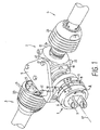
- Figur 1
- eine perspektivische Darstellung einer erfindungsgemäßen Drehmomentbegrenzungskupplung in einem Antrieb für ein landwirtschaftliches Gerät;
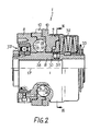
- Figur 2
- einen Teillängsschnitt der Drehmomentbegrenzungskupplung;
- Figur 3A
- eine schematische Ansicht der Drehmomentbegrenzungskupplung in Richtung der Längsachse, wobei die Schaltscheibe in der Drehmoment übertragenden Stellung und die Sperrklinke in Anlage zur Schaltfläche dargestellt ist;
- Figur 3B
- die Drehmomentbegrenzungskupplung gemäß Figur 3A, wobei die Schaltscheibe in ihrer Freilaufstellung und die Sperrklinke in Anlage zu einer ersten Sperrfläche der Kupplungsnabe dargestellt sind;
- Figur 3C
- die Drehmomentbegrenzungskupplung gemäß Figur 3A, wobei ein Sperransatz der Sperrklinke in eine Nut der Kupplungsnabe eingreift;
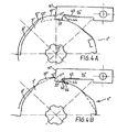
- Figur 4A
- eine Drehmomentbegrenzungskupplung gemäß Figur 3A, wobei die Sperrklinke ein Federelement aufweist, und
- Figur 4B
- eine Drehmomentbegrenzungskupplung gemäß Figur 3B, wobei das Federelement gegen eine zweite Sperrfläche der Kupplungsnabe abgestützt ist.
- 1
- Drehmomentbegrenzungskupplung
- 2
- Verteilergetriebe
- 3
- erste Gelenkwelle
- 4
- zweite Gelenkwelle
- 5
- Befestigungselement
- 6, 6', 6''
- Kupplungshülse
- 7
- Gelenkgabel
- 8, 8', 8''
- Kupplungsnabe
- 9, 9', 9''
- Schaltscheibe
- 10, 10', 10"
- Schaltnocken
- 11, 11', 11"
- Schaltfläche
- 12, 12'
- Sperrnocken
- 13, 13', 13''
- erste Sperrfläche
- 14, 14'
- Sperrklinke
- 15
- Betätigungselement
- 16, 16', 16''
- Anschlagfläche
- 17, 17', 17''
- Längsachse
- 18
- Flanschverbindung
- 19
- Gehäuse
- 20
- Bohrung
- 21
- Befestigungsschrauben
- 22
- Befestigungsmittel
- 23
- erste Gelenkgabel
- 24
- zweite Gelenkgabel
- 25
- Schutzvorrichtung
- 26
- Schutzvorrichtung
- 27
- Durchbruch
- 28
- Mitnehmerkörper
- 29
- erste Ausnehmung
- 30
- Drucklager
- 31
- Druckring
- 32
- Tellerfederpaket
- 33
- Stützring
- 34
- erste Laufrille
- 35
- zweite Laufrille
- 36
- zweite Ausnehmung
- 37
- Wälzlager
- 38
- Bohrung
- 39
- Sperransatz
- 40
- Außenumfangsfläche
- 41
- Sperrnut
- 42
- zweite Sperrflächen
- 43
- Federelement
- 44
- Schenkel
- 45
- Vertiefung
- 46
- zweite Sperrfläche
- A
- Antriebsdrehrichtung
Claims (3)
- Drehmomentbegrenzungskupplung insbesondere in einem Antriebsstrang zum Antreiben landwirtschaftlicher Geräte , umfassendeine Längsachse (17, 17', 17''), um die die Drehmomentbegrenzungskupplung (1) drehbar angeordnet ist,eine Kupplungsnabe (8, 8', 8"), die umfangsverteilte Durchbrüche (27) aufweist, in welchen Mitnehmerkörper (28) parallel zur Längsachse (17) verstellbar gehalten sind,eine die Kupplungsnabe (8, 8', 8'') in einer Antriebsdrehrichtung antreibende Kupplungshülse (6, 6', 6''), die zu den Durchbrüchen (27) korrespondierende erste Ausnehmungen (29) aufweist,eine Schaltscheibe (9, 9', 9''),die zwischen einer Drehmoment übertragenden Stellung und einer Freilaufstellung relativ zur Kupplungsnabe (8, 8', 8'') drehbar angeordnet ist,die durch in Umfangsrichtung wirkende Federmittel zur Drehmoment übertragenden Stellung beaufschlagt ist,die durch axial wirkende Federmittel (32) die Mitnehmerkörper (28) in Richtung zur Kupplungsnabe (8, 8', 8'') beaufschlagt, wobei die Mitnehmerkörper (28) zur Drehmomentübertragung in die Ausnehmungen der Kupplungshülse (6, 6', 6'') eingreifen,die bei Überschreiten eines vorgegebenen Nennmoments durch eine Abrollbewegung der Mitnehmerkörper (28) aus der Drehmoment übertragenden Stellung zur Freilaufstellung überführbar ist,die zu den Durchbrüchen (27) korrespondierende zweite Ausnehmungen (36) aufweist, in welche die Mitnehmerkörper (28) in der Freilaufstellung eingreifen,eine Sperrklinke (14, 14', 14''),dadurch gekennzeichnet, daß die Sperrklinke (14,14',14") Mittel (39) aufweist, die in der Sperrstellung der Sperrklinke (14', 14'') derart mit der Kupplungsnabe (8, 8') zusammenwirken, dass diese gegen Drehung entgegen der Antriebsdrehrichtung (A) gesperrt ist.die zwischen einer Freigabestellung und einer Sperrstellung bewegbar ist,die in der Sperrstellung mit einer radialen Schaltfläche (11, 11', 11'') auf dem Umfang der Schaltscheibe (9, 9', 9") derart zusammenwirkt, daß die Schaltscheibe (9, 9', 9'') von der Drehmoment übertragenden Stellung in die Freilaufstellung überführbar ist unddie in der Sperrstellung mit einer radial verlaufenden ersten Sperrfläche (13, 13', 13") der Kupplungsnabe (8, 8', 8'') derart zusammenwirkt, dass diese gegen Drehung um die Längsachse (17, 17', 17'') in der Antriebsdrehrichtung (A) gesperrt ist,
- Drehmomentbegrenzungskupplung nach Anspruch 1,
dadurch gekennzeichnet, dass in der Freilaufstellung der Schaltscheibe (9') die Sperrklinke (14') mit einem zur Längsachse (17') gerichteten Sperransatz (39) in eine radiale, die erste Sperrfläche (13') und eine zweite Sperrfläche (42) bildende Sperrnut (41) der Kupplungsnabe (8) eingreift und eine Drehung der Kupplungsnabe (8') in beide Drehrichtungen sperrt. - Drehmomentbegrenzungskupplung nach Anspruch 1,
dadurch gekennzeichnet, dass in der Freilaufstellung der Schaltscheibe (9'') die Sperrklinke (14'') einerseits mit einem radial in Richtung zur Drehmomentbegrenzungskupplung (1) gerichteten Sperransatz (39') gegen die erste Sperrfläche (13") der Kupplungsnabe (8") abgestützt ist und andererseits mit einem Federelement (43) gegen eine radiale zweite Sperrfläche (46) abgestützt ist.
Applications Claiming Priority (2)
| Application Number | Priority Date | Filing Date | Title |
|---|---|---|---|
| DE10145430A DE10145430C2 (de) | 2001-09-14 | 2001-09-14 | Drehmomentbegrenzungskupplung |
| DE10145430 | 2001-09-14 |
Publications (2)
| Publication Number | Publication Date |
|---|---|
| EP1293696A1 EP1293696A1 (de) | 2003-03-19 |
| EP1293696B1 true EP1293696B1 (de) | 2004-07-07 |
Family
ID=7699091
Family Applications (1)
| Application Number | Title | Priority Date | Filing Date |
|---|---|---|---|
| EP02016054A Expired - Lifetime EP1293696B1 (de) | 2001-09-14 | 2002-07-19 | Drehmomentbegrenzungskupplung |
Country Status (3)
| Country | Link |
|---|---|
| US (1) | US6749049B2 (de) |
| EP (1) | EP1293696B1 (de) |
| DE (1) | DE10145430C2 (de) |
Families Citing this family (6)
| Publication number | Priority date | Publication date | Assignee | Title |
|---|---|---|---|---|
| DE10201988C2 (de) | 2002-01-21 | 2003-12-24 | Walterscheid Gmbh Gkn | Drehmomentbegrenzungskupplung |
| DE10325221A1 (de) * | 2003-06-04 | 2004-12-23 | Zf Friedrichshafen Ag | Achse eines Fahrzeugs, insbesondere eines Nutzfahrzeugs |
| DE20318641U1 (de) | 2003-12-02 | 2005-04-21 | Trioliet Mullos B.V. | Sicherheitssystem für selbstladende Mischwagen |
| DE102009037026B4 (de) * | 2009-08-13 | 2011-07-28 | GKN Walterscheid GmbH, 53797 | Drehmomentbegrenzungskupplung |
| BE1024270B1 (nl) | 2016-10-06 | 2018-01-10 | Cnh Industrial Belgium Nv | Veiligheidskoppeling voor een landbouwvoertuig of gesleept toebehoren ervan |
| DE102019114200A1 (de) * | 2019-05-27 | 2020-12-03 | Schaeffler Technologies AG & Co. KG | Formschlusskupplung und Verfahren zum Koppeln einer Motorwelle mit einer Getriebeeingangswelle und/oder mit einer Zwischenwelle |
Family Cites Families (11)
| Publication number | Priority date | Publication date | Assignee | Title |
|---|---|---|---|---|
| US2644560A (en) * | 1947-08-20 | 1953-07-07 | Edward E Kleinschmidt | Latch operated clutch mechanism |
| GB1160062A (en) * | 1966-01-11 | 1969-07-30 | Fisholow Prod Ltd | Improvements in or relating to Overload Clutches |
| NL6606805A (de) * | 1966-05-18 | 1967-07-25 | ||
| IT1070120B (it) * | 1975-09-11 | 1985-03-25 | Walterscheid Gmbh Jean | Innesto a ruota libera per la limitazione della coppia trasmessa da un motore ad una macchina operatrice |
| DE3034606A1 (de) * | 1980-09-13 | 1982-03-25 | Jean Walterscheid Gmbh, 5204 Lohmar | Schaltvorrichtung fuer eine ueberlastkupplung |
| DE3151485C1 (de) * | 1981-12-24 | 1983-01-27 | Jean Walterscheid Gmbh, 5204 Lohmar | UEberlastkupplung |
| DE3344043A1 (de) * | 1983-12-06 | 1985-06-13 | Claas Saulgau GmbH, 7968 Saulgau | Schaltbare ueberlastkupplung |
| DE3438374C1 (de) * | 1984-10-19 | 1986-01-16 | Jean Walterscheid Gmbh, 5204 Lohmar | Überlastkupplung |
| DE3528591A1 (de) * | 1984-12-22 | 1986-07-10 | Jean Walterscheid Gmbh, 5204 Lohmar | In antriebseinrichtung abschaltbarer freilauf |
| DE3934963C1 (de) * | 1989-10-20 | 1991-02-28 | Jean Walterscheid Gmbh, 5204 Lohmar, De | |
| DE19611622C1 (de) * | 1996-03-25 | 1997-07-24 | Walterscheid Gmbh Gkn | Drehmomentbegrenzungskupplung |
-
2001
- 2001-09-14 DE DE10145430A patent/DE10145430C2/de not_active Expired - Lifetime
-
2002
- 2002-07-19 EP EP02016054A patent/EP1293696B1/de not_active Expired - Lifetime
- 2002-09-13 US US10/243,902 patent/US6749049B2/en not_active Expired - Lifetime
Also Published As
| Publication number | Publication date |
|---|---|
| EP1293696A1 (de) | 2003-03-19 |
| DE10145430A1 (de) | 2003-04-03 |
| DE10145430C2 (de) | 2003-09-25 |
| US20030054889A1 (en) | 2003-03-20 |
| US6749049B2 (en) | 2004-06-15 |
Similar Documents
| Publication | Publication Date | Title |
|---|---|---|
| EP0531321B1 (de) | Scheibenbremse für fahrzeuge | |
| EP2363317B1 (de) | Klemmrollenfreilauf für eine Verstellvorrichtung in einem Kraftfahrzeug | |
| DE10037808A1 (de) | Handwerkzeugmaschine | |
| DE2827948A1 (de) | Abschaltkupplung | |
| EP2136095B1 (de) | Kupplung zur Drehmomentbegrenzung | |
| EP0064763B1 (de) | Antrieb, insbesondere Verstellantrieb für Kraftfahrzeuge | |
| DE2729545C3 (de) | Drehmomentbegrenzungskupplung mit Freigang | |
| AT406985B (de) | Kupplung | |
| EP2284413B1 (de) | Drehmomentbegrenzungskupplung | |
| EP1293696B1 (de) | Drehmomentbegrenzungskupplung | |
| EP2045480B1 (de) | Drehmomentbegrenzungskupplung | |
| DE10201988C2 (de) | Drehmomentbegrenzungskupplung | |
| DE19829960C2 (de) | Drehmomentbegrenzungseinrichtung | |
| EP1576713B1 (de) | Adapter, getriebemotor und getriebemotor-baukasten | |
| EP2068027B1 (de) | Drehmomentbegrenzungskupplung | |
| EP1293693B1 (de) | Sicherheitskupplungsanordnung in einem Antrieb für Landmaschinen | |
| DE10348068A1 (de) | Kupplung zur Drehmomentbegrenzung | |
| DE19734467B4 (de) | Fliehkraftgesteuerter Schaltautomat | |
| EP2052900B1 (de) | Getriebeanordnung | |
| EP0009544B1 (de) | Überlastkupplung | |
| EP0870945A1 (de) | Kupplung zur Drehmomentbegrenzung | |
| DE3445564A1 (de) | Nachstellvorrichtung fuer eine scheibenbremse, insbesondere fuer kraftfahrzeuge | |
| EP1227209B1 (de) | Antriebseinrichtung für Tore | |
| DE4036911A1 (de) | Handwerkzeugmaschine mit bremskupplung | |
| EP4605661A1 (de) | Selbstrückstellendes sicherheitselement sowie kupplung umfassend mehrere dieser sicherheitselemente |
Legal Events
| Date | Code | Title | Description |
|---|---|---|---|
| PUAI | Public reference made under article 153(3) epc to a published international application that has entered the european phase |
Free format text: ORIGINAL CODE: 0009012 |
|
| AK | Designated contracting states |
Kind code of ref document: A1 Designated state(s): AT BE BG CH CY CZ DE DK EE ES FI FR GB GR IE IT LI LU MC NL PT SE SK TR |
|
| AX | Request for extension of the european patent |
Extension state: AL LT LV MK RO SI |
|
| 17P | Request for examination filed |
Effective date: 20030528 |
|
| AKX | Designation fees paid |
Designated state(s): DE FR GB IT NL |
|
| GRAP | Despatch of communication of intention to grant a patent |
Free format text: ORIGINAL CODE: EPIDOSNIGR1 |
|
| GRAS | Grant fee paid |
Free format text: ORIGINAL CODE: EPIDOSNIGR3 |
|
| GRAA | (expected) grant |
Free format text: ORIGINAL CODE: 0009210 |
|
| AK | Designated contracting states |
Kind code of ref document: B1 Designated state(s): DE FR GB IT NL |
|
| REG | Reference to a national code |
Ref country code: GB Ref legal event code: FG4D Free format text: NOT ENGLISH |
|
| GBT | Gb: translation of ep patent filed (gb section 77(6)(a)/1977) |
Effective date: 20040707 |
|
| RBV | Designated contracting states (corrected) |
Designated state(s): FR GB IT NL |
|
| REG | Reference to a national code |
Ref country code: IE Ref legal event code: FG4D Free format text: GERMAN |
|
| ET | Fr: translation filed | ||
| PLBE | No opposition filed within time limit |
Free format text: ORIGINAL CODE: 0009261 |
|
| STAA | Information on the status of an ep patent application or granted ep patent |
Free format text: STATUS: NO OPPOSITION FILED WITHIN TIME LIMIT |
|
| 26N | No opposition filed |
Effective date: 20050408 |
|
| REG | Reference to a national code |
Ref country code: DE Ref legal event code: 8566 |
|
| PGFP | Annual fee paid to national office [announced via postgrant information from national office to epo] |
Ref country code: GB Payment date: 20060721 Year of fee payment: 5 |
|
| GBPC | Gb: european patent ceased through non-payment of renewal fee |
Effective date: 20070719 |
|
| PG25 | Lapsed in a contracting state [announced via postgrant information from national office to epo] |
Ref country code: GB Free format text: LAPSE BECAUSE OF NON-PAYMENT OF DUE FEES Effective date: 20070719 |
|
| REG | Reference to a national code |
Ref country code: FR Ref legal event code: PLFP Year of fee payment: 15 |
|
| REG | Reference to a national code |
Ref country code: FR Ref legal event code: PLFP Year of fee payment: 16 |
|
| REG | Reference to a national code |
Ref country code: FR Ref legal event code: PLFP Year of fee payment: 17 |
|
| PGFP | Annual fee paid to national office [announced via postgrant information from national office to epo] |
Ref country code: NL Payment date: 20210721 Year of fee payment: 20 |
|
| PGFP | Annual fee paid to national office [announced via postgrant information from national office to epo] |
Ref country code: IT Payment date: 20210730 Year of fee payment: 20 Ref country code: FR Payment date: 20210722 Year of fee payment: 20 |
|
| REG | Reference to a national code |
Ref country code: NL Ref legal event code: MK Effective date: 20220718 |