EP1293733A2 - Radiator with a radiating plate and procedure for circulating a fluid inside of it - Google Patents
Radiator with a radiating plate and procedure for circulating a fluid inside of it Download PDFInfo
- Publication number
- EP1293733A2 EP1293733A2 EP02020161A EP02020161A EP1293733A2 EP 1293733 A2 EP1293733 A2 EP 1293733A2 EP 02020161 A EP02020161 A EP 02020161A EP 02020161 A EP02020161 A EP 02020161A EP 1293733 A2 EP1293733 A2 EP 1293733A2
- Authority
- EP
- European Patent Office
- Prior art keywords
- radiator
- plate
- previous
- pipe
- fittings
- Prior art date
- Legal status (The legal status is an assumption and is not a legal conclusion. Google has not performed a legal analysis and makes no representation as to the accuracy of the status listed.)
- Withdrawn
Links
- 239000012530 fluid Substances 0.000 title claims abstract description 27
- 238000000034 method Methods 0.000 title claims abstract description 13
- 238000010438 heat treatment Methods 0.000 claims abstract description 18
- 238000007599 discharging Methods 0.000 claims 1
- 239000000463 material Substances 0.000 description 1
- 239000002184 metal Substances 0.000 description 1
- 238000012986 modification Methods 0.000 description 1
- 230000004048 modification Effects 0.000 description 1
- 238000005192 partition Methods 0.000 description 1
Images

Classifications
-
- F—MECHANICAL ENGINEERING; LIGHTING; HEATING; WEAPONS; BLASTING
- F24—HEATING; RANGES; VENTILATING
- F24D—DOMESTIC- OR SPACE-HEATING SYSTEMS, e.g. CENTRAL HEATING SYSTEMS; DOMESTIC HOT-WATER SUPPLY SYSTEMS; ELEMENTS OR COMPONENTS THEREFOR
- F24D19/00—Details
- F24D19/0002—Means for connecting central heating radiators to circulation pipes
-
- F—MECHANICAL ENGINEERING; LIGHTING; HEATING; WEAPONS; BLASTING
- F24—HEATING; RANGES; VENTILATING
- F24D—DOMESTIC- OR SPACE-HEATING SYSTEMS, e.g. CENTRAL HEATING SYSTEMS; DOMESTIC HOT-WATER SUPPLY SYSTEMS; ELEMENTS OR COMPONENTS THEREFOR
- F24D19/00—Details
- F24D19/06—Casings, cover lids or ornamental panels, for radiators
-
- F—MECHANICAL ENGINEERING; LIGHTING; HEATING; WEAPONS; BLASTING
- F24—HEATING; RANGES; VENTILATING
- F24D—DOMESTIC- OR SPACE-HEATING SYSTEMS, e.g. CENTRAL HEATING SYSTEMS; DOMESTIC HOT-WATER SUPPLY SYSTEMS; ELEMENTS OR COMPONENTS THEREFOR
- F24D19/00—Details
- F24D19/06—Casings, cover lids or ornamental panels, for radiators
- F24D19/065—Grids attached to the radiator and covering its top
-
- F—MECHANICAL ENGINEERING; LIGHTING; HEATING; WEAPONS; BLASTING
- F24—HEATING; RANGES; VENTILATING
- F24D—DOMESTIC- OR SPACE-HEATING SYSTEMS, e.g. CENTRAL HEATING SYSTEMS; DOMESTIC HOT-WATER SUPPLY SYSTEMS; ELEMENTS OR COMPONENTS THEREFOR
- F24D19/00—Details
- F24D19/10—Arrangement or mounting of control or safety devices
- F24D19/1006—Arrangement or mounting of control or safety devices for water heating systems
- F24D19/1009—Arrangement or mounting of control or safety devices for water heating systems for central heating
- F24D19/1015—Arrangement or mounting of control or safety devices for water heating systems for central heating using a valve or valves
- F24D19/1018—Radiator valves
Definitions
- the present invention refers to a radiator with a radiating plate and to a procedure for circulating a fluid inside of it.
- radiators consisting of a single plate at the angles of which four fittings are usually connected through which a heating fluid is introduced or discharged into/from the radiator.
- the technical task proposed of the present invention is, therefore, that of eliminating the aforementioned technical drawbacks of the prior art, realising a radiator with a radiating plate and of indicating a procedure for heating it which allows the fittings for connection to the house-heating unit to be installed irrespective of the type and size of the radiator intended to be installed.
- a purpose of the invention is that of realising a radiator which is also particularly rigid and strong.
- the last but not least purpose of the invention is that of realising a radiator which is transportable without drawbacks of any sort.
- a radiator with a radiating plate, where the plate has at least one upper collector and at least one lower collector connected to each other through a plurality of channels, characterised in that said plate is divided into two parts defining at least one first and one second portion hydraulically connected through hydraulic connection means, said first portion having a supply fitting and said second portion having a discharge fitting for a heating fluid.
- the invention also refers to a procedure for circulating a fluid inside a radiator with radiating plates, characterised in that a heating fluid is entered into a substantially central zone of said plate divided into a first and second portion, it is initially made to circulate just in said first portion and then is transferred from said first portion to said second portion and is discharged from said second portion from a substantially central zone.
- a radiator with a radiating plate is shown, wholly indicated with reference numeral 1.
- the radiator 1 comprises a plate 2 which has two upper collectors 3 and two lower collectors 4 connected to each other by a plurality of channels 5 and hydraulically separated along a line 50 (for example welded, bent, realised through a partition, etc.) which divides the plate 2 into a first and second portion.
- a line 50 for example welded, bent, realised through a partition, etc.
- the plate 2 has, in particular, the first portion 6 and the second portion 7 connected through hydraulic connection means 8; the first portion 6 of the plate 2 has a supply fitting 9 for a heating fluid and the second portion has a discharge fitting 10 for the heating fluid.
- connection means 8 are outside the plate 2.
- the supply and discharge fittings 9, 10 for the heating fluid are connected to the plate 2 at a central and lower position thereof.
- the heating fluid cannot pass from the first portion 6 to the second portion 7 or vice-versa through the upper or lower collectors 3, 4, or through one of the channels 5, but just through the connection means 8 outside of the plate 2.
- the plate 2 has four fittings positioned in correspondence with the upper and lower corners and, in particular, has two T-shaped fittings 11, 12 in correspondence with the upper corners and two L-shaped fittings positioned in correspondence with the lower corners.
- connection means 8 comprise a pipe connected to each of the two portions of the plate.
- the pipe 8 has the first and second ends connected at 13, 14 to the fittings 11, 12 and is defined by a grid 15, for example made from folded sheet metal.
- the pipe 8 has the first end connected at 13 to the fitting 11 and the second end connected in correspondence with a central portion of the plate 2 substantially aligned with the discharge fitting 10.
- FIG 3 a further embodiment of the radiator is shown, in which the pipe 8 has a rectangular, rounded or squared section.
- the pipe 8 occupies a very small space and can be hidden, for example, in the grid.
- the pipe 8 is substantially positioned horizontally and in correspondence with the upper fittings of the plate.
- At least one of said fittings which connect to the pipe 8 comprises a special fitting 16.
- the special fitting 16 comprises a tubular body 17 inside of which two L-shaped protuberances 18 extend from two opposite portions of the body 17, which define a through-port 19
- the radiator allows the tubes of the home heating units to be laid in a very simple manner since the position of the supply and discharge fittings is always known irrespective of the type and size of the radiator.
- the procedure for circulating a fluid inside the radiator with a radiating plate according to the invention is substantially the following.
- the heating fluid enters from the supply fitting 9 into the plate and crosses the first portion 6 (as indicated by the arrows), it moves in correspondence with the fitting 13 and passes into the pipe 8.
- the procedure for circulating the fluid also consists of the fact that the heating fluid is entered into a central zone (through the fitting 9) of the plate 2 of the radiator, it flows towards a first side portion thereof (towards the fitting 11), it passes into a second side portion (through the fitting 12) of the radiator through a pipe outside of the plate and again flows towards the centre of the radiator (fitting 10) from where it is discharged.
- the fluid circulates from the bottom to the top of the plate whereas in the second it circulates from the top to the bottom.
- the radiator with a radiating plate and the procedure for circulating a fluid inside it according to the invention are particularly advantageous because the pipe occupies a very small space and can even be hidden by the grid.
- the pipe makes the radiator particularly rigid and strong, reducing its problems of transportation and fitting.
- the radiator with a radiating plate and the procedure for circulating a fluid inside of it thus conceived are susceptible to numerous modifications and variants, all of which are covered by the inventive concept; moreover, all of the details can be replaced by technically equivalent elements.
Landscapes
- Engineering & Computer Science (AREA)
- Physics & Mathematics (AREA)
- Thermal Sciences (AREA)
- Chemical & Material Sciences (AREA)
- Combustion & Propulsion (AREA)
- Mechanical Engineering (AREA)
- General Engineering & Computer Science (AREA)
- Steam Or Hot-Water Central Heating Systems (AREA)
- Drying Of Solid Materials (AREA)
- Domestic Hot-Water Supply Systems And Details Of Heating Systems (AREA)
Abstract
The radiator (1) with a radiating plate (2), where the plate
(2) has at least one upper collector (3) and at least one lower
collector (4) connected to each other through a plurality of
channels (5). The plate (2) is divided into two parts defining
at least one first and one second portion (6, 7) connected
through hydraulic connection means (8). The first portion (6)
has a supply fitting (9) and said second portion (7) has a
discharge fitting (10) for a heating fluid. In the procedure for
circulating a fluid inside the radiator with radiating plates a
heating fluid is entered into a substantially central zone of
the plate divided into a first and second portion, it is
initially made to circulate just in the first portion and then
is transferred from the first portion to the second portion and
is discharged from the second portion from a substantially
central zone.
Description
- The present invention refers to a radiator with a radiating plate and to a procedure for circulating a fluid inside of it.
- In particular, hereafter reference shall be made to radiators consisting of a single plate at the angles of which four fittings are usually connected through which a heating fluid is introduced or discharged into/from the radiator.
- Conventional radiators of the type indicated, however, have numerous drawbacks mainly due to the fact that, since the supply and discharge fittings are arranged in correspondence with the corners of the plate, the installer must position the connection fittings of the house-heating unit in different positions according to the type of radiator intended to be installed and its size.
- Moreover, such types of radiator are not very resistant to stress with all the consequences which can come from this, for example in transportation.
- The technical task proposed of the present invention is, therefore, that of eliminating the aforementioned technical drawbacks of the prior art, realising a radiator with a radiating plate and of indicating a procedure for heating it which allows the fittings for connection to the house-heating unit to be installed irrespective of the type and size of the radiator intended to be installed.
- In this technical task a purpose of the invention is that of realising a radiator which is also particularly rigid and strong.
- The last but not least purpose of the invention is that of realising a radiator which is transportable without drawbacks of any sort.
- The technical task, as well as these and other purposes, according to the present invention, are achieved by realising a radiator with a radiating plate, where the plate has at least one upper collector and at least one lower collector connected to each other through a plurality of channels, characterised in that said plate is divided into two parts defining at least one first and one second portion hydraulically connected through hydraulic connection means, said first portion having a supply fitting and said second portion having a discharge fitting for a heating fluid.
- The invention also refers to a procedure for circulating a fluid inside a radiator with radiating plates, characterised in that a heating fluid is entered into a substantially central zone of said plate divided into a first and second portion, it is initially made to circulate just in said first portion and then is transferred from said first portion to said second portion and is discharged from said second portion from a substantially central zone.
- Other characteristics of the present invention are defined, moreover, in the subsequent claims.
- Further characteristics and advantages of the invention shall become clearer from the description of a preferred but not exclusive embodiment of the radiator with radiating plate and of the procedure for circulating a fluid inside of it according to the finding, where the radiator is illustrated for indicating and not limiting purposes in the attached drawings, in which:
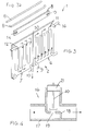
- figure 1 shows a partially exploded schematic perspective view of a first embodiment of the radiator;
- figure 2 shows a partially exploded schematic perspective view of a second embodiment of the radiator;
- figure 3 shows a partially exploded schematic perspective view of a third embodiment of the radiator;
- figure 3a shows a schematic perspective view of two different embodiments of radiator pipes according to the finding; and
- figure 4 shows a cross section of a special fitting of the radiator according to the finding.
- With reference to the quoted figures, a radiator with a radiating plate is shown, wholly indicated with
reference numeral 1. - The
radiator 1 comprises aplate 2 which has two upper collectors 3 and twolower collectors 4 connected to each other by a plurality ofchannels 5 and hydraulically separated along a line 50 (for example welded, bent, realised through a partition, etc.) which divides theplate 2 into a first and second portion. - The
plate 2 has, in particular, thefirst portion 6 and thesecond portion 7 connected through hydraulic connection means 8; thefirst portion 6 of theplate 2 has a supply fitting 9 for a heating fluid and the second portion has a discharge fitting 10 for the heating fluid. - Advantageously, the connection means 8 are outside the
plate 2. - Preferably, the supply and
discharge fittings plate 2 at a central and lower position thereof. - The heating fluid cannot pass from the
first portion 6 to thesecond portion 7 or vice-versa through the upper orlower collectors 3, 4, or through one of thechannels 5, but just through the connection means 8 outside of theplate 2. - The
plate 2 has four fittings positioned in correspondence with the upper and lower corners and, in particular, has two T-shaped fittings - The connection means 8 comprise a pipe connected to each of the two portions of the plate.
- In a first embodiment, shown in figure 1, the
pipe 8 has the first and second ends connected at 13, 14 to thefittings - In a second example, shown in figure 2, the
pipe 8 has the first end connected at 13 to thefitting 11 and the second end connected in correspondence with a central portion of theplate 2 substantially aligned with the discharge fitting 10. - In figure 3 a further embodiment of the radiator is shown, in which the
pipe 8 has a rectangular, rounded or squared section. - In this way the
pipe 8 occupies a very small space and can be hidden, for example, in the grid. - Preferably, the
pipe 8 is substantially positioned horizontally and in correspondence with the upper fittings of the plate. - In a preferred embodiment, at least one of said fittings which connect to the
pipe 8 comprises aspecial fitting 16. - In particular, in figure 4 a section of the
special fitting 16 is shown. - The
special fitting 16 comprises atubular body 17 inside of which two L-shaped protuberances 18 extend from two opposite portions of thebody 17, which define a through-port 19 - A
shutter 20 of a modulatingvalve 21, connected to a seat of thebody 17 and capable of being actuated automatically by a thermostatic head or else by an operator to close theport 19 manually, can be associated with saidport 19. - The radiator allows the tubes of the home heating units to be laid in a very simple manner since the position of the supply and discharge fittings is always known irrespective of the type and size of the radiator.
- The procedure for circulating a fluid inside the radiator with a radiating plate according to the invention is substantially the following.
- The heating fluid enters from the supply fitting 9 into the plate and crosses the first portion 6 (as indicated by the arrows), it moves in correspondence with the
fitting 13 and passes into thepipe 8. - From the
pipe 8 it passes into thesecond portion 7 of theplate 2, it crosses it and comes out from thesecond portion 7 of the plate through the discharge fitting 10. - The procedure for circulating the fluid also consists of the fact that the heating fluid is entered into a central zone (through the fitting 9) of the
plate 2 of the radiator, it flows towards a first side portion thereof (towards the fitting 11), it passes into a second side portion (through the fitting 12) of the radiator through a pipe outside of the plate and again flows towards the centre of the radiator (fitting 10) from where it is discharged. - In the first portion the fluid circulates from the bottom to the top of the plate whereas in the second it circulates from the top to the bottom.
- In practice, it has been noted how the radiator with a radiating plate and the procedure for circulating a fluid inside it according to the invention are particularly advantageous because the pipe occupies a very small space and can even be hidden by the grid.
- Moreover, the pipe makes the radiator particularly rigid and strong, reducing its problems of transportation and fitting.
- The radiator with a radiating plate and the procedure for circulating a fluid inside of it thus conceived are susceptible to numerous modifications and variants, all of which are covered by the inventive concept; moreover, all of the details can be replaced by technically equivalent elements.
- In practice, the materials used, as well as the sizes, can be whatever according to the requirements and the state of the art.
Claims (16)
- Radiator (1) with a radiating plate (2), where the plate (2) has at least one upper collector (3) and at least one lower collector (4) connected to each other through a plurality of channels (5), characterised in that said plate (2) is divided into two parts defining at least one first and one second portion (6, 7) hydraulically connected through hydraulic connection means (8), said first portion (6) having a supply fitting (9) and said second portion (7) having a discharge fitting (10) for a heating fluid.
- Radiator (1) according to claim 1, characterised in that said hydraulic connection means (8) are outside of said plate (2).
- Radiator (1) according to one or more of the previous claims, characterised in that said fittings (9, 10) for supplying and discharging the heating fluid are arranged in a substantially central position of said plate (2).
- Radiator (1) according to one or more of the previous claims, characterised in that said first and second portion (6, 7) are substantially the same as each other and said supply and discharge fittings are arranged below said plate.
- Radiator (1) according to one or more of the previous claims, characterised in that said plate (2) has at least two fittings (11, 12) positioned in correspondence with its upper and/or lower corners.
- Radiator (1) according to one or more of the previous claims, characterised in that said connection means (8) comprise at least one pipe connected to each of said portions (6, 7) of said plate (2).
- Radiator (1) according to one or more of the previous claims, characterised in that said pipe (8) has a first end connected to at least one of said upper fittings (11, 12) of said plate (2).
- Radiator (1) according to one or more of the previous claims, characterised in that a second end of said pipe (8) is connected at a substantially central zone of said plate (2).
- Radiator (1) according to one or more of the previous claims, characterised in that said pipe (8) has a rectangular, rounded or squared section.
- Radiator (1) according to one or more of the previous claims, characterised in that said pipe (8) is defined by a grid (15) covering said plate (2).
- Radiator (1) according to one or more of the previous claims, characterised in that said upper fittings (11, 12) are T-shaped.
- Radiator (1) according to one or more of the previous claims, characterised in that at least one of said upper fittings (11, 12) which connect to said pipe (8) comprises a special fitting (16).
- Radiator (1) according to one or more of the previous claims, characterised in that said special fitting (16) has a modulating valve (21) associated with it.
- Procedure for circulating a fluid inside a radiator with radiating plates, characterised in that a heating fluid is entered into a substantially central zone of said plate divided into a first and second portion, it is initially made to circulate just in said first portion and then is transferred from said first portion to said second portion and is discharged from said second portion from a substantially central zone.
- Procedure according to the previous claim, characterised in that in said first portion said fluid circulates substantially from the bottom to the top and in said second portion it circulates substantially from the top to the bottom.
- Radiator with a radiating plate and procedure for circulating a fluid inside of it, as described and claimed.
Applications Claiming Priority (2)
| Application Number | Priority Date | Filing Date | Title |
|---|---|---|---|
| ITMI20011903 | 2001-09-12 | ||
| IT2001MI001903A ITMI20011903A1 (en) | 2001-09-12 | 2001-09-12 | RADIANT PLATE RADIATOR AND PROCEDURE FOR THE CIRCULATION OF UNFLUID INSIDE IT |
Publications (1)
| Publication Number | Publication Date |
|---|---|
| EP1293733A2 true EP1293733A2 (en) | 2003-03-19 |
Family
ID=11448359
Family Applications (1)
| Application Number | Title | Priority Date | Filing Date |
|---|---|---|---|
| EP02020161A Withdrawn EP1293733A2 (en) | 2001-09-12 | 2002-09-09 | Radiator with a radiating plate and procedure for circulating a fluid inside of it |
Country Status (3)
| Country | Link |
|---|---|
| EP (1) | EP1293733A2 (en) |
| IT (1) | ITMI20011903A1 (en) |
| NO (1) | NO20024342L (en) |
Cited By (2)
| Publication number | Priority date | Publication date | Assignee | Title |
|---|---|---|---|---|
| GB2393779A (en) * | 2002-09-18 | 2004-04-07 | Tms Turker Makina Sanayi Ve Ti | Central heating radiator |
| WO2008088232A1 (en) * | 2007-01-20 | 2008-07-24 | Formaster S.A. | Heater, especially for central heating |
-
2001
- 2001-09-12 IT IT2001MI001903A patent/ITMI20011903A1/en unknown
-
2002
- 2002-09-09 EP EP02020161A patent/EP1293733A2/en not_active Withdrawn
- 2002-09-11 NO NO20024342A patent/NO20024342L/en not_active Application Discontinuation
Cited By (2)
| Publication number | Priority date | Publication date | Assignee | Title |
|---|---|---|---|---|
| GB2393779A (en) * | 2002-09-18 | 2004-04-07 | Tms Turker Makina Sanayi Ve Ti | Central heating radiator |
| WO2008088232A1 (en) * | 2007-01-20 | 2008-07-24 | Formaster S.A. | Heater, especially for central heating |
Also Published As
| Publication number | Publication date |
|---|---|
| ITMI20011903A0 (en) | 2001-09-12 |
| ITMI20011903A1 (en) | 2003-03-12 |
| NO20024342L (en) | 2003-03-13 |
| NO20024342D0 (en) | 2002-09-11 |
Similar Documents
| Publication | Publication Date | Title |
|---|---|---|
| US5400853A (en) | Modular heating/cooling coil design and coil flow connector | |
| US5950575A (en) | Hydronic manifold | |
| KR100596161B1 (en) | Separate Double Heat Exchanger Hot Water Boiler | |
| DK3098553T3 (en) | Plate heat exchanger system | |
| US4917077A (en) | Wall-mounted hot water boiler of the instant type | |
| WO1988006260A1 (en) | Convector/radiator construction | |
| US4564142A (en) | Hydronic system with circulators connected to a header | |
| US2229266A (en) | Heat exchanger | |
| EP1028298B1 (en) | Heating apparatus having an one-piece cast heat exchanger | |
| GB2302727A (en) | Spiral heat exchange coil for fluid containment vessels | |
| RU2455580C2 (en) | Radiator with partial load function | |
| US4510891A (en) | Liquid boiler, particularly utility-water boiler | |
| DE4224212A1 (en) | Double-walled combustion chamber for water heater - has lamellar tubes, surrounded on opposite sides by top sections of double jacket | |
| US2068236A (en) | Radiator | |
| US3366092A (en) | Heating boiler | |
| GB2120377A (en) | A panel radiator | |
| EP0595945A1 (en) | Double-walled heating section. | |
| EP1371908A1 (en) | Water heater with high performance heat exchanger | |
| ITMI20011903A1 (en) | RADIANT PLATE RADIATOR AND PROCEDURE FOR THE CIRCULATION OF UNFLUID INSIDE IT | |
| KR102638189B1 (en) | Heat supply apparatus | |
| US1936235A (en) | Radiator | |
| GB2306215A (en) | Directing flow within a radiator | |
| US4177766A (en) | Heat recovery system for furnaces and the like | |
| US1973388A (en) | Radiator structure | |
| EP0976989B1 (en) | Water circuit of a combined service wall-mounted gas-fired boiler |
Legal Events
| Date | Code | Title | Description |
|---|---|---|---|
| PUAI | Public reference made under article 153(3) epc to a published international application that has entered the european phase |
Free format text: ORIGINAL CODE: 0009012 |
|
| AK | Designated contracting states |
Kind code of ref document: A2 Designated state(s): AT BE BG CH CY CZ DE DK EE ES FI FR GB GR IE IT LI LU MC NL PT SE SK TR Designated state(s): AT BE BG CH CY CZ DE DK EE ES FI FR GB GR IE IT LI LU MC NL PT SE SK TR |
|
| AX | Request for extension of the european patent |
Extension state: AL LT LV MK RO SI |
|
| STAA | Information on the status of an ep patent application or granted ep patent |
Free format text: STATUS: THE APPLICATION HAS BEEN WITHDRAWN |
|
| 18W | Application withdrawn |
Effective date: 20030704 |