EP1294111A2 - Dispositif optique, système et méthode de détection d'une condition dans un dispositif optique - Google Patents
Dispositif optique, système et méthode de détection d'une condition dans un dispositif optique Download PDFInfo
- Publication number
- EP1294111A2 EP1294111A2 EP02256437A EP02256437A EP1294111A2 EP 1294111 A2 EP1294111 A2 EP 1294111A2 EP 02256437 A EP02256437 A EP 02256437A EP 02256437 A EP02256437 A EP 02256437A EP 1294111 A2 EP1294111 A2 EP 1294111A2
- Authority
- EP
- European Patent Office
- Prior art keywords
- loop
- optical
- signal
- attenuator
- detected
- Prior art date
- Legal status (The legal status is an assumption and is not a legal conclusion. Google has not performed a legal analysis and makes no representation as to the accuracy of the status listed.)
- Granted
Links
- 230000003287 optical effect Effects 0.000 title claims abstract description 111
- 238000000034 method Methods 0.000 title claims abstract description 12
- 230000005540 biological transmission Effects 0.000 claims abstract description 29
- 230000004044 response Effects 0.000 claims abstract description 20
- 238000012544 monitoring process Methods 0.000 claims abstract description 8
- 230000006854 communication Effects 0.000 claims description 10
- 238000004891 communication Methods 0.000 claims description 10
- 230000002238 attenuated effect Effects 0.000 claims description 2
- 230000008878 coupling Effects 0.000 claims 2
- 238000010168 coupling process Methods 0.000 claims 2
- 238000005859 coupling reaction Methods 0.000 claims 2
- 230000008054 signal transmission Effects 0.000 claims 2
- 239000000835 fiber Substances 0.000 description 18
- 238000001069 Raman spectroscopy Methods 0.000 description 5
- 238000010586 diagram Methods 0.000 description 4
- 239000013307 optical fiber Substances 0.000 description 3
- 229910052761 rare earth metal Inorganic materials 0.000 description 3
- 150000002910 rare earth metals Chemical class 0.000 description 3
- 229910052691 Erbium Inorganic materials 0.000 description 2
- 238000010521 absorption reaction Methods 0.000 description 2
- 238000004458 analytical method Methods 0.000 description 2
- 230000007175 bidirectional communication Effects 0.000 description 2
- 238000006243 chemical reaction Methods 0.000 description 2
- 238000001514 detection method Methods 0.000 description 2
- UYAHIZSMUZPPFV-UHFFFAOYSA-N erbium Chemical compound [Er] UYAHIZSMUZPPFV-UHFFFAOYSA-N 0.000 description 2
- 238000005086 pumping Methods 0.000 description 2
- 230000003321 amplification Effects 0.000 description 1
- 238000005452 bending Methods 0.000 description 1
- 230000015556 catabolic process Effects 0.000 description 1
- 230000008859 change Effects 0.000 description 1
- 238000012937 correction Methods 0.000 description 1
- 230000001186 cumulative effect Effects 0.000 description 1
- 230000007812 deficiency Effects 0.000 description 1
- 238000006731 degradation reaction Methods 0.000 description 1
- 239000006185 dispersion Substances 0.000 description 1
- 230000009977 dual effect Effects 0.000 description 1
- 230000007257 malfunction Effects 0.000 description 1
- 238000005259 measurement Methods 0.000 description 1
- 238000003199 nucleic acid amplification method Methods 0.000 description 1
- 230000008569 process Effects 0.000 description 1
- 230000008439 repair process Effects 0.000 description 1
- 230000011664 signaling Effects 0.000 description 1
- 230000002269 spontaneous effect Effects 0.000 description 1
- 238000013024 troubleshooting Methods 0.000 description 1
- 238000011144 upstream manufacturing Methods 0.000 description 1
- 230000035899 viability Effects 0.000 description 1
- XLYOFNOQVPJJNP-UHFFFAOYSA-N water Substances O XLYOFNOQVPJJNP-UHFFFAOYSA-N 0.000 description 1
Images

Classifications
-
- H—ELECTRICITY
- H04—ELECTRIC COMMUNICATION TECHNIQUE
- H04B—TRANSMISSION
- H04B10/00—Transmission systems employing electromagnetic waves other than radio-waves, e.g. infrared, visible or ultraviolet light, or employing corpuscular radiation, e.g. quantum communication
- H04B10/03—Arrangements for fault recovery
- H04B10/035—Arrangements for fault recovery using loopbacks
-
- H—ELECTRICITY
- H04—ELECTRIC COMMUNICATION TECHNIQUE
- H04B—TRANSMISSION
- H04B10/00—Transmission systems employing electromagnetic waves other than radio-waves, e.g. infrared, visible or ultraviolet light, or employing corpuscular radiation, e.g. quantum communication
- H04B10/07—Arrangements for monitoring or testing transmission systems; Arrangements for fault measurement of transmission systems
- H04B10/071—Arrangements for monitoring or testing transmission systems; Arrangements for fault measurement of transmission systems using a reflected signal, e.g. using optical time domain reflectometers [OTDR]
Definitions
- This invention relates in general to optical communication systems, and in particular to a system and method for detecting a condition in an optical device.
- Optical communication systems in particular long-haul networks of lengths longer than 600 kilometers, inevitably suffer from signal attenuation due to a variety of factors including scattering, absorption, and bending.
- repeaters are typically placed at regular intervals along the optical transmission path. Each repeater boosts the input optical signal to compensate for accumulated transmission losses.
- this function was accomplished solely by regenerators, which convert optical signals into electrical form and then back to optical form in order to amplify, reshape, retime, and re-transmit the optical signal.
- regenerators which convert optical signals into electrical form and then back to optical form in order to amplify, reshape, retime, and re-transmit the optical signal.
- the advent of reliable and low cost optical amplifiers has largely obviated the need to make such optical-electrical-optical conversions, although longer spans may still require such conversions depending on the amount of signal degradation.
- Optical amplifiers include rare earth doped fibers such as erbium doped fiber amplifiers (EDFAs) and Raman amplifiers.
- EDFAs erbium doped fiber amplifiers
- Raman amplifiers An EDFA operates by passing an optical signal through an erbium-doped fiber segment, and "pumping" the segment with light from another source such as a laser.
- the pumping energy may be provided at 1480 nm or 980 nm for an EDFA, which corresponds with the absorption peaks of erbium.
- Raman amplification occurs throughout an optical transmission fiber when the transmission fiber is pumped at an appropriate wavelength or wavelengths. Gain is then achieved at a longer wavelength through the process of Stimulated Raman Scattering.
- optical communication systems may employ a line monitoring system (LMS).
- the line monitoring system may include line-monitoring equipment (LME) located in the terminal stations and loop-back paths in the repeaters and terminals.
- LME line-monitoring equipment
- the loop-back paths optically couple two fibers of a fiber pair (one in each direction of transmission) such that a portion of the optical signal originating at a transmitting terminal and being transmitted on one of the fibers of the pair is looped back and coupled into the fiber that is transmitting in the reverse direction back toward the transmitting terminal.
- the fundamental quantity measured by the LME is the round-trip loop gain between the LME and each terminal and repeater loop-back path on a fiber pair.
- the difference between the baseline loop gain levels and the measured loop gain levels is typically referred to as the loop-back signature.
- measured loop gains may be determined for each of the amplifier pairs in the sequence in which the amplifier pairs are encountered along the transmission path. That is, a first data point would represent the loop gain from the LME to the first amplifier pair, and a second data point would represent the gain from the LME to the second amplifier pair, and so on.
- the difference between the baseline curve and the measured curve is a representation of the loop-back signature.
- An ideal signature is a straight horizontal line running through a gain change of 0 dB, indicating that all the loop gain measurements from the amplifier pairs agree exactly with the pre-established baseline. In practice, however, system noise and other transmission variations will normally occur. As a result, a nominal signature will typically have a random shape within some pre-established window about the zero line defining a nominal band of acceptability. Extreme faults, such as fiber breaks and other problems that result in immediate loss of service, will typically result in a signature shape with one or more points of the signature outside of the pre-established window. However, there is a class of other faults and conditions, which typically would not be expected to result in any discemable differences that could be detected by the LME. For instance, the failure of a redundant electrical power supply or a rise in temperature beyond the expected limits in an area housing the optical device in a terrestrial system would not otherwise be detected by the LME until it resulted in some equipment fault.
- An optical device consistent with the invention includes first and second transmission paths, and a loop-back path.
- the loop-back path couples a portion of an optical signal from the first transmission path to the second transmission path as a loop-back signal, and includes at least one optical attenuator configured to attenuate the loop-back signal in response to at least one detected condition.
- the loop-back signal may be detected by the LME where the attenuation imparted by the attenuator is interpreted as an indication of one or more detected conditions in a class of conditions associated with the attenuator setting.
- a method of monitoring an optical device consistent with the present invention includes detecting a condition in the optical device, attenuating a loop-back signal on a loop-back path in said device in response to the detected condition, and detecting the attenuated loop-back signal.
- FIG. 1 there is illustrated an exemplary optical communication system 100 consistent with the present invention.
- system 100 has been depicted in a highly simplified form for ease of explanation. It is to be understood that the present invention is not limited to illustrated exemplary embodiments described herein. In fact, the present invention may be incorporated into a wide variety of optical networks, systems and devices without departing from the spirit and scope of the invention.
- the optical communication system 100 includes transmitter/receiver terminals 32, 34 connected via an optical information channel 106 supporting bi-directional communication.
- the terminal 32 is generally described and illustrated in FIG. 1 as a transmitting terminal and the terminal 34 is illustrated and generally described as a receiving terminal.
- both terminals 32, 34 may serve as transmitting and receiving terminals and, as such, each includes both transmitters and receivers and associated multiplexers and demultiplexers.
- the optical information channel 106 may include optical fiber paths 20, 40, optical amplifiers 22, 42, regenerators, optical filters, dispersion compensating modules, and other active and passive components. A variety of configurations for each of these elements will be known to those skilled in the art.
- the transmitting terminal 32 includes optical transmitters 200, 214, ... 216 for transmitting optical communication channels at associated wavelengths, e.g., ⁇ 1 , ⁇ 2 , ... ⁇ n .
- Multiplexer 210 combines these signals into an aggregate signal that is launched into a first optical fiber path 20 for transmission to the receiving terminal 34.
- demultiplexer 212 demultiplexes the aggregate signal and routes the channel wavelengths, e.g., ⁇ 1 , ⁇ 2 , ... ⁇ n , to receivers 208, 218 ... 220, respectively.
- the terminal 34 may also include a multiplexer 222 for combining signals into an aggregate signal that is launched into a second optical fiber path 40 for transmission to the demultiplexer 220 in the transmitter/receiver terminal 32.
- Optical amplifiers may include Raman amplifiers, rare earth doped amplifiers such as an EDFA, or the like. Pairs of optical amplifiers supporting opposite-traveling signals on separate fiber pairs may typically be housed in a single repeater unit 30.
- the repeaters may be spaced by a number of kilometers, e.g., 50 kilometers or more, depending on system characteristics and requirements.
- the repeaters may be under water in long-haul submarine applications or in a switching station or the like in terrestrial applications. While only three optical amplifier pairs are illustrated in FIG. 1 for clarity of discussion, those skilled in the art will recognize that any number of optical amplifier pairs may be utilized in varying transmission path lengths.
- a loop-back path 26 couples a portion of the optical signal from the first transmission path 20 to the second transmission path 40 to provide a loop-back signal for detection by LME 230.
- the LME may be located in the first transmitter/receiver terminal 32 and connected to both a demultiplexer 220 that receives signals from the second optical transmission path 40 and multiplexer 210 that transmits signals to the first optical transmission path 20.
- another LME (not shown) may be located in the other transmitter/receiver 34.
- each repeater in the transmission system may include such a loop-back path.
- each loop-back path may establish a path in both loop-back directions.
- the loop-back path 26 may also couple a portion of the optical signal from the second transmission path 40 to the first transmission path 20.
- an optical attenuator 104 is coupled to the loop-back path 26 of the repeater 30.
- a controller 102 is provided for controlling the attenuation level of the attenuator 104 in response to an output from a detector 103 configured to detect a fault or condition. When the condition is present, the controller sets an associated predetermined attenuation level for the attenuator. The predetermined attenuation is detected and interpreted by the LME 230 as corresponding to the detected condition.
- the detector 103 may be configured to detect a variety of faults or conditions.
- the detector 103 may be a temperature sensor.
- the detector may provide an output to the controller for causing an associated predetermined attenuation level for the attenuator.
- the attenuation imparted to the loop-back signal in the loop-back path 26 may be detected at the LME 230 to indicate a high temperature condition at the repeater. Knowledge of the high temperature condition may allow correction of the condition prior to repeater failure.
- the detector 103 may be configured to detect an external DC bus failure.
- electrical power to repeaters in terrestrial applications is supplied in dual feeds for added reliability. If one feed malfunctions, the other feed supplies the necessary power.
- the detector 103 may sense the failure and cause the controller to set the attenuator to a predetermined attenuation level associated with the bus failure.
- the attenuation-level may be detected at the LME to indicate a bus failure condition at the repeater, enabling repair prior to failure of the alternate feed.
- faults or conditions that may be detected such as, but not limited to, internal optical amplifier faults and electrical/optical internal faults.
- faults or conditions may be divided into associated fault categories. Each fault category may trigger the optical attenuator to attenuate to a predetermined attenuation level associated therewith.
- faults including an internal optical amplifier fault, and an internal electrical/optical fault may be categorized as "internal" faults.
- Other faults including an external DC bus failure and others may be categorized as "external” faults.
- the optical attenuator 104 may then be controlled by the controller 102 to attenuate to a first predetermined level for an "internal" fault, and to a second predetermined level for an "external” fault. In this way, certain internal faults will trigger a first predetermined attenuation level that may be detected by the LME 230, and certain external faults will trigger a second predetermined attenuation level that may also be detected by the LME.
- the type and quantity of faults to be divided in each fault category may be specified by a particular customer need and may be stored in a non-volatile memory device local to the particular optical device.
- the maximum and minimum chosen level of attenuation depends on the optical communication system characteristics including the span length, number of repeaters, number of channels, etc. In one example, the maximum level of attenuation is 15 dB because any more attenuation would lead to an undetectable loop-back signal.
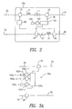
- the repeater 30a includes a pair of optical amplifiers.
- the optical amplifiers shown and described in reference to FIG. 2 are rare earth doped fiber amplifiers such as EDFAs.
- other optical amplifiers such as Raman amplifiers may be utilized in an optical device consistent with the present invention.
- a pump source 60 is coupled to the first transmission path 20 by coupler 25 for generating gain in a doped fiber section 21.
- the pump source 60 may also be coupled to the second transmission path 40.
- pump wavelengths 980 nm or 1480 nm are suitable.
- the pump source 60 may include one or a plurality of pumps provided in a wide variety of configurations. A number of pump sources are known to those skilled in the art, including, for example, laser pump sources.
- a variety of couplers 25 for combining the pump energy into each fiber path are also known, e.g., optical couplers or a wavelength division multiplexer.
- An optical isolator 27 may also be located immediately downstream from each of the doped fibers.
- the isolator 27 acts as an amplified spontaneous emission (ASE) filter to prevent ASE from traveling back upstream and disrupting system stability. Such ASE typically causes optical amplifiers to oscillate.
- ASE amplified spontaneous emission
- another coupler 29 is provided for separating a portion of the total power in the transmitted signal, i.e., a loop-back signal, onto a loop-back path 26.
- the loop-back path couples a portion of the optical signal transmitted on path 20 to transmission path 40, or vice-versa, for analysis by the LME 230.
- the LME may monitor the loop gain, i.e., the cumulative gain on the path through path 20, the loop-back path, and path 40 and back to the LME 230 to ascertain the viability of the elements in the loop.
- active and passive components e.g., various filters such as Fiber Bragg Gratings, that may be utilized in the exemplary repeater 30a without departing from the scope of the present invention.
- an optical attenuator 104 is coupled to the loop-back path 26 for attenuating the loop-back signal to one or more predetermined levels in response to associated faults or conditions.
- detector 103 detects a fault condition and causes the controller to set the predetermined attenuation level at the attenuator in response to the condition.
- the predetermined attenuation level applied to the loop-back signal may be detected and interpreted by the LME 230 as corresponding to the detected fault condition.
- an exemplary loop-back path 26a may include a plurality of redundant detector and controller pairs 103a-1 and 102a-1, 103a-2 and 102a-2, ... 103a-n and 102a-n coupled to a single variable optical attenuator 104a.
- groups of the redundant detector and controller pairs may be configured to detect similar fault conditions. In one embodiment, only one fault detector and controller pair is operational, at any one given time, to control the optical attenuator 104a.
- a plurality of redundant detector and controller pairs may be used with a corresponding number of associated optical attenuators 104b-1, 104b-2, ... 104b-n.
- This configuration may utilize only one detector and controller pair with one optical attenuator at a time 103b-1, 102b-1, 104b-1 and use the others as backup.
- this configuration may utilize each detector 103b-1, 103b-2, ... 103b-n to detect an associated condition, e.g., temperature, external bus voltage, etc.
- Each associated controller 102b-1, 102b-2, ... 102b-n may then be responsive to the detected fault conditions to trigger an associated attenuation level in its associated optical attenuator 104b-1, 104b-2, ... 104b-n.
- the optical attenuators in any of the aforementioned embodiments may be variable or fixed attenuators.
- a variable attenuator may be capable of imparting attenuation in a variety of different attenuation ranges, e.g., over a range of 1.0 dB to 35 dB, while a fixed attenuator attenuates a signal to only a fixed attenuation level.
- the fixed attenuation level may also be in the 1.0 dB to 35 dB range.
- the chosen attenuation level should be great enough such that the resulting loop-back gain signature at the LME is clearly distinguishable from random signature fluctuations about the pre-determined signature band.
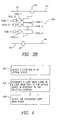
- a condition in an optical device e.g., a repeater including a pair of optical amplifiers
- Conditions may include any number of faults or fault conditions as detailed earlier.
- a predetermined attenuation is imparted 404 to a loop-back signal in a loop-back path of the device to facilitate detection 406 of the condition, e.g., by the LME.
- This enables more targeted and efficient troubleshooting to take place in an optical communication system.
- each optical attenuator may be a fixed or variable attenuator depending on system requirements.
Landscapes
- Physics & Mathematics (AREA)
- Electromagnetism (AREA)
- Engineering & Computer Science (AREA)
- Computer Networks & Wireless Communication (AREA)
- Signal Processing (AREA)
- Optical Communication System (AREA)
Applications Claiming Priority (2)
| Application Number | Priority Date | Filing Date | Title |
|---|---|---|---|
| US953754 | 2001-09-17 | ||
| US09/953,754 US6714715B2 (en) | 2001-09-17 | 2001-09-17 | Optical device, system and method for detecting a condition in an optical device |
Publications (3)
| Publication Number | Publication Date |
|---|---|
| EP1294111A2 true EP1294111A2 (fr) | 2003-03-19 |
| EP1294111A3 EP1294111A3 (fr) | 2003-11-19 |
| EP1294111B1 EP1294111B1 (fr) | 2008-01-09 |
Family
ID=25494490
Family Applications (1)
| Application Number | Title | Priority Date | Filing Date |
|---|---|---|---|
| EP02256437A Expired - Lifetime EP1294111B1 (fr) | 2001-09-17 | 2002-09-17 | Dispositif optique, système et méthode de détection d'une condition dans un dispositif optique |
Country Status (4)
| Country | Link |
|---|---|
| US (1) | US6714715B2 (fr) |
| EP (1) | EP1294111B1 (fr) |
| CA (1) | CA2403492C (fr) |
| DE (1) | DE60224484T2 (fr) |
Cited By (2)
| Publication number | Priority date | Publication date | Assignee | Title |
|---|---|---|---|---|
| US20120155857A1 (en) * | 2009-08-27 | 2012-06-21 | Huawei Marine Networks Co., Ltd. | Method, apparatus and unit for detecting fault of submarine device |
| WO2013078017A1 (fr) * | 2011-11-23 | 2013-05-30 | Tyco Electronics Subsea Communications Llc | Système et procédé utilisant l'injection de fautes dans des lignes de base d'un système de surveillance de lignes |
Families Citing this family (5)
| Publication number | Priority date | Publication date | Assignee | Title |
|---|---|---|---|---|
| US7206516B2 (en) * | 2002-04-30 | 2007-04-17 | Pivotal Decisions Llc | Apparatus and method for measuring the dispersion of a fiber span |
| US20060189276A1 (en) * | 2004-12-08 | 2006-08-24 | Michael Halinski | Methods and systems for intelligent adaptive gain control |
| US8462324B2 (en) | 2010-11-11 | 2013-06-11 | Corning Cable Systems Llc | Monitoring fibers in an optical ribbon cable |
| EP3264635B1 (fr) | 2014-02-05 | 2019-12-04 | Aurrion, Inc. | Architecture d'émetteur-récepteur photonique ayant une fonctionnalité de bouclage |
| DE102018010305C5 (de) * | 2018-09-10 | 2026-02-19 | Inova Semiconductors Gmbh | Segmentierte Steuerungsanordnung |
Family Cites Families (16)
| Publication number | Priority date | Publication date | Assignee | Title |
|---|---|---|---|---|
| JPH03129310A (ja) | 1989-10-14 | 1991-06-03 | Canon Inc | 距離検出光学系 |
| JP2649737B2 (ja) | 1990-07-05 | 1997-09-03 | 国際電信電話株式会社 | 光増幅器の励起光源駆動方式 |
| US5825515A (en) | 1991-09-03 | 1998-10-20 | Lucent Technologies Inc. | Supervisory apparatus for optical transmission system |
| JP2846212B2 (ja) | 1993-04-21 | 1999-01-13 | 国際電信電話株式会社 | 監視信号受信方法及び装置 |
| JP2994531B2 (ja) | 1993-07-06 | 1999-12-27 | ケイディディ株式会社 | 光波長分散測定方法及び装置 |
| US5535039A (en) * | 1994-12-08 | 1996-07-09 | Harris Corporation | Divergence feedback in a linear fiber optic analog transmission system and method |
| JP3611631B2 (ja) | 1995-03-20 | 2005-01-19 | Kddi株式会社 | 線路監視方法および線路監視装置 |
| JPH109961A (ja) | 1996-06-21 | 1998-01-16 | Kokusai Denshin Denwa Co Ltd <Kdd> | 光波長監視装置 |
| US6175436B1 (en) * | 1996-07-30 | 2001-01-16 | Tellium, Inc. | Automatic feedback gain control for multiple channels in a doped optical fiber amplifier |
| JP3402083B2 (ja) | 1996-08-05 | 2003-04-28 | Kddi株式会社 | 光ファイバ線路の障害位置検出装置 |
| JP3346233B2 (ja) | 1997-08-18 | 2002-11-18 | ケイディーディーアイ株式会社 | 光伝送線路監視装置 |
| JP3588984B2 (ja) | 1997-08-20 | 2004-11-17 | Kddi株式会社 | 光パワー計測システム並びにそのための端局及び中継器 |
| US6041070A (en) * | 1997-11-14 | 2000-03-21 | Sdl, Inc. | Resonant pumped short cavity fiber laser |
| JP2000312185A (ja) * | 1999-04-28 | 2000-11-07 | Nec Corp | 波長多重光伝送用光中継増幅器およびこれを用いた波長多重光伝送装置 |
| JP2000324053A (ja) * | 1999-05-07 | 2000-11-24 | Nec Corp | 分岐装置 |
| KR100350482B1 (ko) * | 1999-07-22 | 2002-08-28 | 삼성전자 주식회사 | 비동기전송모드 무선접속망의 고장관리방법 |
-
2001
- 2001-09-17 US US09/953,754 patent/US6714715B2/en not_active Expired - Lifetime
-
2002
- 2002-09-16 CA CA2403492A patent/CA2403492C/fr not_active Expired - Fee Related
- 2002-09-17 EP EP02256437A patent/EP1294111B1/fr not_active Expired - Lifetime
- 2002-09-17 DE DE60224484T patent/DE60224484T2/de not_active Expired - Lifetime
Cited By (5)
| Publication number | Priority date | Publication date | Assignee | Title |
|---|---|---|---|---|
| US20120155857A1 (en) * | 2009-08-27 | 2012-06-21 | Huawei Marine Networks Co., Ltd. | Method, apparatus and unit for detecting fault of submarine device |
| EP2472745A4 (fr) * | 2009-08-27 | 2013-07-31 | Huawei Marine Networks Co Ltd | Méthode, appareil et dispositif de détection de défaillances de dispositifs immergés |
| US9059797B2 (en) * | 2009-08-27 | 2015-06-16 | Huawei Marine Networks Co., Ltd. | Method, apparatus and unit for detecting fault of submarine device |
| WO2013078017A1 (fr) * | 2011-11-23 | 2013-05-30 | Tyco Electronics Subsea Communications Llc | Système et procédé utilisant l'injection de fautes dans des lignes de base d'un système de surveillance de lignes |
| US9749041B2 (en) | 2011-11-23 | 2017-08-29 | Tyco Electronics Subsea Communications Llc | System and method using fault injection into line monitoring system baselines |
Also Published As
| Publication number | Publication date |
|---|---|
| US20030052253A1 (en) | 2003-03-20 |
| US6714715B2 (en) | 2004-03-30 |
| DE60224484D1 (de) | 2008-02-21 |
| DE60224484T2 (de) | 2009-01-08 |
| CA2403492C (fr) | 2012-03-13 |
| CA2403492A1 (fr) | 2003-03-17 |
| EP1294111B1 (fr) | 2008-01-09 |
| EP1294111A3 (fr) | 2003-11-19 |
Similar Documents
| Publication | Publication Date | Title |
|---|---|---|
| US6683712B2 (en) | Optical amplification apparatus using Raman amplification | |
| US8135274B2 (en) | System and method for fault identification in optical communication systems | |
| US6064501A (en) | Method of determining optical amplifier failures | |
| US20040196158A1 (en) | Optical amplifier provided with control function of pumping light, and optical transmission system using the same | |
| US6490387B2 (en) | Optical transmission device and optical transmission system employing the same | |
| US20120033293A1 (en) | Method and apparatus of detecting an opening in an optical transmission fiber of a ropa system | |
| US7957643B2 (en) | Method and apparatus for automatically controlling optical signal power in optical transmission systems | |
| US6147796A (en) | Method for determining transmission parameters for the data channels of a WDM optical communication system | |
| US20070258132A1 (en) | Improved feedback dynamic gain control for a wdm system employing multi wavelength pumped raman fiber amplifiers | |
| US6714715B2 (en) | Optical device, system and method for detecting a condition in an optical device | |
| US6404527B1 (en) | Method and apparatus for transmitting a response signal from an optical repeater to a terminal requesting status information | |
| US10142026B2 (en) | Raman pumping arrangement with improved OSC sensitivity | |
| CN1934807B (zh) | 光通信网络及其组成部件 | |
| US20050036790A1 (en) | Method and system for optical fiber transmission using Raman amplification | |
| JP4798939B2 (ja) | 光増幅器のポンプを制御するためのシステムおよび方法 | |
| CN117375724A (zh) | 一种水下设备以及通信系统 | |
| US20070253718A1 (en) | Optical Add/Drop Amplification Device | |
| JP4225035B2 (ja) | 光増幅中継伝送システムとその監視制御方法 | |
| JPH09116502A (ja) | 監視用ループバック回路を有する高出力光増幅中継器 | |
| JP3774566B2 (ja) | 光伝送装置およびそれを利用した光伝送システム | |
| EP1868030B1 (fr) | Appareil d'amplification optique utilisant une amplification raman | |
| JPH0437227A (ja) | 光伝送網及びその監視方法 |
Legal Events
| Date | Code | Title | Description |
|---|---|---|---|
| PUAI | Public reference made under article 153(3) epc to a published international application that has entered the european phase |
Free format text: ORIGINAL CODE: 0009012 |
|
| 17P | Request for examination filed |
Effective date: 20021016 |
|
| AK | Designated contracting states |
Kind code of ref document: A2 Designated state(s): AT BE BG CH CY CZ DE DK EE ES FI FR GB GR IE IT LI LU MC NL PT SE SK TR |
|
| AX | Request for extension of the european patent |
Extension state: AL LT LV MK RO SI |
|
| PUAL | Search report despatched |
Free format text: ORIGINAL CODE: 0009013 |
|
| AK | Designated contracting states |
Kind code of ref document: A3 Designated state(s): AT BE BG CH CY CZ DE DK EE ES FI FR GB GR IE IT LI LU MC NL PT SE SK TR |
|
| AX | Request for extension of the european patent |
Extension state: AL LT LV MK RO SI |
|
| AKX | Designation fees paid |
Designated state(s): DE FR GB |
|
| 17Q | First examination report despatched |
Effective date: 20070103 |
|
| GRAP | Despatch of communication of intention to grant a patent |
Free format text: ORIGINAL CODE: EPIDOSNIGR1 |
|
| GRAS | Grant fee paid |
Free format text: ORIGINAL CODE: EPIDOSNIGR3 |
|
| GRAA | (expected) grant |
Free format text: ORIGINAL CODE: 0009210 |
|
| AK | Designated contracting states |
Kind code of ref document: B1 Designated state(s): DE FR GB |
|
| REG | Reference to a national code |
Ref country code: GB Ref legal event code: FG4D |
|
| REF | Corresponds to: |
Ref document number: 60224484 Country of ref document: DE Date of ref document: 20080221 Kind code of ref document: P |
|
| ET | Fr: translation filed | ||
| PLBE | No opposition filed within time limit |
Free format text: ORIGINAL CODE: 0009261 |
|
| STAA | Information on the status of an ep patent application or granted ep patent |
Free format text: STATUS: NO OPPOSITION FILED WITHIN TIME LIMIT |
|
| 26N | No opposition filed |
Effective date: 20081010 |
|
| PGFP | Annual fee paid to national office [announced via postgrant information from national office to epo] |
Ref country code: GB Payment date: 20120925 Year of fee payment: 11 |
|
| PGFP | Annual fee paid to national office [announced via postgrant information from national office to epo] |
Ref country code: FR Payment date: 20121001 Year of fee payment: 11 |
|
| PGFP | Annual fee paid to national office [announced via postgrant information from national office to epo] |
Ref country code: DE Payment date: 20120927 Year of fee payment: 11 |
|
| REG | Reference to a national code |
Ref country code: DE Ref legal event code: R119 Ref document number: 60224484 Country of ref document: DE |
|
| GBPC | Gb: european patent ceased through non-payment of renewal fee |
Effective date: 20130917 |
|
| REG | Reference to a national code |
Ref country code: DE Ref legal event code: R079 Ref document number: 60224484 Country of ref document: DE Free format text: PREVIOUS MAIN CLASS: H04B0010080000 Ipc: H04B0010070000 |
|
| REG | Reference to a national code |
Ref country code: FR Ref legal event code: ST Effective date: 20140530 |
|
| REG | Reference to a national code |
Ref country code: DE Ref legal event code: R079 Ref document number: 60224484 Country of ref document: DE Free format text: PREVIOUS MAIN CLASS: H04B0010080000 Ipc: H04B0010070000 Effective date: 20140610 Ref country code: DE Ref legal event code: R119 Ref document number: 60224484 Country of ref document: DE Effective date: 20140401 |
|
| PG25 | Lapsed in a contracting state [announced via postgrant information from national office to epo] |
Ref country code: GB Free format text: LAPSE BECAUSE OF NON-PAYMENT OF DUE FEES Effective date: 20130917 |
|
| PG25 | Lapsed in a contracting state [announced via postgrant information from national office to epo] |
Ref country code: DE Free format text: LAPSE BECAUSE OF NON-PAYMENT OF DUE FEES Effective date: 20140401 Ref country code: FR Free format text: LAPSE BECAUSE OF NON-PAYMENT OF DUE FEES Effective date: 20130930 |