EP1294177A2 - Bildverarbeitungsverfahren und -vorrichtung - Google Patents
Bildverarbeitungsverfahren und -vorrichtung Download PDFInfo
- Publication number
- EP1294177A2 EP1294177A2 EP02256227A EP02256227A EP1294177A2 EP 1294177 A2 EP1294177 A2 EP 1294177A2 EP 02256227 A EP02256227 A EP 02256227A EP 02256227 A EP02256227 A EP 02256227A EP 1294177 A2 EP1294177 A2 EP 1294177A2
- Authority
- EP
- European Patent Office
- Prior art keywords
- image
- tuning
- color
- images
- conversion
- Prior art date
- Legal status (The legal status is an assumption and is not a legal conclusion. Google has not performed a legal analysis and makes no representation as to the accuracy of the status listed.)
- Granted
Links
Images


Classifications
-
- H—ELECTRICITY
- H04—ELECTRIC COMMUNICATION TECHNIQUE
- H04N—PICTORIAL COMMUNICATION, e.g. TELEVISION
- H04N1/00—Scanning, transmission or reproduction of documents or the like, e.g. facsimile transmission; Details thereof
- H04N1/46—Colour picture communication systems
- H04N1/56—Processing of colour picture signals
- H04N1/60—Colour correction or control
- H04N1/6011—Colour correction or control with simulation on a subsidiary picture reproducer
-
- H—ELECTRICITY
- H04—ELECTRIC COMMUNICATION TECHNIQUE
- H04N—PICTORIAL COMMUNICATION, e.g. TELEVISION
- H04N1/00—Scanning, transmission or reproduction of documents or the like, e.g. facsimile transmission; Details thereof
- H04N1/46—Colour picture communication systems
- H04N1/56—Processing of colour picture signals
- H04N1/60—Colour correction or control
- H04N1/603—Colour correction or control controlled by characteristics of the picture signal generator or the picture reproducer
- H04N1/6052—Matching two or more picture signal generators or two or more picture reproducers
- H04N1/6055—Matching two or more picture signal generators or two or more picture reproducers using test pattern analysis
Definitions
- the present invention relates to an image processing method and apparatus and, for example, to a color reproduction process of a printer.
- a method of making color correction for improving a color reproduction effect in a color reproduction process of a printer or printing press a method of converting data on an input color space into data on an output color space by a color masking method of obtaining data on an output color space by making matrix operations of data on an input color space is prevalently used.
- the output characteristics of a color printer or printing press exhibit strong nonlinearity. Therefore, in a global method such as the color masking method, i.e., a color correction method in which a change in element of a matrix influences the overall output color space, the characteristics of a color printer or printing press cannot be satisfactorily approximated in the entire color gamut.
- the present invention has been proposed to address the conventional problems, and has as its object to provide a profile which can accurately approximate strong nonlinear output characteristics of a color printer or printing press, and allows accurate color reproduction.
- An image processing method of the present invention comprises the following steps.
- an image processing method for generating a first conversion condition used to convert a device-independent color signal into a device-dependent color signal, and a second conversion condition used to convert the device-dependent color signal into another device-independent color signal, on the basis of colorimetric values of color patches output from an output device, comprising the steps of: inputting first and second image signals which depend on a target device, and converting the first and second image signals using a third conversion condition for the target device, which is used to convert a color signal depending on the target device into a device-independent color signal; displaying first and second preview images, which are respectively represented by image signals obtained by converting the converted first and second image signals using the first conversion condition, and further converting the first and second image signals using the second conversion condition; and displaying first and second original images, which are respectively represented by the first and second image signals obtained by conversion using the third conversion condition, wherein the first and second preview images and the first and second original images are displayed as different windows.
- the method further comprises the steps of: selecting an arbitrary color range to be tuned; setting a tuning parameter for the selected color range; and tuning the first and second conversion conditions on the basis of the tuning parameter.
- Fig. 1 is a block diagram showing an example of an image processing apparatus of the first embodiment.
- a signal input to the image processing apparatus shown in Fig. 1 is an image signal of a color space depending on an arbitrary device and, for example, can be an RGB signal which represents an image scanned from a document by an arbitrary scanner, or a CMYK signal to be output to an arbitrary printer.
- an input signal is an RGB signal that represents an image scanned by a scanner.
- the input signal is a CMYK signal to be output to a printing press as a target.
- Such input signal is input to an input color ⁇ Lab converter 101, and is converted into a signal on an Lab color space as a device-independent color space. This conversion is implemented by LUT conversion using an input color ⁇ Lab conversion LUT 102.
- a table corresponding to the color space of the input signal must be set. For example, when an image signal depending on an RGB color space of scanner A is input, a three-dimensional input - three-dimensional output RGB ⁇ Lab conversion table which represents correspondence between RGB values that depend on the RGB color space of scanner A, and Lab values, is set as a table of the input color ⁇ Lab conversion LUT 102.
- CMYK ⁇ Lab conversion table which represents correspondence between CMYK values that depend on the color space of printer B, and Lab values, is set as a table of the input color ⁇ Lab conversion LUT 102.
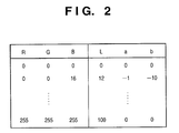
- Fig. 2 shows an example of an RGB ⁇ Lab conversion table, and shows correspondence between 8-bit RGB and Lab values. Since an actual table stores Lab values using typical RGB values as addresses, the input color ⁇ Lab converter 101 extracts an Lab value near the input RGB value from the table, and makes an interpolation operation for the extracted Lab value to acquire an Lab value corresponding to the input RGB value.
- An Lab signal output from the input color ⁇ Lab converter 101 is converted into a signal of a device RGB color space by an Lab ⁇ device RGB converter 104 on the basis of a device RGB ⁇ Lab conversion LUT 105. Details of this conversion process will be described later.
- the color space of the input signal is an RGB color space
- its color gamut is often broader than the color reproduction range of a printer.
- the Lab signal output from the input color ⁇ Lab converter 101 is mapped on the color reproduction range of a printer 107 by a color space compression converter 103 (gamut mapping), and is then input to the Lab ⁇ device RGB converter 104.
- gamut mapping a method of executing a color space compression process in a uniform color space, as disclosed in Japanese Patent Laid-Open No. 8-130655, or the like may be used. Also, other known color space compression methods may be used.
- a signal of the device RGB color space output from the Lab ⁇ device RGB converter 104 is converted into a signal of a CMYK color space, which depends on the printer 107, by a device RGB ⁇ CMYK converter 106, and the converted signal is sent to the printer 107.
- CMYK complementary metal-oxide-semiconductor
- Various methods are available for RGB ⁇ CMYK conversion, and an arbitrary method may be used. For example, conversion formulas (1) below are used.
- the Lab ⁇ device RGB converter 104 converts a signal on the basis of correspondence between device RGB values and Lab colorimetric values, which is obtained in advance.
- Fig. 3 is a flow chart showing the sequence for executing Lab ⁇ device RGB conversion by obtaining correspondence between device RGB values ⁇ Lab colorimetric values. Of course, if the correspondence between device RGB values ⁇ Lab colorimetric values has already been obtained, steps S1 and S2 are skipped.
- a color patch generator 108 generates sample images formed by a plurality of color patches, as shown in Fig. 4.
- the RGB signals of the generated sample images are output to the printer 107 via the device RGB ⁇ CMYK converter 106 to obtain sample images 109.
- the color patch generator 108 generates sample images by equally dividing the device RGB color space.
- the RGB color space in which R, G, and B data are respectively expressed by 8 bits is equally divided into 9 ⁇ 9 ⁇ 9 to obtain 729 patches.
- a color space depending on the printer 107 is a CMYK color space, but since the RGB color space can be converted into the CMYK color space via a conversion rule, the RGB color space is considered as a color space depending on the printer 107.
- a color patch colorimetry unit 110 measures the color patches of the obtained sample image 109 to obtain Lab colorimetric values of the respective color patches.
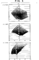
- the obtained Lab colorimetric values are distributed on an Lab color space, as shown in Fig. 5.
- the RGB values generated by the color patch generator 108 and Lab colorimetric values measured by the color patch colorimetry unit 110 can be obtained and, hence, a table of the device RGB ⁇ Lab conversion LUT 105 can be obtained.
- RGB ⁇ Lab conversion LUT 105 Lab ⁇ device RGB conversion is done.
- an interpolation operation such as cubic interpolation, tetrahedral interpolation, or the like as a known method is used.
- Such interpolation operation requires grids at equal intervals, which correspond to the input side of an LUT.
- the table of the device RGB ⁇ Lab conversion LUT 105 device RGB values are arranged at equal intervals, but Lab colorimetric values are not arranged at equal intervals. For this reason, when Lab values are to be input, the table of the device RGB ⁇ Lab conversion LUT 105 does not form an LUT having grids at equal intervals. Hence, an interpolation operation that inputs Lab values cannot be simply made. Hence, Lab ⁇ device RGB conversion is made in the following sequence.
- Distances d (equivalent to a color difference based on the Lab color difference method) between Lab values included in the table of the device RGB ⁇ Lab conversion LUT 105 and input Lab values are calculated and are stored in a memory.
- N entries ( ⁇ ) are selected in ascending order of distance d with respect to the input Lab values (o ⁇ ). At this time, entries are described as follows in ascending order of distance d.
- the number N of sample points used in the interpolation operation can be defined by a constant (e.g., 8) in the entire Lab color space.
- a constant e.g. 8
- L* low lightness
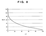
- a problem may be posed if N is a constant. That is, in a region where colorimetric values are concentrated, distance d becomes very small, and if N is small, the interpolation operation is made by multiplying a few sample points by large weighting coefficients.
- problems such as tone jump in the device RGB color space, collapse of white balance in a low-lightness region, and the like readily occur.
- the Lab signal can be converted into the device RGB signal.
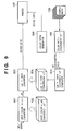
- Fig. 9 is a block diagram showing an example of the arrangement of an image processing apparatus of the second embodiment. Unlike in the image processing apparatus of the first embodiment, the image processing apparatus of the second embodiment converts a signal of a device-independent color space into a signal of a color space of the printer 107 using an LUT as in conversion of an input signal into a signal of a device-independent color space.
- An Lab ⁇ CMYK converter 803 converts an Lab signal into a signal of a CMYK color space depending on the printer 107 using an Lab ⁇ CMYK conversion LUT 804.
- a CMYK signal output from the Lab ⁇ CMYK converter 803 is sent to the printer 107.
- the Lab ⁇ CMYK conversion LUT 804 is generated as follows.
- CMYK signals of sample images generated by a color patch generator 808 are output to the printer 107 to obtain sample images 109.
- the color patch colorimetry unit 110 measures color patches of the obtained sample images 109 to obtain Lab colorimetric values of the color patches. Based on the obtained Lab colorimetric values and CMYK values generated by the color patch generator 808, an Lab ⁇ CMYK conversion LUT generator 810 generates a CMYK ⁇ Lab conversion LUT. Based on the generated CMYK ⁇ Lab conversion LUT, the Lab ⁇ CMYK conversion LUT 804 is generated using the same method as in the first embodiment.
- an Lab value is an 8-bit signal
- an L* value ranges from 0 to 255
- a* and b* values range from -128 to 127.
- the Lab color space is converted into the device RGB color space using the LUT, and the device RGB color space is then converted into the CMYK color space by the arithmetic process.
- these conversion processes can be done using a single LUT, thus improving the conversion efficiency.
- Fig. 10 is a block diagram showing an example of the arrangement of an image processing apparatus of the third embodiment, and this apparatus has an arrangement for receiving an input signal of an sRGB color space which will become a standard color space in the Internet.
- the sRGB color space can be considered as a device-independent color space.
- the printer 107 can reproduce an image expressed by a signal on the sRGB color space.
- an sRGB ⁇ CMYK converter 901 converts an input signal of the sRGB color space into a signal of the CMYK color space which depends on the printer 107 using an sRGB ⁇ CMYK conversion LUT 902.
- a CMYK signal output from the sRGB ⁇ CMYK converter 901 is sent to the printer 107.
- the sRGB ⁇ CMYK conversion LUT 902 is generated as follows.
- RGB signals of sample images generated by the color patch generator 108 are converted into CMYK signals depending on the printer 107 by the device RGB ⁇ CMYK converter 106, and the CMYK signals are output to the printer 107, thus obtaining sample images 109.
- the color patch colorimetry unit 110 measures color patches of the obtained sample images 109 to obtain Lab colorimetric values of the color patches. Based on the obtained Lab colorimetric values and the RGB values generated by the color patch generator 108, an sRGB ⁇ CMYK conversion LUT generator 908 generates a table of the sRGB ⁇ CMYK conversion LUT 902.
- the process of the sRGB ⁇ CMYK conversion LUT generator 908 generates a table of the sRGB ⁇ CMYK conversion LUT 902 on the basis of CMYK values obtained by executing the device RGB ⁇ CMYK conversion process described in the first embodiment for the RGB values generated by the color patch generator 108, and sRGB values obtained by executing Lab ⁇ XYZ and XYZ ⁇ sRGB conversion processes according to definition formulas for the Lab colorimetric values.
- an sRGB signal is an 8-bit signal
- 17 ⁇ 17 ⁇ 17 sRGB grids are formed by dividing the respective ranges of sRGB by 16 steps
- a color conversion method which can accurately approximate the strong nonlinear output characteristics of a color printer or printing press, and can achieve accurate color reproduction can be provided. Therefore, since color space conversion that satisfactorily reflects the characteristics of a printer or printing press is done in a device-independent color space, the printer or printing press can achieve accurate color reproduction for every input color spaces.
- the Lab color space has been explained as a device-independent color space.
- another uniform color space e.g., an Luv color space is used, the same effects can be obtained.
- the device value (e.g., CMYK) ⁇ Lab conversion LUT described in the above embodiment correspond to a destination profile (BtoA0) 1101D of an output device shown in Fig. 12, and the Lab ⁇ device value (e.g., CMYK) conversion LUT corresponds to a source profile (AtoB0) 1101S of an output device shown in Fig. 12
- an image that has undergone color conversion in correspondence with the output characteristics of a printing press as a target is printed using a copying machine or printer for the purpose of proof (test print, proof for correction).
- proof print proof for correction
- sample image data must be supplied to an output device used in proof to make the device print sample images, and profiles must be generated based on the colorimetric values of color patches of the obtained sample images by the method explained in each of the above embodiments. Then, an image that has undergone color conversion using the generated profiles is printed by the output device.
- the fourth embodiment is characterized in that the processing result based on the profiles of an output device used in proof, which are generated by the method described in each of the above embodiments, is confirmed, and the profiles can be tuned as needed.
- the profiles to be tuned are not limited to those for proof but can be used in a normal output process (print process).
- Fig. 11 is a block diagram showing an example of the arrangement of a color conversion module.
- a colorimeter (spectrophotometer) 1001 and colorimetry module 1002 measure color patches of sample images (e.g., standard IT8 or 4320CMYK images).
- the colorimetry result is supplied to a profile generation module 1003 on-line or off-line, thus generating a profile 1101D (Lab ⁇ CMYK conversion LUT: BtoA0) and profile 1101S (device value ⁇ Lab conversion LUT: AtoB0) as output device profiles, which comply with the ICC (International Color Consortium) definitions, by the method described in each of the above embodiments.
- a preview module 1005 supplies (or designates) an image 1006 to be proofed, a control chart 1007, a profile (target device value ⁇ Lab conversion LUT) 1102 corresponding to a target device, the profiles 1101D and 1101S of an output device, and a monitor profile 1103 to a color management module (CMM) 1108, and makes the CMM 1108 execute color conversion of the image 1006 and control chart 1007.
- CMM color management module
- a profile tuning module 1009 tunes the output device profiles 1101D and 1101S generated by the profile generation module 1003 on the basis of a user's instruction.
- Profile generation in the fourth embodiment uses the same method as in each of the above embodiments, but is characterized by allowing the user to tune the profiles. Functions in the fourth embodiment, which can improve user's usability, will be described in detail below.
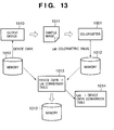
- Fig. 13 is a chart for explaining a target profile generation sequence, i.e., a chart for explaining the process described in the second embodiment more briefly.
- Device CMYK data of a sample image which is selected by the user from a memory 1012, is supplied to an output device 1010 to make it print a sample image 1011.
- the sample image uses, e.g., standard IT8 or 4320CMYK images.
- the colorimeter 1001 and colorimetry module 1002 measure color patches of the sample image 1011 printed by the output device 1010, and store Lab colorimetric values in the memory 1012.
- the profile generation module 1003 generates a device CMYK ⁇ Lab conversion table 1013 corresponding to an AtoB0 tag of an ICC profile, and stores it in the memory 1012.
- the profile generation module 1003 since a BtoA0 tag is required in addition to the AtoB0 tag, the profile generation module 1003 generates an Lab ⁇ device CMYK conversion table 1014 on the basis of the device CMYK ⁇ Lab conversion table 1013. These conversion tables are finally stored in the memory 1012 as the ICC profiles of the output device 1010.
- Device CMYK values in the device CMYK ⁇ Lab conversion table 1013 are arranged at equal intervals, but Lab colorimetric values are not arranged at equal intervals.
- Lab values Upon generating the Lab ⁇ device CMYK conversion table 1014 that receives Lab values as inputs, Lab values must be arranged at equal intervals.
- the Lab ⁇ device CMYK conversion table 1014 in which Lab values are arranged at equal intervals is generated based on the device CMYK ⁇ Lab conversion table 1013 using the method described in the first embodiment, and is stored in the memory 1012.
- a preview function of making monitor display for the purpose of confirming if the generated target profile is appropriate will be described below.
- the preview function is launched after the profiles are generated by the aforementioned process.
- Fig. 12 shows the color conversion sequence executed by the CMM 1008 shown in Fig. 11.
- CMYK data of an image 1006 is converted into Lab data using the AtoB0 tag of the target device profile 1102, and the Lab data is converted into CMYK data of the CMYK color space that depends on the output device 1010 using the BtoA0 tag (destination profile 1101D) of the output device profile 1101.
- this CMYK data is sent to an output device for proof.
- the CMYK data of the CMYK color space which depends on the target, is converted into Lab data again using the AtoB0 tag (source profile 1101S) of the output device profile 1101.
- the Lab data is converted into RGB data of a color space, which depends on a monitor 1004, using the monitor profile 1103, and the RGB data is displayed on the monitor 1004. That is, an image which will be printed by the target, i.e., a preview image B1, can be displayed on the monitor 1004, and its color reproducibility can be observed.
- the Lab data that has been converted using the target device profile 1102 is directly converted into RGB data using the monitor profile 1103, and the RGB data is displayed as an original image A1 on the monitor 1004, the preview image B1 which has undergone color conversion using the output device profile 1101 and the original image A1 (an image that the target device will output) which does not undergo any conversion can be observed and compared on the monitor 1004. Therefore, whether or not the generated output device profile 1101 is appropriate can be confirmed by observing and comparing the two images.
- CMYK data of the control chart 1007 a preview chart B2 and original chart A2 are displayed on the monitor 1004 in the same sequence as the image 1006.
- Fig. 14 shows a basic example of a preview window displayed on the monitor 1004 and, for example, the original image A1 and preview image B1 are respectively displayed on the upper left and upper right windows. Also, the original chart A2 and preview chart B2 are respectively displayed on the lower left and lower right windows. That is, in Fig. 14, an upper left tuning image view shows the original image A1; an upper right tuning image view, the preview image B1; a lower left chart view, the original chart A2; and a lower right chart view, the preview chart B2. These image and chart views are displayed as independent windows.
- the original and preview images and charts of the tuning image 1006 and control chart 1007 are respectively displayed as independent windows.
- the user can use an arbitrary image as the tuning image 1006 independently of the control chart 1007.
- Fig. 14 shows an example in which the right and left tuning image views and chart views respectively have the same window sizes. However, these views can have arbitrary window sizes by dragging the center of the two windows using a mouse or the like.
- the zoom ratios of the original and preview images change together.
- the other tuning image view or chart view scrolls synchronously. That is, the upper left positions of the two tuning image views always match an identical position on the image 1006, and those of the two chart views always match an identical position on the control chart 1007.
- the mouse cursor is displayed at the corresponding position on the other tuning image view or chart view.
- the user can easily observe and compare details of the two tuning images and two control charts.
- the profile tuning module 1008 shown in Fig. 11 tunes the output device profiles 1101D and 1101S generated by the profile generation module 1003 on the basis of a user's instruction.
- the device CMYK ⁇ Lab conversion table 1013 and Lab ⁇ device CMYK conversion table 1014 as the profiles of the output device 1010, which are stored in the memory 1012, are tuned.
- the color to be tuned arbitrarily designated by the user is not always present on a grid of the color space which forms the LUT of the output device profile. Therefore, in order to determine a grid to be tuned, an appropriate range on the color space must be set as a range to be tuned.
- a color selection/tuning command is executed accordingly, and a color selection dialog is superimposed on the preview window.
- the color selection dialog is also displayed by double-clicking the color to be tuned on the preview window as in menu selection.
- the color selection dialog includes a whole selection dialog, gamut selection dialog, and spot selection dialog depending on designation of its selection method. Immediately after the color selection/tuning command is executed, the whole selection dialog is displayed as a default, but the gamut selection dialog will be explained first for the sake of simplicity.
- Fig. 15 shows a dialog when "gamut selection” is set as a selection method 2401.
- “Gamut selection” is a method that allows to set a tuning range in consideration of hue by setting a fan-shaped region, which has the color to be tuned designated by the mouse on the Lab color space and is expressed by LCh, as the range to be tuned.
- reference numeral 2402 denotes a color point, which displays the color to be tuned designated by the mouse.
- the left field of the color point 2402 indicates the color on the original image and original chart, and the right field indicates that on the preview image and preview chart.
- "View” is an item that indicates by its position a view where the color to be tuned is designated on the preview window. That is, if "view” is "upper left”, it indicates that the color to be tuned is designated on the original image view.
- "X-coordinate” and "Y-coordinate” are items which indicate the position of the color to be tuned on the view indicated by the "view” item as X- and Y-coordinate values.
- ⁇ E is an item which indicates the color difference between the original and preview image views.
- ⁇ L”, “ ⁇ C”, and “ ⁇ h” are also items which respectively indicate the differences of L, C, and h values of the color to be tuned between the original and preview image views.
- Reference numeral 2403 denotes an L point, which displays the position of the color to be tuned on a color balance that indicates the degree of luminance.
- reference numeral 2404 denotes an ab point, which displays the position of the color to be tuned on a color wheel that expresses hue and saturation as color gradation on a and b axes.
- Reference numeral 2405 denotes items which are used to set the effect levels of tuning on L, C, and h values to have the color to be tuned as the center. The fan-shaped tuning range in the Lab color space is set based on the effect level.
- the color to be tuned is indicated by a dot on the color wheel of the ab point 2404, and a tuning range according to the effect level is displayed in a fan shape to have that dot as the center.
- the L point 2403 displays lines that indicate the tuning range according to the effect level above and below a line that indicates the color to be tuned.
- the tuning range displayed on the ab point 2404 or L point 2403 can be directly enlarged/reduced using the mouse. In this case, the items of the effect level 2405 are updated in correspondence with the change in tuning range.
- color selection dialog can be directly displayed from the tool bar without designating the color to be tuned on the preview window, and the color to be tuned can be set on that dialog.
- Fig. 16 shows the way the tuning range spreads in accordance with the set effect level on the Lab color space upon gamut selection.
- ⁇ indicates the coordinate position on the color space of the color to be tuned set by the mouse, and the fan-shaped tuning range is set in accordance with the set effect levels of L, C, and h to have this ⁇ as the center.
- the range in which the effect level can be set ranges from 0 to 100 for an L value, from 0 to 128 for a C value, and from 0 to 360 for an h value.
- the present invention is not limited to these specific ranges.
- tuning range is set in a fan shape on the ab color space, tuning of the saturation or lightness of a specific hue does not influence other hues. That is, an identical hue region can be set as the tuning range.
- a "confirm selected region on image in real time" check box 2406 If a "confirm selected region on image in real time" check box 2406 is checked, the selection result is fed back onto the preview image view and preview chart view in real time, and colors which fall within the set tuning range flash on these views.
- Fig. 17 shows this state. Referring to Fig. 17, hatched portions on the preview image view and colors with ⁇ on the preview chart view indicate colors falling within the selected tuning range, and these portions flash. Hence, the user can easily recognize the currently set tuning range. Note that the default of the check box 2406 is check OFF.
- a function of a "display selected range on image” button is enabled when the check box 2406 is not checked, i.e., OFF.
- this button is pressed, the selection result is fed back onto the preview image view and preview chart view, and colors that fall within the set tuning range flash.
- This button may be grayed out when the check box 2406 is ON.
- a "hide selected region” button Upon depression of a "hide selected region” button, the selection result is not displayed (does not flash) on the preview image view and preview chart view. (Upon depression of a "clear selection” button, the effect levels changed by the user are reset, and return to default values.) Upon depression of an "OK” button, a color tuning dialog (to be described later) is displayed.
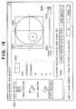
- Fig. 18 shows a dialog when "spot selection” is set as a selection method 2501.
- spot selection is a method of setting a spherical region having the color to be tuned (spot) designated by the mouse on the Lab color space as a range to be tuned. Note that a description of the same items in Fig. 18 as those in Fig. 15 will be omitted.
- reference numeral 2503 denotes an L point which displays the position of the color to be tuned on a color balance that indicates the degree of luminance.
- Reference numeral 2504 denotes an ab point, which displays the position of the color to be tuned on a color wheel expressed by ab color differences.
- Reference numeral 2505 denotes an item used to set the effect level of tuning. In case of spot selection, one effect level corresponding to the diameter of a sphere as the tuning range in the Lab color space is set.
- the color to be tuned is indicated by a dot on the color wheel indicating the ab point 2504, and a tuning range according to the effect level is displayed in a spherical shape to have that dot as the center.
- the L point 2503 displays lines that indicate the tuning range according to the effect level above and below a line that indicates the color to be tuned.
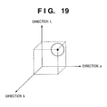
- Fig. 19 shows the way the tuning range spreads in accordance with the set effect level on the Lab color space upon spot selection.
- ⁇ indicates the coordinate position on the color space of the color to be tuned set by the mouse, and the spherical tuning range is set in accordance with the set effect level to have this ⁇ as the center.
- ranges e.g., from 0 to 20, but the present invention is not limited to such specific range.
- Fig. 20 shows a dialog when "whole selection” is set as a selection method 2301.
- "Whole selection” indicates that the whole image, i.e., the whole color space is set as an object to be tuned. Hence, if tuning is executed by "whole selection", no color to be tuned need be designated by the mouse on the preview window. Also, since no tuning range need be set, nothing is displayed on a control area 2303.
- the user can select a desired one of a plurality of selection methods on the color selection dialog, resulting in high operability.
- the color tuning dialog includes a CMYK tuning dialog, Lab tuning dialog, and LCh tuning dialog depending on designation of its tuning method. Note that the default is, e.g., the CMYK tuning dialog.
- Fig. 21 shows a dialog when "CMYK tuning" is selected as a tuning method 2801.
- Reference numeral 2802 denotes a color point, which displays preview and original colors to be tuned on the right and left fields as in the color selection dialog.
- Reference numeral 2803 denotes areas used to tune the ratios of C, M, Y, and K. Each ratio can be set within the range from -20 to +20 to have 0 as a default value, but the present invention is not limited to such specific range.
- a "confirm tuning result on image in real time” check box 2804 If a "confirm tuning result on image in real time” check box 2804 is checked, the tuning result is fed back onto the preview image view and preview chart view in real time to update display. Note that the default of the check box 2804 is check OFF. If a "display selected color” check box 2805 is checked, colors that fall within the tuning range selected on the color selection dialog flash on the preview image view and preview chart view. Note that the default of the check box 2805 is check ON.
- the function of a "confirm tuning result on image” button is enabled when the check box 2804 is not checked, i.e., is OFF. Upon depression of this button, the profile is tuned on the basis of the set tuning values, and the tuning result is fed back onto the preview image view and preview chart view, thus updating display. This button may be grayed out when the check box 2804 is ON.
- a weight setting dialog (to be described later) is displayed.
- the tuning values changed by the user are reset and return to default values.
- the tuning values are settled, and profile tuning ends.
- Fig. 22 shows a dialog when "Lab tuning" is selected as a tuning method 2901. A description of the same items in Fig. 22 as those in Fig. 21 will be omitted.
- Reference numeral 2903 denotes areas used to tune the ratios of L, a, and b. Each ratio can be set within the range from -20 to +20 to have 0 as a default value, but the present invention is not limited to such specific range.
- Fig. 23 shows a dialog when "LCh tuning" is selected as a tuning method 3001. A description of the same items in Fig. 23 as those in Fig. 21 will be omitted.
- Reference numeral 3003 denotes areas used to tune the ratios of L, C, and h. Each ratio can be set within the range from -20 to +20 to have 0 as a default value, but the present invention is not limited to such specific range.
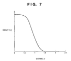
- a weight for the tuning value set using the color tuning dialog is set within the tuning range in the Lab color space set by the color selection dialog. This is to make the boundary of the tuning range indistinctive. More specifically, a weighting function is set in accordance with the set weight, as shown in Fig. 24.
- a weight setting dialog is displayed.
- the weight setting dialog one of weight setting dialogs for whole selection, gamut selection, and spot selection is displayed depending on designation of the selection method on the color selection dialog.
- Fig. 25 shows the weight setting dialog for whole selection, which is displayed when "whole selection" is set as the selection method on the color selection dialog. In case of whole selection, since no weighting is required, no parameters are set.
- Fig. 26 shows the weight setting dialog for gamut selection, which is displayed when "gamut selection" is set as the selection method on the color selection dialog.
- weights can be independently set for L, C, and h. Note that each weight can be set within the range from 1 to 10 to have 3 as a default, but the present invention is not limited to such specific range.
- the tuning amounts on the Lab color space are calculated on the basis of the weights set for L, C, and H. In this case, for example, an LCh correction amount may be calculated from the corresponding weight setting functions, and can be converted into an Lab value.
- Fig. 27 shows the weight setting dialog for spot selection, which is displayed when "spot selection" is set as the selection method on the color selection dialog. As shown in Fig. 27, only one weight can be set and, hence, one weighting function is set. The default of this weight is also 3, and the weight can be set within the range from 1 to 10. However, the present invention is not limited to such specific range.
- an information window 3701 that shows information of the currently displayed original and preview images is superposed, as shown in Fig. 28.
- the information window 3701 has display items "view”, “X-coordinate”, “Y-coordinate”, and “ ⁇ E” as in the gamut selection dialog shown in Fig. 15, and also an item “color reproduction range”, which indicates whether all original image data (output from the target device profile 1102) falls within or outside the color reproduction range of the output device profile (1101D/ 1101S). If this item is "outside", it is determined that the output device profile is inappropriate, and the profile tuning process can be started.
- the information window 3701 has tag areas "CMYK”, “RGB”, “Lab”, “LCh”, and "XYZ", which display various kinds of color space information for the correctly selected color to be tuned. Note that the types of tags are not limited to this example.
- a history window 3702 is also superposed on the preview window.
- the history window 3702 displays a list of information of operations associated with the color selection/tuning process as a history every time such operation is made.
- Each history simultaneously displays an evaluation value of the tuning result.
- As the evaluation value a ⁇ E average value, maximum/minimum value of ⁇ E, or the like can be used, but various other values may be used.
- each history can be assigned a record name, and can be exported to the memory 1012. In this way, a process for undoing the current tuning (to return to a previous operation (previous tuning)) or redoing it during tuning can be made, and an arbitrary tuning stage can be easily reproduced. Also, by importing the history exported to the memory 1012 by designating its record name, it can be easily used upon tuning of another profile.
- the generation result of the output device profile 1101 can be easily confirmed, and tuning based on that result can be easily done.
- the present invention may be applied to either a system constituted by a plurality of devices (e.g., a host computer, interface device, reader, printer, and the like), or an apparatus consisting of a single equipment (e.g., a copying machine, facsimile apparatus, or the like).
- a system constituted by a plurality of devices (e.g., a host computer, interface device, reader, printer, and the like), or an apparatus consisting of a single equipment (e.g., a copying machine, facsimile apparatus, or the like).
- the objects of the present invention are also achieved by supplying a storage medium (or recording medium), which records a program code of a software program that can implement the functions of the above-mentioned embodiments to the system or apparatus, and reading out and executing the program code stored in the storage medium by a computer (or a CPU or MPU) of the system or apparatus.
- a computer or a CPU or MPU
- the program code itself read out from the storage medium implements the functions of the above-mentioned embodiments
- the storage medium which stores the program code constitutes the present invention.
- the functions of the above-mentioned embodiments may be implemented not only by executing the readout program code by the computer but also by some or all of actual processing operations executed by an operating system (OS) running on the computer on the basis of an instruction of the program code.
- OS operating system
- the functions of the above-mentioned embodiments may be implemented by some or all of actual processing operations executed by a CPU or the like arranged in a function extension card or a function extension unit, which is inserted in or connected to the computer, after the program code read out from the storage medium is written in a memory of the extension card or unit.
- a profile that can accurately approximate strong nonlinear output characteristics of a color printer or printing press, and allows accurate color reproduction can be provided.
Landscapes
- Engineering & Computer Science (AREA)
- Multimedia (AREA)
- Signal Processing (AREA)
- Color Image Communication Systems (AREA)
- Facsimile Image Signal Circuits (AREA)
- Color, Gradation (AREA)
- Image Processing (AREA)
Applications Claiming Priority (2)
| Application Number | Priority Date | Filing Date | Title |
|---|---|---|---|
| JP2001280763A JP3890211B2 (ja) | 2001-09-14 | 2001-09-14 | 画像処理方法、画像処理装置、プログラム、記憶媒体 |
| JP2001280763 | 2001-09-14 |
Publications (3)
| Publication Number | Publication Date |
|---|---|
| EP1294177A2 true EP1294177A2 (de) | 2003-03-19 |
| EP1294177A3 EP1294177A3 (de) | 2004-12-15 |
| EP1294177B1 EP1294177B1 (de) | 2009-11-25 |
Family
ID=19104699
Family Applications (1)
| Application Number | Title | Priority Date | Filing Date |
|---|---|---|---|
| EP02256227A Expired - Lifetime EP1294177B1 (de) | 2001-09-14 | 2002-09-09 | Bildverarbeitungsverfahren und -vorrichtung |
Country Status (4)
| Country | Link |
|---|---|
| US (1) | US7385739B2 (de) |
| EP (1) | EP1294177B1 (de) |
| JP (1) | JP3890211B2 (de) |
| DE (1) | DE60234492D1 (de) |
Cited By (15)
| Publication number | Priority date | Publication date | Assignee | Title |
|---|---|---|---|---|
| EP1631058A1 (de) * | 2004-08-25 | 2006-03-01 | Dainippon Screen Mfg. Co., Ltd. | System, Verfahren und Programm zur Korrektur und Kontrolle eines Probedrucks |
| EP1675380A1 (de) * | 2004-12-21 | 2006-06-28 | Samsung Electronics Co., Ltd. | Tragbares Gerät mit direkter Druckfunktion |
| EP1871089A2 (de) | 2006-06-23 | 2007-12-26 | Fujitsu Ltd. | Programm, Vorrichtung und Verfahren zur Farbeinstellung |
| WO2008033694A1 (en) | 2006-09-11 | 2008-03-20 | Electronics For Imaging, Inc. | Apparatus and methods for editing hue and saturation in color profiles |
| WO2008033692A3 (en) * | 2006-09-11 | 2008-06-26 | Electronics For Imaging Inc | Apparatus and methods for selective color editing of color profiles |
| WO2009146296A1 (en) * | 2008-05-28 | 2009-12-03 | Apple Inc. | Color correcting method and apparatus |
| US7852534B2 (en) | 2005-09-27 | 2010-12-14 | Samsung Electronics Co., Ltd. | Apparatus and method for creating preview image of object |
| US8199368B2 (en) | 2007-11-02 | 2012-06-12 | Fujifilm Corporation | Image data correcting apparatus, computer-readable image data correcting program storage medium, image data correcting method and printing system |
| US8243326B2 (en) | 2006-09-11 | 2012-08-14 | Electronics For Imaging, Inc. | Methods and apparatus for color profile editing |
| US8326035B2 (en) | 2001-12-03 | 2012-12-04 | Apple Inc. | Method and apparatus for color correction |
| US8619093B2 (en) | 2010-07-20 | 2013-12-31 | Apple Inc. | Keying an image |
| US8675009B2 (en) | 2010-07-20 | 2014-03-18 | Apple Inc. | Keying an image in three dimensions |
| US8743139B2 (en) | 2010-07-20 | 2014-06-03 | Apple Inc. | Automatically keying an image |
| EP2744190A1 (de) * | 2012-12-13 | 2014-06-18 | Samsung Electronics Co., Ltd | Drucksteuerungsvorrichtung, Bilderzeugungsvorrichtung und Verfahren zur Farbüberarbeitung |
| EP3413554A1 (de) * | 2017-06-06 | 2018-12-12 | Seiko Epson Corporation | Verfahren und system zur profilanpassung |
Families Citing this family (60)
| Publication number | Priority date | Publication date | Assignee | Title |
|---|---|---|---|---|
| US20110229023A1 (en) * | 2002-11-01 | 2011-09-22 | Tenebraex Corporation | Technique for enabling color blind persons to distinguish between various colors |
| US7145571B2 (en) * | 2002-11-01 | 2006-12-05 | Tenebraex Corporation | Technique for enabling color blind persons to distinguish between various colors |
| US20050156942A1 (en) * | 2002-11-01 | 2005-07-21 | Jones Peter W.J. | System and method for identifying at least one color for a user |
| US7215343B2 (en) * | 2003-01-30 | 2007-05-08 | Eastman Kodak Company | Color correction using a device-dependent display profile |
| WO2005006772A1 (ja) * | 2003-07-09 | 2005-01-20 | Matsushita Electric Industrial Co., Ltd. | 画像表示装置及び画像表示方法 |
| US7129958B2 (en) * | 2003-08-28 | 2006-10-31 | Canon Kabushiki Kaisha | Color management with tiered caching scheme |
| DE602004021032D1 (de) * | 2003-12-03 | 2009-06-18 | Tenebraex Corp | System und verfahren zur identifizierung mindestens einer farbe für einen anwender |
| US7483170B2 (en) * | 2004-05-05 | 2009-01-27 | Canon Kabushiki Kaisha | Generation of color measured data from transform-based color profiles |
| US7593147B2 (en) * | 2004-05-26 | 2009-09-22 | Fujifilm Corporation | Output apparatus, color conversion method, and machine readable medium storing program |
| JP4506323B2 (ja) * | 2004-07-16 | 2010-07-21 | セイコーエプソン株式会社 | 誤差情報取得装置、誤差情報取得方法、誤差情報取得プログラム、印刷制御装置、印刷制御方法及び印刷制御プログラム |
| US20060055945A1 (en) * | 2004-09-13 | 2006-03-16 | Fazakerly William B | Color-mapped data display |
| JP4327059B2 (ja) * | 2004-10-20 | 2009-09-09 | 株式会社東芝 | カラー画像修正処理装置およびカラー画像修正処理方法 |
| US7525685B2 (en) * | 2004-10-27 | 2009-04-28 | Avago Technologies General Ip (Singapore) Pte. Ltd. | True-color computer monitor preview of a color print |
| US7626742B2 (en) * | 2005-02-16 | 2009-12-01 | Samsung Electronics Co., Ltd. | Color data conversion apparatus and method using gamut boundary descriptors |
| JP4325575B2 (ja) * | 2005-03-18 | 2009-09-02 | セイコーエプソン株式会社 | モノトーン画像のための基準色調設定 |
| JP4592090B2 (ja) * | 2005-06-22 | 2010-12-01 | キヤノン株式会社 | 色処理方法およびその装置 |
| US7737991B2 (en) * | 2005-08-09 | 2010-06-15 | Basf Corporation | Method of visualizing a color deviation |
| KR100739731B1 (ko) | 2005-09-06 | 2007-07-13 | 삼성전자주식회사 | 표시된 화상의 인쇄를 위한 화상처리 방법 및 장치 |
| JP4732142B2 (ja) * | 2005-11-17 | 2011-07-27 | キヤノン株式会社 | 画像処理方法、プログラム、及び画像処理装置 |
| CA2677956A1 (en) * | 2006-02-28 | 2007-09-07 | Ernest Daniel Miller | Color management of digital files and images for printing |
| JP4757081B2 (ja) * | 2006-04-06 | 2011-08-24 | キヤノン株式会社 | 画像処理方法及び装置 |
| JP4974586B2 (ja) * | 2006-05-24 | 2012-07-11 | オリンパス株式会社 | 顕微鏡用撮像装置 |
| JP4715642B2 (ja) * | 2006-06-06 | 2011-07-06 | 富士ゼロックス株式会社 | 色変換装置、方法及びプログラム |
| US20080043265A1 (en) * | 2006-06-21 | 2008-02-21 | Gyong-Ock Kim | System and method of adjusting colors of print data |
| JP4931219B2 (ja) * | 2007-03-02 | 2012-05-16 | キヤノン株式会社 | 情報処理装置及び情報処理方法 |
| EP2143262B1 (de) * | 2007-05-04 | 2015-07-01 | Esko Software Bvba | Benutzerkonfigurierbares gamut-mapping und umwandlung von bildern aus einem quellfarbbereich in einen zielfarbereich mit primären und redundanten farben |
| JP5006757B2 (ja) * | 2007-08-07 | 2012-08-22 | キヤノン株式会社 | 画像処理装置及び画像処理方法 |
| JP4999598B2 (ja) * | 2007-08-10 | 2012-08-15 | キヤノン株式会社 | 画像処理装置及びその制御方法 |
| JP2009113213A (ja) * | 2007-11-01 | 2009-05-28 | Mitsubishi Heavy Ind Ltd | 印刷模擬システム及び印刷模擬方法並びに印刷管理システム |
| US20090157906A1 (en) * | 2007-12-14 | 2009-06-18 | Ricoh Company, Ltd. | Information processing device, information processing device controlling method, and computer-readable recording medium |
| JP5023036B2 (ja) * | 2008-10-21 | 2012-09-12 | 大日本スクリーン製造株式会社 | プロファイル生成装置、プロファイル生成プログラム、プロファイル生成方法、画像処理装置、画像処理プログラム、および画像処理方法 |
| US20100157331A1 (en) * | 2008-12-23 | 2010-06-24 | Vladimir Shestak | Color Smoothing Mechanism for an Ink Minimizing Profile Making Tool |
| US20100201998A1 (en) * | 2009-02-11 | 2010-08-12 | Quach Tony T | System and method for display matched color printer calibration |
| JP5381380B2 (ja) * | 2009-06-18 | 2014-01-08 | 富士ゼロックス株式会社 | 画像処理装置、画像形成システム、およびプログラム |
| JP5303420B2 (ja) * | 2009-10-01 | 2013-10-02 | 株式会社キーエンス | 光学的情報読取装置の撮像条件設定装置及び撮像条件設定方法 |
| JP5531836B2 (ja) * | 2009-11-10 | 2014-06-25 | 株式会社リコー | 画像処理装置及びプログラム |
| US20110286061A1 (en) * | 2010-05-20 | 2011-11-24 | Xerox Corporation | Smart mode color workflow |
| JP5682239B2 (ja) * | 2010-11-05 | 2015-03-11 | 富士ゼロックス株式会社 | 色調整装置、画像形成装置、画像形成システム、及び色調整プログラム |
| JP5747644B2 (ja) * | 2011-05-09 | 2015-07-15 | コニカミノルタ株式会社 | 色変換装置、色変換装置の色調整方法及びプログラム |
| JP2011254559A (ja) * | 2011-09-21 | 2011-12-15 | Dainippon Printing Co Ltd | プロファイル利用支援装置、プロファイル利用支援方法、プログラム |
| JP6089491B2 (ja) * | 2011-11-30 | 2017-03-08 | 株式会社リコー | 画像処理装置、画像処理システム、画像処理方法、プログラム及び記憶媒体 |
| JP5774533B2 (ja) * | 2012-03-29 | 2015-09-09 | 東芝テック株式会社 | ラベルプリンタ |
| JP5342038B2 (ja) * | 2012-05-14 | 2013-11-13 | キヤノン株式会社 | 画像処理装置及び画像処理装置の制御方法 |
| JP5994586B2 (ja) * | 2012-11-07 | 2016-09-21 | コニカミノルタ株式会社 | 色変換テーブルの調整方法、プログラム及びプログラムを格納するコンピューター読み取り可能な媒体 |
| JP2014099829A (ja) * | 2012-11-16 | 2014-05-29 | Canon Inc | 画像処理装置および画像処理方法ならびに画像処理を実行するプログラム |
| JP6048655B2 (ja) * | 2012-12-11 | 2016-12-21 | セイコーエプソン株式会社 | 記録データ生成装置、記録システム、プログラム、記録データ生成方法及び画像データ表示方法 |
| USD746856S1 (en) * | 2013-02-07 | 2016-01-05 | Tencent Technology (Shenzhen) Company Limited | Display screen portion with an animated graphical user interface |
| GB2519364A (en) * | 2013-10-21 | 2015-04-22 | Nokia Corp | Method, apparatus and computer program product for facilitating color communication |
| CN105760040B (zh) * | 2014-12-17 | 2019-06-11 | 青岛海信移动通信技术股份有限公司 | 一种窗口预览效果的方法和装置 |
| JP6512884B2 (ja) | 2015-03-20 | 2019-05-15 | キヤノン株式会社 | 色変換処理装置および色変換処理方法 |
| US9906676B2 (en) | 2015-03-26 | 2018-02-27 | Canon Kabushiki Kaisha | Image processing apparatus and image processing method |
| JP6554413B2 (ja) * | 2015-12-21 | 2019-07-31 | オリンパス株式会社 | 色調整装置 |
| JP2017123588A (ja) * | 2016-01-08 | 2017-07-13 | 富士ゼロックス株式会社 | 色処理装置、画像形成装置および画像形成システム |
| JP2018026696A (ja) | 2016-08-10 | 2018-02-15 | 富士ゼロックス株式会社 | 画像処理装置、画像処理方法、画像処理システムおよびプログラム |
| JP6969167B2 (ja) * | 2017-06-06 | 2021-11-24 | セイコーエプソン株式会社 | プロファイル調整方法、プロファイル調整プログラム、プロファイル調整装置、及び、プロファイル調整システム |
| US10602026B2 (en) * | 2017-06-20 | 2020-03-24 | Fuji Xerox Co., Ltd. | Image processing apparatus, image processing method, and non-transitory computer readable medium |
| JP6939455B2 (ja) * | 2017-06-20 | 2021-09-22 | 富士フイルムビジネスイノベーション株式会社 | 画像処理装置、画像処理方法、画像処理システムおよびプログラム |
| JP7110840B2 (ja) * | 2018-09-06 | 2022-08-02 | 株式会社リコー | プログラム、画像形成装置、情報処理装置、及び情報処理システム |
| JP2020057913A (ja) * | 2018-10-01 | 2020-04-09 | 東芝テック株式会社 | 画像処理装置及び画像処理方法 |
| JP7358917B2 (ja) * | 2019-10-31 | 2023-10-11 | 株式会社リコー | 印刷システム、プログラム、画像形成装置、及び、印刷方法 |
Family Cites Families (32)
| Publication number | Priority date | Publication date | Assignee | Title |
|---|---|---|---|---|
| JP3092711B2 (ja) | 1990-09-11 | 2000-09-25 | キヤノン株式会社 | 出力制御装置及び方法 |
| JP2996522B2 (ja) | 1991-03-14 | 2000-01-11 | キヤノン株式会社 | 画像処理方法 |
| US5739928A (en) * | 1991-09-12 | 1998-04-14 | Eastman Kodak Company | Technique particularly suited for use in a print preview function for adapting CRT colorimetry to ambient lighting conditions |
| JPH05128224A (ja) | 1991-11-08 | 1993-05-25 | Fujitsu Ltd | カラー画像の色抽出装置および方法 |
| US5416890A (en) * | 1991-12-11 | 1995-05-16 | Xerox Corporation | Graphical user interface for controlling color gamut clipping |
| JPH0787345A (ja) | 1993-09-17 | 1995-03-31 | Hitachi Koki Co Ltd | カラーマッチング方法及びその装置 |
| US5748342A (en) * | 1994-04-18 | 1998-05-05 | Canon Kabushiki Kaisha | Image processing apparatus and method |
| US5627950A (en) * | 1994-09-16 | 1997-05-06 | Apple Computer, Inc. | Real-time three-dimensional color look-up table interactive editor system and method |
| JPH08130655A (ja) | 1994-10-31 | 1996-05-21 | Canon Inc | 画像処理方法及び装置 |
| JPH08274997A (ja) | 1995-03-30 | 1996-10-18 | Canon Inc | 画像処理装置及び方法 |
| JP2914227B2 (ja) | 1995-07-11 | 1999-06-28 | 富士ゼロックス株式会社 | 画像処理装置および画像処理方法 |
| JP3163987B2 (ja) | 1995-09-04 | 2001-05-08 | 富士ゼロックス株式会社 | 画像処理装置およびガミュート調整方法 |
| JPH09186905A (ja) | 1995-12-27 | 1997-07-15 | Ricoh Co Ltd | 色補正装置 |
| JPH09186907A (ja) | 1996-01-08 | 1997-07-15 | Matsushita Electric Ind Co Ltd | 色調整方法 |
| JPH09270925A (ja) | 1996-04-01 | 1997-10-14 | Canon Inc | 画像処理装置及び方法 |
| JPH09326938A (ja) | 1996-06-07 | 1997-12-16 | Canon Inc | 画像処理装置及びその方法 |
| US5797397A (en) * | 1996-11-25 | 1998-08-25 | Hewlett-Packard Company | Ultrasound imaging system and method using intensity highlighting to facilitate tissue differentiation |
| JPH114353A (ja) | 1997-06-13 | 1999-01-06 | Canon Inc | 画像処理方法および装置 |
| JP3851448B2 (ja) | 1997-06-17 | 2006-11-29 | ペンタックス株式会社 | 色調調整装置 |
| JP4347435B2 (ja) | 1998-06-26 | 2009-10-21 | リコーItソリューションズ株式会社 | 色修正方法およびそれを格納した記録媒体 |
| JP3305265B2 (ja) * | 1998-07-24 | 2002-07-22 | キヤノン株式会社 | 画像処理装置およびその方法 |
| JP4077938B2 (ja) | 1998-07-27 | 2008-04-23 | キヤノン株式会社 | カラーパッチに関する測色値の推定方法、該方法を利用したデバイス・プロファイルの作成方法および画像処理装置 |
| JP3706743B2 (ja) | 1998-07-31 | 2005-10-19 | キヤノン株式会社 | 関心領域抽出方法及び装置並びに記憶媒体 |
| US6236406B1 (en) * | 1998-10-21 | 2001-05-22 | Sony Corporation | Three-dimensional color space display |
| JP3291259B2 (ja) | 1998-11-11 | 2002-06-10 | キヤノン株式会社 | 画像処理方法および記録媒体 |
| JP3691322B2 (ja) | 1999-01-18 | 2005-09-07 | 富士写真フイルム株式会社 | 色補正方法 |
| US6599244B1 (en) * | 1999-12-23 | 2003-07-29 | Siemens Medical Solutions, Usa, Inc. | Ultrasound system and method for direct manipulation interface |
| US6477271B1 (en) * | 2000-04-07 | 2002-11-05 | Avid Technology, Inc. | Secondary color modification of a digital image |
| US6525721B1 (en) * | 2000-05-05 | 2003-02-25 | Xerox Corporation | Color profile management and color collection management, navigation and visual design |
| JP3720691B2 (ja) * | 2000-09-12 | 2005-11-30 | キヤノン株式会社 | 色処理方法および装置 |
| JP3420560B2 (ja) * | 2000-09-12 | 2003-06-23 | キヤノン株式会社 | 画像処理方法および記録媒体 |
| JP2002187314A (ja) * | 2000-09-12 | 2002-07-02 | Canon Inc | 画像処理装置およびその方法、予測方法、表示方法、並びに、管理方法 |
-
2001
- 2001-09-14 JP JP2001280763A patent/JP3890211B2/ja not_active Expired - Fee Related
-
2002
- 2002-09-09 EP EP02256227A patent/EP1294177B1/de not_active Expired - Lifetime
- 2002-09-09 DE DE60234492T patent/DE60234492D1/de not_active Expired - Lifetime
- 2002-09-11 US US10/238,790 patent/US7385739B2/en not_active Expired - Fee Related
Cited By (24)
| Publication number | Priority date | Publication date | Assignee | Title |
|---|---|---|---|---|
| US8326035B2 (en) | 2001-12-03 | 2012-12-04 | Apple Inc. | Method and apparatus for color correction |
| EP1631058A1 (de) * | 2004-08-25 | 2006-03-01 | Dainippon Screen Mfg. Co., Ltd. | System, Verfahren und Programm zur Korrektur und Kontrolle eines Probedrucks |
| EP1675380A1 (de) * | 2004-12-21 | 2006-06-28 | Samsung Electronics Co., Ltd. | Tragbares Gerät mit direkter Druckfunktion |
| US8169675B2 (en) | 2005-09-27 | 2012-05-01 | Samsung Electronics Co., Ltd. | Apparatus and method for creating preview image of object |
| US7852534B2 (en) | 2005-09-27 | 2010-12-14 | Samsung Electronics Co., Ltd. | Apparatus and method for creating preview image of object |
| US7800781B2 (en) | 2006-06-23 | 2010-09-21 | Fujitsu Limited | Recording medium and color adjusting apparatus |
| EP1871089A2 (de) | 2006-06-23 | 2007-12-26 | Fujitsu Ltd. | Programm, Vorrichtung und Verfahren zur Farbeinstellung |
| EP1871089A3 (de) * | 2006-06-23 | 2008-12-03 | Fujitsu Ltd. | Programm, Vorrichtung und Verfahren zur Farbeinstellung |
| WO2008033694A1 (en) | 2006-09-11 | 2008-03-20 | Electronics For Imaging, Inc. | Apparatus and methods for editing hue and saturation in color profiles |
| US7598964B2 (en) | 2006-09-11 | 2009-10-06 | Electronics For Imaging, Inc. | Apparatus and methods for editing hue and saturation in color profiles |
| US8013871B2 (en) | 2006-09-11 | 2011-09-06 | Electronics For Imaging, Inc. | Apparatus and methods for selective color editing of color profiles |
| WO2008033692A3 (en) * | 2006-09-11 | 2008-06-26 | Electronics For Imaging Inc | Apparatus and methods for selective color editing of color profiles |
| US8243326B2 (en) | 2006-09-11 | 2012-08-14 | Electronics For Imaging, Inc. | Methods and apparatus for color profile editing |
| US8199368B2 (en) | 2007-11-02 | 2012-06-12 | Fujifilm Corporation | Image data correcting apparatus, computer-readable image data correcting program storage medium, image data correcting method and printing system |
| WO2009146296A1 (en) * | 2008-05-28 | 2009-12-03 | Apple Inc. | Color correcting method and apparatus |
| US8401284B2 (en) | 2008-05-28 | 2013-03-19 | Apple Inc. | Color correcting method and apparatus |
| US8619093B2 (en) | 2010-07-20 | 2013-12-31 | Apple Inc. | Keying an image |
| US8675009B2 (en) | 2010-07-20 | 2014-03-18 | Apple Inc. | Keying an image in three dimensions |
| US8743139B2 (en) | 2010-07-20 | 2014-06-03 | Apple Inc. | Automatically keying an image |
| EP2744190A1 (de) * | 2012-12-13 | 2014-06-18 | Samsung Electronics Co., Ltd | Drucksteuerungsvorrichtung, Bilderzeugungsvorrichtung und Verfahren zur Farbüberarbeitung |
| EP2863621A3 (de) * | 2012-12-13 | 2015-05-27 | Samsung Electronics Co., Ltd | Drucksteuerungsvorrichtung, Bilderzeugungsvorrichtung und Verfahren zur Farbüberarbeitung |
| US9098792B2 (en) | 2012-12-13 | 2015-08-04 | Samsung Electronics Co., Ltd. | Print controlling apparatus, image forming apparatus, method of color revising and computer-readable recording medium |
| EP3413554A1 (de) * | 2017-06-06 | 2018-12-12 | Seiko Epson Corporation | Verfahren und system zur profilanpassung |
| US10447897B2 (en) | 2017-06-06 | 2019-10-15 | Seiko Epson Corporation | Profile adjustment method and profile adjustment system |
Also Published As
| Publication number | Publication date |
|---|---|
| EP1294177B1 (de) | 2009-11-25 |
| JP3890211B2 (ja) | 2007-03-07 |
| US20030053094A1 (en) | 2003-03-20 |
| EP1294177A3 (de) | 2004-12-15 |
| JP2003087591A (ja) | 2003-03-20 |
| US7385739B2 (en) | 2008-06-10 |
| DE60234492D1 (de) | 2010-01-07 |
Similar Documents
| Publication | Publication Date | Title |
|---|---|---|
| US7385739B2 (en) | Image processing method and apparatus for color conversion accommodating device non-linearity | |
| JP4120841B2 (ja) | プロジェクタの色補正方法 | |
| US6081254A (en) | Color correction system of imaging apparatus | |
| EP0881826B1 (de) | Bildverarbeitungsverfahren und -gerät | |
| US6611621B2 (en) | Image processing method and apparatus, and recording medium | |
| KR100816973B1 (ko) | 통합 컬러 매칭 프로세서를 구비한 컬러 디스플레이 장치 및 방법 | |
| US20030133138A1 (en) | Image processing method and apparatus | |
| US20010012396A1 (en) | Image process method, image process apparatus and storage medium | |
| JP3403157B2 (ja) | 画像処理装置およびその方法 | |
| KR101314230B1 (ko) | 화상처리장치 및 그 화상처리방법 | |
| EP1401191A1 (de) | Bildverarbeitungseinrichtung, bildverarbeitungsverfahren, programm und aufzeichnungsmedium | |
| US6829058B1 (en) | Color matching, and calibrating a color-matching profile, preferably using a client-server architecture | |
| JP3990859B2 (ja) | 色処理方法およびその装置 | |
| US20080174798A1 (en) | Color-management apparatus and method | |
| JP2003219176A (ja) | 画像処理装置、画像処理システム、画像処理方法、記憶媒体、及びプログラム | |
| JPH11275376A (ja) | 色彩データ保持方法およびカラーマネージメント方法 | |
| US20060001892A1 (en) | Image processing method and image processing device | |
| JP2008177783A (ja) | 色変換装置及びプログラム | |
| EP1229733A2 (de) | System und Verfahren zur Farbraumumsetzung durch einen zusammengesetzten Farbraum | |
| Fleming et al. | Color management and ICC profiles; can’t live without it so learn to live with it! | |
| JPH10250153A (ja) | カラー画像出力装置 | |
| JP4603665B2 (ja) | 色処理装置およびその方法 | |
| JP4595771B2 (ja) | 色変換装置 | |
| JP4545995B2 (ja) | 画像処理方法及び画像処理装置 | |
| JP3292519B2 (ja) | 画像処理装置 |
Legal Events
| Date | Code | Title | Description |
|---|---|---|---|
| PUAI | Public reference made under article 153(3) epc to a published international application that has entered the european phase |
Free format text: ORIGINAL CODE: 0009012 |
|
| AK | Designated contracting states |
Designated state(s): AT BE BG CH CY CZ DE DK EE ES FI FR GB GR IE IT LI LU MC NL PT SE SK TR Kind code of ref document: A2 Designated state(s): AT BE BG CH CY CZ DE DK EE ES FI FR GB GR IE IT LI LU MC NL PT SE SK TR |
|
| AX | Request for extension of the european patent |
Extension state: AL LT LV MK RO SI |
|
| PUAL | Search report despatched |
Free format text: ORIGINAL CODE: 0009013 |
|
| AK | Designated contracting states |
Kind code of ref document: A3 Designated state(s): AT BE BG CH CY CZ DE DK EE ES FI FR GB GR IE IT LI LU MC NL PT SE SK TR |
|
| AX | Request for extension of the european patent |
Extension state: AL LT LV MK RO SI |
|
| 17P | Request for examination filed |
Effective date: 20050429 |
|
| 17Q | First examination report despatched |
Effective date: 20050622 |
|
| AKX | Designation fees paid |
Designated state(s): CH DE FR GB IT LI |
|
| 17Q | First examination report despatched |
Effective date: 20050622 |
|
| GRAP | Despatch of communication of intention to grant a patent |
Free format text: ORIGINAL CODE: EPIDOSNIGR1 |
|
| GRAS | Grant fee paid |
Free format text: ORIGINAL CODE: EPIDOSNIGR3 |
|
| GRAA | (expected) grant |
Free format text: ORIGINAL CODE: 0009210 |
|
| AK | Designated contracting states |
Kind code of ref document: B1 Designated state(s): CH DE FR GB IT LI |
|
| REG | Reference to a national code |
Ref country code: GB Ref legal event code: FG4D |
|
| REG | Reference to a national code |
Ref country code: CH Ref legal event code: EP |
|
| REF | Corresponds to: |
Ref document number: 60234492 Country of ref document: DE Date of ref document: 20100107 Kind code of ref document: P |
|
| PLBE | No opposition filed within time limit |
Free format text: ORIGINAL CODE: 0009261 |
|
| STAA | Information on the status of an ep patent application or granted ep patent |
Free format text: STATUS: NO OPPOSITION FILED WITHIN TIME LIMIT |
|
| 26N | No opposition filed |
Effective date: 20100826 |
|
| PG25 | Lapsed in a contracting state [announced via postgrant information from national office to epo] |
Ref country code: IT Free format text: LAPSE BECAUSE OF FAILURE TO SUBMIT A TRANSLATION OF THE DESCRIPTION OR TO PAY THE FEE WITHIN THE PRESCRIBED TIME-LIMIT Effective date: 20091125 |
|
| REG | Reference to a national code |
Ref country code: CH Ref legal event code: PL |
|
| REG | Reference to a national code |
Ref country code: FR Ref legal event code: ST Effective date: 20110531 |
|
| PG25 | Lapsed in a contracting state [announced via postgrant information from national office to epo] |
Ref country code: CH Free format text: LAPSE BECAUSE OF NON-PAYMENT OF DUE FEES Effective date: 20100930 Ref country code: FR Free format text: LAPSE BECAUSE OF NON-PAYMENT OF DUE FEES Effective date: 20100930 Ref country code: LI Free format text: LAPSE BECAUSE OF NON-PAYMENT OF DUE FEES Effective date: 20100930 |
|
| PGFP | Annual fee paid to national office [announced via postgrant information from national office to epo] |
Ref country code: GB Payment date: 20150922 Year of fee payment: 14 Ref country code: DE Payment date: 20150930 Year of fee payment: 14 |
|
| REG | Reference to a national code |
Ref country code: DE Ref legal event code: R119 Ref document number: 60234492 Country of ref document: DE |
|
| GBPC | Gb: european patent ceased through non-payment of renewal fee |
Effective date: 20160909 |
|
| PG25 | Lapsed in a contracting state [announced via postgrant information from national office to epo] |
Ref country code: GB Free format text: LAPSE BECAUSE OF NON-PAYMENT OF DUE FEES Effective date: 20160909 Ref country code: DE Free format text: LAPSE BECAUSE OF NON-PAYMENT OF DUE FEES Effective date: 20170401 |