EP1294460B1 - Vorrichtung zum auffangen zu beseitigender produkte, zur industriellen und medizinischen anwendung - Google Patents
Vorrichtung zum auffangen zu beseitigender produkte, zur industriellen und medizinischen anwendung Download PDFInfo
- Publication number
- EP1294460B1 EP1294460B1 EP01947552A EP01947552A EP1294460B1 EP 1294460 B1 EP1294460 B1 EP 1294460B1 EP 01947552 A EP01947552 A EP 01947552A EP 01947552 A EP01947552 A EP 01947552A EP 1294460 B1 EP1294460 B1 EP 1294460B1
- Authority
- EP
- European Patent Office
- Prior art keywords
- container
- walls
- duct
- inflatable
- products
- Prior art date
- Legal status (The legal status is an assumption and is not a legal conclusion. Google has not performed a legal analysis and makes no representation as to the accuracy of the status listed.)
- Expired - Lifetime
Links
- 239000007788 liquid Substances 0.000 claims description 9
- 238000011109 contamination Methods 0.000 description 3
- 238000011084 recovery Methods 0.000 description 3
- 238000012958 reprocessing Methods 0.000 description 3
- 238000012423 maintenance Methods 0.000 description 2
- QSHDDOUJBYECFT-UHFFFAOYSA-N mercury Chemical compound [Hg] QSHDDOUJBYECFT-UHFFFAOYSA-N 0.000 description 2
- 229910052753 mercury Inorganic materials 0.000 description 2
- 230000001954 sterilising effect Effects 0.000 description 2
- 238000004659 sterilization and disinfection Methods 0.000 description 2
- 239000002699 waste material Substances 0.000 description 2
- 229910000497 Amalgam Inorganic materials 0.000 description 1
- 206010011409 Cross infection Diseases 0.000 description 1
- 238000004026 adhesive bonding Methods 0.000 description 1
- 239000010796 biological waste Substances 0.000 description 1
- 230000005587 bubbling Effects 0.000 description 1
- 239000000645 desinfectant Substances 0.000 description 1
- 239000003814 drug Substances 0.000 description 1
- 230000000694 effects Effects 0.000 description 1
- 238000001914 filtration Methods 0.000 description 1
- 208000015181 infectious disease Diseases 0.000 description 1
- 238000009434 installation Methods 0.000 description 1
- 239000000463 material Substances 0.000 description 1
- 230000000717 retained effect Effects 0.000 description 1
- 238000007789 sealing Methods 0.000 description 1
- 239000007787 solid Substances 0.000 description 1
- 231100000331 toxic Toxicity 0.000 description 1
- 230000002588 toxic effect Effects 0.000 description 1
- 239000010891 toxic waste Substances 0.000 description 1
- 238000011144 upstream manufacturing Methods 0.000 description 1
- 239000002351 wastewater Substances 0.000 description 1
- 238000003466 welding Methods 0.000 description 1
Images


Classifications
-
- B—PERFORMING OPERATIONS; TRANSPORTING
- B01—PHYSICAL OR CHEMICAL PROCESSES OR APPARATUS IN GENERAL
- B01D—SEPARATION
- B01D17/00—Separation of liquids, not provided for elsewhere, e.g. by thermal diffusion
-
- B—PERFORMING OPERATIONS; TRANSPORTING
- B01—PHYSICAL OR CHEMICAL PROCESSES OR APPARATUS IN GENERAL
- B01D—SEPARATION
- B01D17/00—Separation of liquids, not provided for elsewhere, e.g. by thermal diffusion
- B01D17/02—Separation of non-miscible liquids
- B01D17/0208—Separation of non-miscible liquids by sedimentation
-
- B—PERFORMING OPERATIONS; TRANSPORTING
- B01—PHYSICAL OR CHEMICAL PROCESSES OR APPARATUS IN GENERAL
- B01D—SEPARATION
- B01D21/00—Separation of suspended solid particles from liquids by sedimentation
-
- B—PERFORMING OPERATIONS; TRANSPORTING
- B01—PHYSICAL OR CHEMICAL PROCESSES OR APPARATUS IN GENERAL
- B01D—SEPARATION
- B01D21/00—Separation of suspended solid particles from liquids by sedimentation
- B01D21/0003—Making of sedimentation devices, structural details thereof, e.g. prefabricated parts
-
- B—PERFORMING OPERATIONS; TRANSPORTING
- B01—PHYSICAL OR CHEMICAL PROCESSES OR APPARATUS IN GENERAL
- B01D—SEPARATION
- B01D21/00—Separation of suspended solid particles from liquids by sedimentation
- B01D21/0012—Settling tanks making use of filters, e.g. by floating layers of particulate material
-
- B—PERFORMING OPERATIONS; TRANSPORTING
- B01—PHYSICAL OR CHEMICAL PROCESSES OR APPARATUS IN GENERAL
- B01D—SEPARATION
- B01D21/00—Separation of suspended solid particles from liquids by sedimentation
- B01D21/003—Sedimentation tanks provided with a plurality of compartments separated by a partition wall
-
- B—PERFORMING OPERATIONS; TRANSPORTING
- B01—PHYSICAL OR CHEMICAL PROCESSES OR APPARATUS IN GENERAL
- B01D—SEPARATION
- B01D21/00—Separation of suspended solid particles from liquids by sedimentation
- B01D21/24—Feed or discharge mechanisms for settling tanks
- B01D21/2405—Feed mechanisms for settling tanks
-
- B—PERFORMING OPERATIONS; TRANSPORTING
- B01—PHYSICAL OR CHEMICAL PROCESSES OR APPARATUS IN GENERAL
- B01D—SEPARATION
- B01D2221/00—Applications of separation devices
- B01D2221/10—Separation devices for use in medical, pharmaceutical or laboratory applications, e.g. separating amalgam from dental treatment residues
Definitions
- the present invention relates to a device for trapping products to be eliminated, for industrial or medical use.
- Known trapping devices are generally of complex and expensive structure. They include disposable or washable parts, such as filters or bags, but also fixed parts that remain contamina- tor even if their maintenance is ensured perfectly, since their sterilization can not be assured. In addition, these devices can not guarantee a 100% trapping of biological and toxic waste, such as mercury, which must however be eliminated in perfectly controlled dies.
- the present invention aims to provide a particularly simple and economical device that guarantees a perfect safety vis-à-vis the risk of contamination.
- the subject of the present invention is a device for trapping products to be eliminated, constituted by a closed container provided with a product supply duct and a suction duct, characterized in that said container comprises at least one wall inflatable which is flexible when deflated and makes the container space-saving and rigid when inflated, the container then being rigid enough that suction through the suction pipe creates a vacuum that sucks products to be eliminated in the container through the product supply duct.
- the inflation of said at least one wall gives the container sufficient rigidity to form at least a portion of its frame.
- the product trapping device can suck up the products to be eliminated, by simple depression of its interior.
- the device comprises two inflatable walls which form two opposite walls of the closed container and are supplemented by flexible walls stretched between them after inflation and / or by rigid flat walls.
- the device comprises a single inflatable wall and, opposite it, an articulation connecting two rigid walls joining said inflatable wall, as well as flexible walls stretched between the inflatable and rigid walls.
- the inflatable walls are toric and define the periphery of the container.
- the device comprises a suction duct intended to be connected to a vacuum pump intended to create a vacuum in the closed container.
- the device according to the invention can be made of a sufficiently economical material for said device to be disposable, the unique use of the device being the most effective parade to the risk of infection or contamination.
- the device according to the invention finds particular application in medicine, and more particularly in hospital, where it can be a means of fighting against nosocomial infections.
- the device according to the invention When its or its inflatable walls are deflated, the device according to the invention is compact. It may for example be in the form of a flattened rectangle configuration that facilitates storage.
- the device according to the invention can in particular be combined with the disposable unit described in the French patent application published under No. 2,775,184 in the name of the same applicant.
- this combination provides a complete equipment that solves both the problems of connection and the problems of disposal of biological and toxic products, such as mercury in wastewater.
- the device according to the invention provides a security vis-à-vis pollution and contamination problems because its operation is not based on filtering products but on their trapping.
- the container Once the container is filled, its product supply duct may be sealed, for example by heat sealing, so that the trapping of the products becomes final, and an identification, for example by bar code, may be carried on the device to facilitate its collection. , its traceability and the reprocessing of the trapped products.
- an identification for example by bar code
- the suction duct is provided with a filter whose function is to maintain inside the container vaporized products which could, in the absence of such a filter, escape because of the introduction of air or new waste into the container.
- This filter may, in addition, be constituted by or contain a disinfectant product for purifying the air escaping from the container.
- the suction duct is provided with a safety valve which prevents the container from overflowing through this duct in case of complete filling with a liquid.
- Such a valve may for example be constituted by a floating ball held opposite the mouth, in the form of a seat, of the duct and capable of closing it by being pressed against said seat when the liquid level reaches a certain height. in the container.
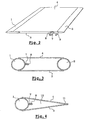
- the device of FIG. 1 comprises a closed container formed by two opposite inflatable walls 1, 2, joined by two rigid flat walls 3, 4, by a flexible base 5 and by a flexible upper wall 6.
- a product supply duct 7 passes through the upper wall 6 and extends inside the container to the vicinity of its bottom 5.
- a suction duct 8 also passes through the wall 6 and opens into the upper part of the container.
- the suction duct 8 is intended to be connected to a vacuum pump (not shown) which creates a vacuum in the container and forces the suction of the products through the supply duct 7.
- An inflation duct 9 allows the filling of the inflatable walls 1 and 2.
- the wall 2 inflates at the same time as the wall 1 through a channel 10 formed in the upper wall 6 and connecting the two walls.
- the wall 2 has its own inflation duct.
- the walls 1 and 2 inflated take a cylindrical shape. Their diameter determines the thickness of the container.
- the rigid flat walls 3 and 4 are kept apart from each other by the inflated walls 1 and 2, while the flexible walls 5 and 6 are stretched between the rigid walls and the inflated walls.
- the container When the walls 1 and 2 are not inflated, the container is in the form of a flattened rectangular plate, the two rigid walls 3 and 4 being glued together, as shown in FIG.
- the device traps the products sucked up by the duct 7 under the effect of the vacuum created by the vacuum pump connected to the duct 8.
- the rigidity conferred by the inflatable walls is indeed sufficient for the device to resist this depression and suction to occur through the conduit 7.
- conduits 7 and 8 are closed, for example by welding, gluing, ligation or folding.
- the device can then be sent safely to a waste reprocessing plant.
- the container differs from the previous one only in replacing the inflatable wall 2 by a hinge 11 connecting the two rigid walls 3 and 4 and replacing the two rectangular flexible walls 5 and 6 by triangular soft walls 12
- This embodiment can be simpler and cheaper to achieve than the previous one.
- the container is empty at the beginning of use.
- Another possibility of using the device according to the invention is to fill it, prior to its use, with a sparging liquid whose level arrives above the lower end of the product supply duct 7.
- the device can then be used to disinfect and / or treat the air drawn by the pump before it enters the fixed parts of the installation.
- FIG. 5 illustrates another embodiment in which the container 13 comprises four compartments 14, 15, 16, 17 each of which has a substantially triangular section in the manner of the container of FIG. 4.
- Each compartment is equipped with a cylindrical inflatable wall 18-21 which gives it its rigidity and its volume.
- conduits 22-24 which connect the upper part of a container with the lower part of the neighboring container.
- a product supply duct 25 located at the hinge of the four compartments opens in the lower part of the compartment 14, while a suction duct 26 opens into the upper part of the compartment 17.
- the device 13 ensures that the recovered products are retained in its compartments and that the air sucked through it is free of dirt, which avoids the pollution of the fixed pipes and the vacuum pump.
- the splash liquid can be introduced into the container at the time of use of the container, through the opening 27 provided for this purpose.
- the compartment 16 is pre-filled, in which case it is necessary to provide breakable shutters of the conduits 23 and 24 so that the liquid remains in the compartment 16 during storage of the device.
- the four compartments consist of two containers each comprising two compartments and interconnected so as to achieve the concatenation of compartments which has just been described.
- One of the compartments, that located upstream, retains the aspirated products and must be replaced after each use or in any case quite frequently.
- the other compartment, located downstream, contains the sparging liquid and can be stored longer.
- all the walls of the container may be inflatable.
Landscapes
- Chemical & Material Sciences (AREA)
- Chemical Kinetics & Catalysis (AREA)
- Physics & Mathematics (AREA)
- Thermal Sciences (AREA)
- External Artificial Organs (AREA)
- Materials For Medical Uses (AREA)
- Electrical Discharge Machining, Electrochemical Machining, And Combined Machining (AREA)
Claims (7)
- Vorrichtung zum Fangen von zu eliminierenden Produkten, bestehend aus einem geschlossenen Behälter, der mit einer Leitung (7, 25) zum Zuführen von Produkten und einer Ansaugleitung (8, 26) versehen ist, dadurch gekennzeichnet, dass der Behälter mindestens eine aufblasbare Wand (1, 2, 18-21) umfasst, die geschmeidig ist, wenn sie nicht aufgeblasen ist, und die den Behälter Platz sparend und starr macht, wenn sie aufgeblasen ist, wobei der Behälter dann ausreichend starr ist, damit ein Ansaugen durch die Ansaugleitung einen Unterdruck schafft, der zu eliminierende Produkte durch die Produktzuführleitung in den Behälter ansaugt.
- Vorrichtung nach Anspruch 1, dadurch gekennzeichnet, dass sie zwei aufblasbare Wände (1, 2) umfasst, die zwei entgegen gesetzte Wände des geschlossenen Behälters ausbilden und durch geschmeidige Wände (5, 6), die zwischen ihnen nach dem Aufblasen gespannt sind, und/oder durch ebene starre Wände (3, 4) ergänzt ist.
- Vorrichtung nach Anspruch 1, dadurch gekennzeichnet, dass sie eine einzige aufblasbare Wand (1) umfasst und dieser entgegen gesetzt eine Anlenkung (11), die zwei starre Wände (3, 4) verbindet, die die aufblasbare Wand (1) erreichen, sowie geschmeidige Wände (12, 13), die zwischen den aufblasbaren und starren Wänden gespannt sind.
- Vorrichtung nach einem der Ansprüche 1 bis 3, dadurch gekennzeichnet, dass sie eine Ansaugleitung (8, 26) umfasst, die dazu bestimmt ist, an eine Vakuumpumpe angeschlossen zu werden, die in dem Behälter einen Unterdruck schafft.
- Vorrichtung nach einem der Ansprüche 1 bis 4, dadurch gekennzeichnet, dass die Ansaugleitung mit einem Filter versehen ist.
- Vorrichtung nach einem der Ansprüche 1 bis 5, dadurch gekennzeichnet, dass die Ansaugleitung mit einer Sicherheitsklappe versehen ist, die den Behälter daran hindert, über diese Leitung im Fall des kompletten Füllens durch eine Flüssigkeit überzufließen.
- Vorrichtung nach einem der Ansprüche 1 bis 6, dadurch gekennzeichnet, dass sie mehrere Fächer (14-17) umfasst, die zu je zwei durch Leitungen (22, 23, 24) verbunden sind.
Applications Claiming Priority (3)
| Application Number | Priority Date | Filing Date | Title |
|---|---|---|---|
| FR0007837 | 2000-06-20 | ||
| FR0007837A FR2810306B1 (fr) | 2000-06-20 | 2000-06-20 | Dispositif de piegeage de produits a eliminer et combinaison d'un tel dispositif avec une pompe a vide |
| PCT/FR2001/001938 WO2001097942A1 (fr) | 2000-06-20 | 2001-06-20 | Dispositif de piegeage de produits a eliminer, a usage industriel ou medical |
Publications (2)
| Publication Number | Publication Date |
|---|---|
| EP1294460A1 EP1294460A1 (de) | 2003-03-26 |
| EP1294460B1 true EP1294460B1 (de) | 2006-01-04 |
Family
ID=8851432
Family Applications (1)
| Application Number | Title | Priority Date | Filing Date |
|---|---|---|---|
| EP01947552A Expired - Lifetime EP1294460B1 (de) | 2000-06-20 | 2001-06-20 | Vorrichtung zum auffangen zu beseitigender produkte, zur industriellen und medizinischen anwendung |
Country Status (6)
| Country | Link |
|---|---|
| EP (1) | EP1294460B1 (de) |
| AT (1) | ATE314878T1 (de) |
| AU (1) | AU2001269211A1 (de) |
| DE (1) | DE60116493D1 (de) |
| FR (1) | FR2810306B1 (de) |
| WO (1) | WO2001097942A1 (de) |
Family Cites Families (11)
| Publication number | Priority date | Publication date | Assignee | Title |
|---|---|---|---|---|
| GB2000272B (en) * | 1977-03-28 | 1982-03-17 | Prewer J | Method of and apparatus for utilizing solar energy |
| US4790936A (en) * | 1986-03-31 | 1988-12-13 | Renfrow John L | Collapsable oil spillage recovery system |
| JP2916682B2 (ja) * | 1988-07-28 | 1999-07-05 | 株式会社加藤製作所 | 汚泥の吸引、排出装置 |
| US5017135A (en) * | 1989-10-18 | 1991-05-21 | Ramvac Corporation | Trap and separator for denial vacuum systems |
| DE4131905A1 (de) * | 1991-04-17 | 1992-10-22 | Till Dr Ropers | Verfahren und vorrichtung zur abscheidung von schadstoffen, insbesondere von amalgam, aus den abwaessern von zahnarztpraxen |
| GB2269579A (en) * | 1992-08-14 | 1994-02-16 | John Richard Wickham Hardy | Waste product collection unit |
| US5601659A (en) * | 1995-03-13 | 1997-02-11 | Cyclone Surface Cleaning, Inc. | Mobile power wash system with water reclamation and hydrocarbon removal method |
| GB2301086B (en) * | 1995-05-23 | 1999-06-23 | Peter Thomas John Jefferis | Improvements in and relating to storage of fluid materials |
| DE19820840B4 (de) * | 1997-05-08 | 2008-02-21 | Storch Holding Gmbh | Sedimentierungseinrichtung |
| FR2775184B1 (fr) * | 1998-02-26 | 2000-05-05 | Michel Ravineau | Dispositif pour intervention chirurgicale destine a assurer une protection du patient contre les contaminations, notamment en chirurgie dentaire |
| CA2243580A1 (en) * | 1998-07-24 | 2000-01-24 | Richard H. Chilibeck | Apparatus and process for removing fine metallic particles from effluent liquid waste |
-
2000
- 2000-06-20 FR FR0007837A patent/FR2810306B1/fr not_active Expired - Fee Related
-
2001
- 2001-06-20 EP EP01947552A patent/EP1294460B1/de not_active Expired - Lifetime
- 2001-06-20 AT AT01947552T patent/ATE314878T1/de not_active IP Right Cessation
- 2001-06-20 AU AU2001269211A patent/AU2001269211A1/en not_active Abandoned
- 2001-06-20 WO PCT/FR2001/001938 patent/WO2001097942A1/fr not_active Ceased
- 2001-06-20 DE DE60116493T patent/DE60116493D1/de not_active Expired - Lifetime
Also Published As
| Publication number | Publication date |
|---|---|
| ATE314878T1 (de) | 2006-02-15 |
| FR2810306A1 (fr) | 2001-12-21 |
| FR2810306B1 (fr) | 2002-11-15 |
| DE60116493D1 (de) | 2006-03-30 |
| WO2001097942A1 (fr) | 2001-12-27 |
| AU2001269211A1 (en) | 2002-01-02 |
| EP1294460A1 (de) | 2003-03-26 |
Similar Documents
| Publication | Publication Date | Title |
|---|---|---|
| EP0525493B1 (de) | Blutsammlungs- und Filtrationsvorrichtung | |
| EP2645981B1 (de) | Beutel zum verteilen eines produkts zur biopharmazeutischen verwendung im allgemeinen zustand einer flüssigkeit oder paste über mehrere auslassports | |
| CA2209421C (fr) | Sachet de conditionnement de substances liquides biologiques a ouverture pelable pour introduction de canules, tubes et sondes | |
| FR2677883A1 (fr) | Poche filtrante destinee a permettre la filtration sterile du sang et ensemble de poches de prelevement de sang. | |
| EP1644105B1 (de) | Geschlossenes system zur einmaligen verwendung zum mischen, lagern und homogenisieren von flüssigkeiten unter sauberen und sterilen bedingungen | |
| EP2577144B1 (de) | Verbindung mit übertragung zwischen biopharmazeutischen behältern und/oder leitungen | |
| CA2314158C (fr) | Procede de transfert de produits aseptiques entre deux enceintes et conteneur de transport pour la mise en oeuvre de ce procede | |
| EP2779981B1 (de) | Vorrichtung zur schnittstellenbildung zwischen einem flüssigkeitseinspritzinstrument und einer zu punktierenden flasche sowie anwendungsverfahren dafür | |
| EP1294460B1 (de) | Vorrichtung zum auffangen zu beseitigender produkte, zur industriellen und medizinischen anwendung | |
| EP4077151A1 (de) | Spendervorrichtung | |
| FR2539109A1 (fr) | Distributeur de liquide | |
| EP4077152B1 (de) | Produktionseinheit | |
| RU2450959C2 (ru) | Устройство и способ для исключающего загрязнение пересыпания порошков и твердых веществ, а также новое применение свариваемого и отслаивающегося пленочного рукава | |
| EP2560692B9 (de) | Sterilisierbare biopharmazeutische verpackung | |
| WO2013124599A1 (fr) | Récipient pourvu d'une chambre d'étanchéité traversée par un conduit d'écoulement | |
| FR2511242A1 (fr) | Dispositif de fourniture de solution sterile et de son remplacement par de l'air | |
| FR2787716A1 (fr) | Dispositif de decontamination de matieres susceptibles d'etre contaminees | |
| FR2808449A3 (fr) | Valise d'aspiration pour recuperation de dechets liquides issus d'activites thanatopraxiques | |
| FR2762991A1 (fr) | Procede pour remplacer en circuit ferme un premier liquide se trouvant dans une cavite, par un second liquide conditionne dans une poche | |
| FR2863592A1 (fr) | Dispositif de collecte et de transport des dechets liquides dangereux | |
| EP0568491A1 (de) | Vorrichtung zum Spülen von Wunden in der Chirurgie | |
| FR2877212A1 (fr) | Dispositif lave-oeil portatif | |
| FR2808448A1 (fr) | Dispositif regulateur de vide a filtre antibacterien pour aspiration medicale et capsule de filtrage adaptee | |
| BE539835A (de) | ||
| FR2769485A1 (fr) | Dispositif de distribution aseptique a usage unique ou reutilisable de fluide |
Legal Events
| Date | Code | Title | Description |
|---|---|---|---|
| PUAI | Public reference made under article 153(3) epc to a published international application that has entered the european phase |
Free format text: ORIGINAL CODE: 0009012 |
|
| 17P | Request for examination filed |
Effective date: 20030114 |
|
| AK | Designated contracting states |
Kind code of ref document: A1 Designated state(s): AT BE CH CY DE DK ES FI FR GB GR IE IT LI LU MC NL PT SE TR |
|
| AX | Request for extension of the european patent |
Extension state: AL LT LV MK RO SI |
|
| GRAP | Despatch of communication of intention to grant a patent |
Free format text: ORIGINAL CODE: EPIDOSNIGR1 |
|
| GRAS | Grant fee paid |
Free format text: ORIGINAL CODE: EPIDOSNIGR3 |
|
| GRAA | (expected) grant |
Free format text: ORIGINAL CODE: 0009210 |
|
| AK | Designated contracting states |
Kind code of ref document: B1 Designated state(s): AT BE CH CY DE DK ES FI FR GB GR IE IT LI LU MC NL PT SE TR |
|
| PG25 | Lapsed in a contracting state [announced via postgrant information from national office to epo] |
Ref country code: IT Free format text: LAPSE BECAUSE OF FAILURE TO SUBMIT A TRANSLATION OF THE DESCRIPTION OR TO PAY THE FEE WITHIN THE PRE;WARNING: LAPSES OF ITALIAN PATENTS WITH EFFECTIVE DATE BEFORE 2007 MAY HAVE OCCURRED AT ANY TIME BEFORE 2007. THE CORRECT EFFECTIVE DATE MAY BE DIFFERENT FROM THE ONE RECORDED.SCRIBED TIME-LIMIT Effective date: 20060104 Ref country code: IE Free format text: LAPSE BECAUSE OF FAILURE TO SUBMIT A TRANSLATION OF THE DESCRIPTION OR TO PAY THE FEE WITHIN THE PRESCRIBED TIME-LIMIT Effective date: 20060104 Ref country code: GB Free format text: LAPSE BECAUSE OF FAILURE TO SUBMIT A TRANSLATION OF THE DESCRIPTION OR TO PAY THE FEE WITHIN THE PRESCRIBED TIME-LIMIT Effective date: 20060104 Ref country code: FI Free format text: LAPSE BECAUSE OF FAILURE TO SUBMIT A TRANSLATION OF THE DESCRIPTION OR TO PAY THE FEE WITHIN THE PRESCRIBED TIME-LIMIT Effective date: 20060104 Ref country code: AT Free format text: LAPSE BECAUSE OF FAILURE TO SUBMIT A TRANSLATION OF THE DESCRIPTION OR TO PAY THE FEE WITHIN THE PRESCRIBED TIME-LIMIT Effective date: 20060104 Ref country code: NL Free format text: LAPSE BECAUSE OF FAILURE TO SUBMIT A TRANSLATION OF THE DESCRIPTION OR TO PAY THE FEE WITHIN THE PRESCRIBED TIME-LIMIT Effective date: 20060104 |
|
| REG | Reference to a national code |
Ref country code: GB Ref legal event code: FG4D Free format text: NOT ENGLISH |
|
| REG | Reference to a national code |
Ref country code: CH Ref legal event code: EP |
|
| REG | Reference to a national code |
Ref country code: IE Ref legal event code: FG4D Free format text: LANGUAGE OF EP DOCUMENT: FRENCH |
|
| REF | Corresponds to: |
Ref document number: 60116493 Country of ref document: DE Date of ref document: 20060330 Kind code of ref document: P |
|
| PG25 | Lapsed in a contracting state [announced via postgrant information from national office to epo] |
Ref country code: DK Free format text: LAPSE BECAUSE OF FAILURE TO SUBMIT A TRANSLATION OF THE DESCRIPTION OR TO PAY THE FEE WITHIN THE PRESCRIBED TIME-LIMIT Effective date: 20060404 Ref country code: SE Free format text: LAPSE BECAUSE OF FAILURE TO SUBMIT A TRANSLATION OF THE DESCRIPTION OR TO PAY THE FEE WITHIN THE PRESCRIBED TIME-LIMIT Effective date: 20060404 |
|
| PG25 | Lapsed in a contracting state [announced via postgrant information from national office to epo] |
Ref country code: DE Free format text: LAPSE BECAUSE OF FAILURE TO SUBMIT A TRANSLATION OF THE DESCRIPTION OR TO PAY THE FEE WITHIN THE PRESCRIBED TIME-LIMIT Effective date: 20060405 |
|
| PG25 | Lapsed in a contracting state [announced via postgrant information from national office to epo] |
Ref country code: ES Free format text: LAPSE BECAUSE OF FAILURE TO SUBMIT A TRANSLATION OF THE DESCRIPTION OR TO PAY THE FEE WITHIN THE PRESCRIBED TIME-LIMIT Effective date: 20060415 |
|
| PG25 | Lapsed in a contracting state [announced via postgrant information from national office to epo] |
Ref country code: PT Free format text: LAPSE BECAUSE OF FAILURE TO SUBMIT A TRANSLATION OF THE DESCRIPTION OR TO PAY THE FEE WITHIN THE PRESCRIBED TIME-LIMIT Effective date: 20060605 |
|
| PG25 | Lapsed in a contracting state [announced via postgrant information from national office to epo] |
Ref country code: LI Free format text: LAPSE BECAUSE OF NON-PAYMENT OF DUE FEES Effective date: 20060630 Ref country code: MC Free format text: LAPSE BECAUSE OF NON-PAYMENT OF DUE FEES Effective date: 20060630 Ref country code: CH Free format text: LAPSE BECAUSE OF NON-PAYMENT OF DUE FEES Effective date: 20060630 Ref country code: BE Free format text: LAPSE BECAUSE OF NON-PAYMENT OF DUE FEES Effective date: 20060630 |
|
| PGFP | Annual fee paid to national office [announced via postgrant information from national office to epo] |
Ref country code: FR Payment date: 20060630 Year of fee payment: 6 |
|
| NLV1 | Nl: lapsed or annulled due to failure to fulfill the requirements of art. 29p and 29m of the patents act | ||
| GBV | Gb: ep patent (uk) treated as always having been void in accordance with gb section 77(7)/1977 [no translation filed] |
Effective date: 20060104 |
|
| REG | Reference to a national code |
Ref country code: IE Ref legal event code: FD4D |
|
| PLBE | No opposition filed within time limit |
Free format text: ORIGINAL CODE: 0009261 |
|
| STAA | Information on the status of an ep patent application or granted ep patent |
Free format text: STATUS: NO OPPOSITION FILED WITHIN TIME LIMIT |
|
| 26N | No opposition filed |
Effective date: 20061005 |
|
| REG | Reference to a national code |
Ref country code: CH Ref legal event code: PL |
|
| BERE | Be: lapsed |
Owner name: RAVINEAU, MICHEL Effective date: 20060630 |
|
| REG | Reference to a national code |
Ref country code: FR Ref legal event code: ST Effective date: 20080229 |
|
| PG25 | Lapsed in a contracting state [announced via postgrant information from national office to epo] |
Ref country code: GR Free format text: LAPSE BECAUSE OF FAILURE TO SUBMIT A TRANSLATION OF THE DESCRIPTION OR TO PAY THE FEE WITHIN THE PRESCRIBED TIME-LIMIT Effective date: 20060405 |
|
| PG25 | Lapsed in a contracting state [announced via postgrant information from national office to epo] |
Ref country code: LU Free format text: LAPSE BECAUSE OF NON-PAYMENT OF DUE FEES Effective date: 20060620 Ref country code: TR Free format text: LAPSE BECAUSE OF FAILURE TO SUBMIT A TRANSLATION OF THE DESCRIPTION OR TO PAY THE FEE WITHIN THE PRESCRIBED TIME-LIMIT Effective date: 20060104 |
|
| PG25 | Lapsed in a contracting state [announced via postgrant information from national office to epo] |
Ref country code: FR Free format text: LAPSE BECAUSE OF NON-PAYMENT OF DUE FEES Effective date: 20070702 |
|
| PG25 | Lapsed in a contracting state [announced via postgrant information from national office to epo] |
Ref country code: CY Free format text: LAPSE BECAUSE OF FAILURE TO SUBMIT A TRANSLATION OF THE DESCRIPTION OR TO PAY THE FEE WITHIN THE PRESCRIBED TIME-LIMIT Effective date: 20060104 |