EP1295025B1 - Flüssigkeitskreislauf - Google Patents
Flüssigkeitskreislauf Download PDFInfo
- Publication number
- EP1295025B1 EP1295025B1 EP01960294A EP01960294A EP1295025B1 EP 1295025 B1 EP1295025 B1 EP 1295025B1 EP 01960294 A EP01960294 A EP 01960294A EP 01960294 A EP01960294 A EP 01960294A EP 1295025 B1 EP1295025 B1 EP 1295025B1
- Authority
- EP
- European Patent Office
- Prior art keywords
- liquid
- filter element
- control unit
- temperature
- housing
- Prior art date
- Legal status (The legal status is an assumption and is not a legal conclusion. Google has not performed a legal analysis and makes no representation as to the accuracy of the status listed.)
- Expired - Lifetime
Links
- 239000007788 liquid Substances 0.000 claims abstract description 275
- 239000000446 fuel Substances 0.000 claims abstract description 51
- 238000003860 storage Methods 0.000 claims abstract description 25
- XLYOFNOQVPJJNP-UHFFFAOYSA-N water Substances O XLYOFNOQVPJJNP-UHFFFAOYSA-N 0.000 claims abstract description 7
- 238000002347 injection Methods 0.000 claims description 12
- 239000007924 injection Substances 0.000 claims description 12
- 238000002485 combustion reaction Methods 0.000 claims description 8
- 238000010438 heat treatment Methods 0.000 claims description 8
- 239000003921 oil Substances 0.000 abstract description 10
- 238000001914 filtration Methods 0.000 abstract description 3
- 239000012530 fluid Substances 0.000 description 41
- 238000001514 detection method Methods 0.000 description 12
- 239000000126 substance Substances 0.000 description 9
- 239000000463 material Substances 0.000 description 5
- 238000013022 venting Methods 0.000 description 4
- 230000001419 dependent effect Effects 0.000 description 3
- 239000002828 fuel tank Substances 0.000 description 3
- 239000007789 gas Substances 0.000 description 3
- 239000002184 metal Substances 0.000 description 3
- 238000000034 method Methods 0.000 description 3
- 239000004033 plastic Substances 0.000 description 3
- 238000013016 damping Methods 0.000 description 2
- 239000002283 diesel fuel Substances 0.000 description 2
- 239000004744 fabric Substances 0.000 description 2
- 238000009423 ventilation Methods 0.000 description 2
- 238000004026 adhesive bonding Methods 0.000 description 1
- 230000005540 biological transmission Effects 0.000 description 1
- 238000004140 cleaning Methods 0.000 description 1
- 150000001875 compounds Chemical class 0.000 description 1
- 230000007423 decrease Effects 0.000 description 1
- 239000000839 emulsion Substances 0.000 description 1
- 238000009434 installation Methods 0.000 description 1
- 230000010354 integration Effects 0.000 description 1
- 230000001050 lubricating effect Effects 0.000 description 1
- 238000005461 lubrication Methods 0.000 description 1
- 230000002093 peripheral effect Effects 0.000 description 1
- 238000007789 sealing Methods 0.000 description 1
- 238000005476 soldering Methods 0.000 description 1
- 238000003466 welding Methods 0.000 description 1
Images



Classifications
-
- F—MECHANICAL ENGINEERING; LIGHTING; HEATING; WEAPONS; BLASTING
- F02—COMBUSTION ENGINES; HOT-GAS OR COMBUSTION-PRODUCT ENGINE PLANTS
- F02M—SUPPLYING COMBUSTION ENGINES IN GENERAL WITH COMBUSTIBLE MIXTURES OR CONSTITUENTS THEREOF
- F02M37/00—Apparatus or systems for feeding liquid fuel from storage containers to carburettors or fuel-injection apparatus; Arrangements for purifying liquid fuel specially adapted for, or arranged on, internal-combustion engines
- F02M37/0047—Layout or arrangement of systems for feeding fuel
- F02M37/0052—Details on the fuel return circuit; Arrangement of pressure regulators
-
- B—PERFORMING OPERATIONS; TRANSPORTING
- B01—PHYSICAL OR CHEMICAL PROCESSES OR APPARATUS IN GENERAL
- B01D—SEPARATION
- B01D29/00—Filters with filtering elements stationary during filtration, e.g. pressure or suction filters, not covered by groups B01D24/00 - B01D27/00; Filtering elements therefor
- B01D29/60—Filters with filtering elements stationary during filtration, e.g. pressure or suction filters, not covered by groups B01D24/00 - B01D27/00; Filtering elements therefor integrally combined with devices for controlling the filtration
- B01D29/608—Filters with filtering elements stationary during filtration, e.g. pressure or suction filters, not covered by groups B01D24/00 - B01D27/00; Filtering elements therefor integrally combined with devices for controlling the filtration by temperature measuring
-
- B—PERFORMING OPERATIONS; TRANSPORTING
- B01—PHYSICAL OR CHEMICAL PROCESSES OR APPARATUS IN GENERAL
- B01D—SEPARATION
- B01D35/00—Filtering devices having features not specifically covered by groups B01D24/00 - B01D33/00, or for applications not specifically covered by groups B01D24/00 - B01D33/00; Auxiliary devices for filtration; Filter housing constructions
- B01D35/14—Safety devices specially adapted for filtration; Devices for indicating clogging
- B01D35/147—Bypass or safety valves
-
- B—PERFORMING OPERATIONS; TRANSPORTING
- B01—PHYSICAL OR CHEMICAL PROCESSES OR APPARATUS IN GENERAL
- B01D—SEPARATION
- B01D35/00—Filtering devices having features not specifically covered by groups B01D24/00 - B01D33/00, or for applications not specifically covered by groups B01D24/00 - B01D33/00; Auxiliary devices for filtration; Filter housing constructions
- B01D35/14—Safety devices specially adapted for filtration; Devices for indicating clogging
- B01D35/157—Flow control valves: Damping or calibrated passages
-
- B—PERFORMING OPERATIONS; TRANSPORTING
- B01—PHYSICAL OR CHEMICAL PROCESSES OR APPARATUS IN GENERAL
- B01D—SEPARATION
- B01D35/00—Filtering devices having features not specifically covered by groups B01D24/00 - B01D33/00, or for applications not specifically covered by groups B01D24/00 - B01D33/00; Auxiliary devices for filtration; Filter housing constructions
- B01D35/14—Safety devices specially adapted for filtration; Devices for indicating clogging
- B01D35/157—Flow control valves: Damping or calibrated passages
- B01D35/1573—Flow control valves
-
- B—PERFORMING OPERATIONS; TRANSPORTING
- B01—PHYSICAL OR CHEMICAL PROCESSES OR APPARATUS IN GENERAL
- B01D—SEPARATION
- B01D35/00—Filtering devices having features not specifically covered by groups B01D24/00 - B01D33/00, or for applications not specifically covered by groups B01D24/00 - B01D33/00; Auxiliary devices for filtration; Filter housing constructions
- B01D35/14—Safety devices specially adapted for filtration; Devices for indicating clogging
- B01D35/157—Flow control valves: Damping or calibrated passages
- B01D35/1576—Calibrated passages
-
- B—PERFORMING OPERATIONS; TRANSPORTING
- B01—PHYSICAL OR CHEMICAL PROCESSES OR APPARATUS IN GENERAL
- B01D—SEPARATION
- B01D35/00—Filtering devices having features not specifically covered by groups B01D24/00 - B01D33/00, or for applications not specifically covered by groups B01D24/00 - B01D33/00; Auxiliary devices for filtration; Filter housing constructions
- B01D35/18—Heating or cooling the filters
-
- B—PERFORMING OPERATIONS; TRANSPORTING
- B01—PHYSICAL OR CHEMICAL PROCESSES OR APPARATUS IN GENERAL
- B01D—SEPARATION
- B01D36/00—Filter circuits or combinations of filters with other separating devices
- B01D36/003—Filters in combination with devices for the removal of liquids
-
- F—MECHANICAL ENGINEERING; LIGHTING; HEATING; WEAPONS; BLASTING
- F02—COMBUSTION ENGINES; HOT-GAS OR COMBUSTION-PRODUCT ENGINE PLANTS
- F02D—CONTROLLING COMBUSTION ENGINES
- F02D33/00—Controlling delivery of fuel or combustion-air, not otherwise provided for
- F02D33/003—Controlling the feeding of liquid fuel from storage containers to carburettors or fuel-injection apparatus ; Failure or leakage prevention; Diagnosis or detection of failure; Arrangement of sensors in the fuel system; Electric wiring; Electrostatic discharge
- F02D33/006—Controlling the feeding of liquid fuel from storage containers to carburettors or fuel-injection apparatus ; Failure or leakage prevention; Diagnosis or detection of failure; Arrangement of sensors in the fuel system; Electric wiring; Electrostatic discharge depending on engine operating conditions, e.g. start, stop or ambient conditions
-
- F—MECHANICAL ENGINEERING; LIGHTING; HEATING; WEAPONS; BLASTING
- F02—COMBUSTION ENGINES; HOT-GAS OR COMBUSTION-PRODUCT ENGINE PLANTS
- F02M—SUPPLYING COMBUSTION ENGINES IN GENERAL WITH COMBUSTIBLE MIXTURES OR CONSTITUENTS THEREOF
- F02M37/00—Apparatus or systems for feeding liquid fuel from storage containers to carburettors or fuel-injection apparatus; Arrangements for purifying liquid fuel specially adapted for, or arranged on, internal-combustion engines
- F02M37/0011—Constructional details; Manufacturing or assembly of elements of fuel systems; Materials therefor
- F02M37/0023—Valves in the fuel supply and return system
- F02M37/0035—Thermo sensitive valves
-
- F—MECHANICAL ENGINEERING; LIGHTING; HEATING; WEAPONS; BLASTING
- F02—COMBUSTION ENGINES; HOT-GAS OR COMBUSTION-PRODUCT ENGINE PLANTS
- F02M—SUPPLYING COMBUSTION ENGINES IN GENERAL WITH COMBUSTIBLE MIXTURES OR CONSTITUENTS THEREOF
- F02M37/00—Apparatus or systems for feeding liquid fuel from storage containers to carburettors or fuel-injection apparatus; Arrangements for purifying liquid fuel specially adapted for, or arranged on, internal-combustion engines
- F02M37/22—Arrangements for purifying liquid fuel specially adapted for, or arranged on, internal-combustion engines, e.g. arrangements in the feeding system
- F02M37/30—Arrangements for purifying liquid fuel specially adapted for, or arranged on, internal-combustion engines, e.g. arrangements in the feeding system characterised by heating means
-
- F—MECHANICAL ENGINEERING; LIGHTING; HEATING; WEAPONS; BLASTING
- F02—COMBUSTION ENGINES; HOT-GAS OR COMBUSTION-PRODUCT ENGINE PLANTS
- F02M—SUPPLYING COMBUSTION ENGINES IN GENERAL WITH COMBUSTIBLE MIXTURES OR CONSTITUENTS THEREOF
- F02M37/00—Apparatus or systems for feeding liquid fuel from storage containers to carburettors or fuel-injection apparatus; Arrangements for purifying liquid fuel specially adapted for, or arranged on, internal-combustion engines
- F02M37/22—Arrangements for purifying liquid fuel specially adapted for, or arranged on, internal-combustion engines, e.g. arrangements in the feeding system
- F02M37/32—Arrangements for purifying liquid fuel specially adapted for, or arranged on, internal-combustion engines, e.g. arrangements in the feeding system characterised by filters or filter arrangements
- F02M37/46—Filters structurally associated with pressure regulators
-
- F—MECHANICAL ENGINEERING; LIGHTING; HEATING; WEAPONS; BLASTING
- F02—COMBUSTION ENGINES; HOT-GAS OR COMBUSTION-PRODUCT ENGINE PLANTS
- F02M—SUPPLYING COMBUSTION ENGINES IN GENERAL WITH COMBUSTIBLE MIXTURES OR CONSTITUENTS THEREOF
- F02M37/00—Apparatus or systems for feeding liquid fuel from storage containers to carburettors or fuel-injection apparatus; Arrangements for purifying liquid fuel specially adapted for, or arranged on, internal-combustion engines
- F02M37/22—Arrangements for purifying liquid fuel specially adapted for, or arranged on, internal-combustion engines, e.g. arrangements in the feeding system
- F02M37/32—Arrangements for purifying liquid fuel specially adapted for, or arranged on, internal-combustion engines, e.g. arrangements in the feeding system characterised by filters or filter arrangements
- F02M37/48—Filters structurally associated with fuel valves
-
- F—MECHANICAL ENGINEERING; LIGHTING; HEATING; WEAPONS; BLASTING
- F02—COMBUSTION ENGINES; HOT-GAS OR COMBUSTION-PRODUCT ENGINE PLANTS
- F02M—SUPPLYING COMBUSTION ENGINES IN GENERAL WITH COMBUSTIBLE MIXTURES OR CONSTITUENTS THEREOF
- F02M37/00—Apparatus or systems for feeding liquid fuel from storage containers to carburettors or fuel-injection apparatus; Arrangements for purifying liquid fuel specially adapted for, or arranged on, internal-combustion engines
- F02M37/22—Arrangements for purifying liquid fuel specially adapted for, or arranged on, internal-combustion engines, e.g. arrangements in the feeding system
- F02M37/54—Arrangements for purifying liquid fuel specially adapted for, or arranged on, internal-combustion engines, e.g. arrangements in the feeding system characterised by air purging means
-
- B—PERFORMING OPERATIONS; TRANSPORTING
- B01—PHYSICAL OR CHEMICAL PROCESSES OR APPARATUS IN GENERAL
- B01D—SEPARATION
- B01D2201/00—Details relating to filtering apparatus
- B01D2201/46—Several filtrate discharge conduits each connected to one filter element or group of filter elements
-
- F—MECHANICAL ENGINEERING; LIGHTING; HEATING; WEAPONS; BLASTING
- F02—COMBUSTION ENGINES; HOT-GAS OR COMBUSTION-PRODUCT ENGINE PLANTS
- F02M—SUPPLYING COMBUSTION ENGINES IN GENERAL WITH COMBUSTIBLE MIXTURES OR CONSTITUENTS THEREOF
- F02M37/00—Apparatus or systems for feeding liquid fuel from storage containers to carburettors or fuel-injection apparatus; Arrangements for purifying liquid fuel specially adapted for, or arranged on, internal-combustion engines
- F02M37/22—Arrangements for purifying liquid fuel specially adapted for, or arranged on, internal-combustion engines, e.g. arrangements in the feeding system
- F02M37/24—Arrangements for purifying liquid fuel specially adapted for, or arranged on, internal-combustion engines, e.g. arrangements in the feeding system characterised by water separating means
- F02M37/26—Arrangements for purifying liquid fuel specially adapted for, or arranged on, internal-combustion engines, e.g. arrangements in the feeding system characterised by water separating means with water detection means
- F02M37/28—Arrangements for purifying liquid fuel specially adapted for, or arranged on, internal-combustion engines, e.g. arrangements in the feeding system characterised by water separating means with water detection means with means activated by the presence of water, e.g. alarms or means for automatic drainage
Definitions
- the invention relates to a fluid circuit according to the preamble of claim 1.
- the fuel injection system has a fuel supply line, which is connected to a fuel tank, wherein a fuel pump for conveying the fuel from the tank into the fuel line, in which a fuel filter is arranged for cleaning the fuel is provided.
- the fuel line is connected to an injection valve of an internal combustion engine.
- a valve is provided which via a return line connected to the fuel supply line.
- the valve opens depending on given Operating conditions.
- the valve is designed as a thermostatic valve, which automatically connects the return of the fuel with the fuel supply, when the fuel temperature is below a minimum temperature.
- the Return line is coupled to the fuel supply such that the heated one Fuel mixed with the cold fuel from the tank, mixing can be done in a mixing chamber.
- the fuel injection system has a plurality of lines, which Connect valves and thermostats to a central processing unit. Furthermore many fuel lines need to be connected to the components.
- a liquid-jet circuit according to the preamble of Anpruchs 1 is off EP 0 833 050 A is known.
- the object of the invention is to provide a fluid circuit, which a heated liquid at least partially feeds a filter element, wherein the Fluid circuit should be clear and easy to assemble.
- the liquid circuit according to the invention has for this purpose a liquid storage, a liquid pump, a filter element, a consumer and a control unit on, wherein the filter element and the control unit in a; formed by a housing Liquid filter system are integrated.
- a housing Liquid filter system formed by a housing Liquid filter system.
- a filter unit with a filter element and a control unit be modular and thus form the liquid filter system.
- the liquid pump is in the liquid circuit arranged such that the liquid in the liquid circuit can circulate.
- the filter element has a raw side and a Pure side, wherein the Roheckkeitseinlass corresponds to the raw side of the filter element.
- the clean side of the filter element corresponds to a clean fluid outlet, which is also fixed to the housing.
- a clean fluid line containing a liquid e.g. Water, Emulsions, oil or fuel, to the consumer conducts.
- the consumer removes a maximum of a part of the liquid, the whole or the rest Liquid is supplied via a liquid return to the control unit, wherein the liquid return line connected to a housing-fixed liquid return is.
- the liquid can be arranged by the consumer or others surrounding Components that are not necessarily part of the fluid circuit are heated, causing the liquid temperature of the returned Liquid are well above the liquid temperature in the liquid storage can.
- the control unit has a temperature detection unit for determining a, in the liquid prevailing liquid temperature and a valve which accordingly the liquid temperature is controllable.
- the liquid temperature is detected in front of the filter element or after the filter element. Once the liquid temperature is above a defined temperature, the control unit passes the Liquid via a liquid discharge back into the liquid storage, wherein the liquid discharge connected to a housing-fixed liquid outlet is. If the liquid temperature is below the defined temperature, then the Liquid not withdrawn by the consumer via a connecting line of the control unit returned to the filter element. This will make the unfiltered Liquid with the recirculated liquid, which is a higher liquid temperature has, mixed, whereby the viscosity of the liquid to be filtered decreases. This may cause a flow resistance generated by the filter element be reduced.
- the consumer may e.g. an injection system to be an internal combustion engine, which only a portion of the fluid, e.g. Diesel fuel consumed and unused Feed fuel via a liquid return line to the control unit.
- the excess fuel delivered through the liquid return of the Control unit supplied, which temperature-dependent the fuel to the filter element or the liquid storage supplies.
- the liquid temperature which after the filter element is detected at a defined temperature e.g. 20 ° C, so we the returned fuel is supplied via the connecting line to the filter element, whereby the cold fuel from the liquid storage with the warmer Fuel mixed from the connecting line.
- This can be paraffins, which contained in the fuel and at low fuel temperatures, the filter element clog, be solved.
- Another consumer may e.g. be the transmission of an internal combustion engine, which is connected to an oil circuit.
- the oil circuit is a closed one System in which the oil is used to reduce wear on the material. The colder the oil is, the more viscous it is. This is especially the cold start of a machine disadvantageous, since here the lubricating film can be interrupted and thereby a considerable Wear is caused.
- the viscosity of the oil can be adjusted lower and improve lubrication when cold.
- An advantageous embodiment of the invention provides a two-part housing, which a lid and a container, wherein the lid and the container can be connected to each other detachably or permanently.
- Detachable compounds of two housing parts can z. B. generated by screwing or snap become.
- a thread can be molded onto the housing parts or screws can be used, which are inserted through a housing part and screwed into the other part.
- the Bolts can also be fixed with nuts.
- Undetachable connections of the housing parts can e.g. be produced by gluing, welding or soldering.
- the lid and the container in this embodiment may e.g. made of plastic or Metal consist, with both parts of the same or a different material can exist.
- combinations of e.g. a container made of metal and a lid made of plastic or a container made of plastic and a lid made of metal conceivable.
- the temperature detection unit mechanically connected to the valve.
- the temperature detection unit designed such that the liquid temperature is a direct action, in particular a volume change in a temperature sensitive substance in which Temperature detection unit triggers.
- the temperature detection unit may e.g. be formed by a wax-stretch element.
- This ventilation device can e.g. be designed as a leakage line or pressure-dependent valve. Is the Venting device designed as a valve, so it can be from a predefined Open the pressure automatically and allow the gas to escape.
- the ventilation device is preferably arranged in front of the filter element, since at this point the gas accumulates.
- the venting device is Valve of the control unit designed as a piston, the piston with its Dimensions and tolerances is designed such that a defined piston clearance is present, via which the venting of the liquid filter system can.
- Another variant of the invention provides a device for removing a deposited Secondary fluid, in particular a water drain plug in the Liquid filter system before.
- the deposited secondary liquid may e.g. water be, which is deposited from oil or fuel.
- Liquid heating can be arranged anywhere, with a Arrangement in the flow direction in front of the filter element is advantageous.
- the first version only heats up the fluid pumped from the fluid reservoir.
- the heated liquid is returned from the liquid storage with the Liquid mixed in front of the filter element.
- the second execution becomes first the cold liquid from the liquid reservoir with the returned liquid mixed and then heated by the liquid heating. Also with this Execution, the heating of the liquid takes place in front of the filter element.
- a further embodiment of the invention provides a subordinate to the control unit Backstop, which e.g. can be formed by a screen valve.
- This backstop prevents uncontrolled emptying of the liquid filter system and is preferably between the control unit and the liquid drain arranged. In other embodiments of the backstop this can in the Liquid discharge can be integrated, whereby the liquid does not enter the liquid storage can expire.
- a pressure relief valve in the Liquid filter system integrated, which in particular downstream of the control unit is.
- the pressure relief valve is designed so that at too high a fluid pressure in the liquid circulation at least a part of the liquid in the Liquid reservoir can drain, causing damage to, in the fluid circuit located components can be prevented.
- This pressure relief valve can be arranged between the control unit and the liquid drainage be. This involves the integration of the pressure relief valve in the liquid outlet a special version dar.
- the pressure relief valve with the backstop be summarized in a component, whereby the assembly facilitates and Space is saved.
- the lid on the container with screws liquid-tight is attached.
- these housing parts made of different materials consist.
- For liquid-tight attachment can between the lid and the Container be provided a seal. This seal can be used with one of the be connected to both housing parts or loosely placed between them.
- the liquid filter system is in introduced a fuel injection system of a diesel-powered internal combustion engine.
- the liquid is then diesel fuel, which from a fuel pump pumped from a fuel tank through a fuel filter to injectors becomes.
- the fuel pump delivers more fuel than the operation of the Internal combustion engine is required.
- the excess fuel is delivered to the control unit from where it is temperature dependent either the fuel filter or is supplied to the fuel tank.
- a liquid circuit is shown schematically.
- the liquid circlip is through a liquid storage 10, one of the liquid storage 10th outgoing raw liquid line 11, a subsequent to the raw liquid line 11 Liquid filter system 12, a clean liquid line 13, which a Consumer 14 connects to the liquid filter system 12, a liquid return line 15 and a liquid discharge 16 formed.
- a liquid in the Circulate liquid circuit a liquid pump 17 is provided, which generates a fluid pressure in the fluid circuit and a larger one Delivery volume has, as the consumer can take 14 maximum.
- the liquid pump 17 is in this embodiment in the raw fluid line arranged.
- the arrangement of the liquid pump 17 is within the liquid circuit arbitrarily, whereby an arrangement e.g. in the liquid storage, the liquid filtration system or other liquid-carrying lines possible is.
- the liquid filter system 12 is formed by a housing 18 which over a housing-fixed Rohitatikeitseinlass 19, a housing-fixed clean fluid outlet 20, a housing fixed liquid return 21 and a housing fixed Fluid outlet 22 has.
- a filter element 23 and a control unit 24 integrated in the housing 18 is a filter element 23 and a control unit 24 integrated.
- the filter element 23 has a raw side 25 and a clean side 26, wherein both sides are sealingly separated from each other.
- the raw fluid inlet 19 corresponds to the raw side 25 of the filter element 23 and is connected via the raw liquid line 11 to the liquid storage 10.
- the clean fluid outlet 20 corresponds to the clean side 26 of the filter element 23, wherein the clean liquid line 13 on the one hand tight with the clean fluid outlet 20 and on the other hand sealingly connected to the consumer 14.
- the consumer 14 purified liquid from the liquid storage 10 supplied.
- the excessively funded by the liquid pump 17 liquid is via a liquid return line 15, which is connected to the liquid return 21, the Liquid filter system 12 fed back and from the control unit 24 in dependence forwarded by a fluid temperature prevailing in the liquid.
- the control unit 24 has a temperature detection unit 27, which in this embodiment, the liquid temperature detected on the clean side 26 of the filter element 23.
- the detection of the liquid temperature can, however in other liquid lines 11, 13 or on the raw side 25 of the filter element 23 sucges.
- the valve 28 is open, whereby the liquid pumped too much by the liquid pump 17 at least partly via the connecting line 29 of the raw side 25 of the filter element 23 is supplied.
- the excessively funded by the liquid pump 17 liquid has a slightly higher temperature than that in the liquid storage Liquid.
- the temperature increase is by the liquid pump 17 when generating caused by the fluid pressure.
- a temperature increase also from a heat source such as e.g. a special consumer or other, caused to be arranged around the fluid circulation components.
- The, funded from the liquid storage 10 liquid mixes with the, through the connecting line 29 supplied liquid before the filter element 23 flow through.
- liquid cooler (not shown) can be arranged on the liquid discharge 16, whereby the liquid in the liquid reservoir 10 does not have a critical Liquid temperature is heated.
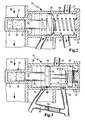
- FIG. 2 shows a sectional view of a control unit 24 when installed.
- the temperature detection unit 27 is mechanical connected to the valve 28.
- the temperature detection unit 27 is characterized by a, partially formed with a temperature-sensitive substance 30 filled bush 31, wherein the bush 31 is made of a material which has a good thermal conductivity having. So that the liquid temperature at the temperature-sensitive Material is passed, the sleeve 31 is in contact with the liquid. is the liquid temperature is cold, the temperature-sensitive substance 30 contracts. At a high liquid temperature, the temperature-sensitive expands Fabric 30 off.
- the valve 28 is characterized by a piston rod 32, a piston 33 and a spring guide 34 formed.
- the piston rod 32 is preferably made cylindrical, it but are also differently formed such. cuboid piston rods 32 conceivable.
- the piston rod 32 is filled with the temperature-sensitive substance 30 Inserted bush 31, whereby it is to be ensured that the piston rod 32 is smooth, however, the temperature-sensitive substance 30 when expanding can not escape between the piston rod 32 and the bush 31.
- the piston rod 32 When stretching of the temperature-sensitive substance 30, the piston rod 32 must at least partially pushed out of the socket 31, it being advantageous when a part of the piston rod 32 remains in the sleeve, whereby the piston rod 32 receives a guide portion 35, which is a tilting of the piston rod 32nd prevented when inserted into the socket 31.
- the piston rod 32 with a spring 36 which between the piston 33 and a shutter 37 is clamped in the socket 31st pressed.
- the spring 36 is in a valve seat with a low bias 38, which together with the closure 37, the outer contour of the control unit 24 forms, so that the temperature-sensitive substance 30, the piston rod 32 can still move.
- the closure 37 may be detachable or unsolvable with the Valve receptacle 38 connected.
- the piston 33 is cylindrical and has a peripheral surface 39, which in the valve seat 38 is guided.
- the piston 33 is so to the valve seat 38th tolerates that no or only a small leakage current can occur.
- the control unit 24 is flowed through by the liquid.
- the liquid passes from the liquid return 21 in the control unit 24. If the liquid temperature is above a defined temperature, then the temperature-sensitive substance 30 is expanded and the piston rod 32 projects far out of the bushing 31, whereby the piston 33 is in an end position, in which the connecting line 29 is closed and the liquid in the Liquid outlet 22 is passed. At a liquid temperature below one defined temperature, the temperature-sensitive substance 30 has contracted and the piston rod 32 protrudes only slightly out of the bush 31. In this switching position (dash-dotted lines shown) is the piston 33 in one second end position in which it releases the connecting line 29 and the liquid thus flow through the liquid outlet 22 and the connecting line 29 can.
- Chokes (not shown) may be provided, which control the flow of the liquid control, depending on where more liquid should flow.
- the liquid return 21 and the liquid outlet 22 may be arranged to be one another are opposite or at an angle to each other.
- the liquid return 21 can also be offset in a plane to the liquid outlet 22 may be arranged.
- the connecting line 29 is arranged such that the piston 33 closes the connecting line at higher liquid temperatures and releases at lower liquid temperatures.
- FIG. 3 shows a control unit 24 in section.
- This control unit 24 corresponds essentially Figure 2, but with the valve 28 and the position of the liquid return 21 and the liquid outlet 22 are modified.
- the location of the Liquid return 21 to the liquid outlet 22 is selected such that a Distance D is in between.
- the valve 28 has a closure piston in this embodiment 40, which is arranged at a distance A to the piston 33.
- the distance A and the distance D are matched to one another such that the Valve 28 in a first end position, the liquid return 21 and the liquid outlet 22 free and the connecting line 29 closes with the piston 28 and in a second end position (shown in phantom) the liquid return 21st and the connecting line 29 releases, but the liquid outlet 22 with the Closure piston 40 closes.
- a pressure relief valve 54 is provided.
- the pressure relief valve 54 is in a Pressure relief line 55, which the connecting line 29 with the liquid outlet 22 connects, arranged.
- a defined fluid pressure in particular 1 bar
- the relief valve 54 shoots again and the Liquid is only passed through the connecting line 29.
- FIG. 4 shows a liquid filter system 12 in a perspective view. which is arranged in particular in a fuel injection system of a V-engine can be.
- the liquid filter system 12 is essentially a housing 18 and a holder 43 is formed.
- the housing 18 has a container 41 and a lid 42, wherein the lid 42 and the container 41 formed mounting portions 44, which are fixed to each other with screws 45.
- the raw liquid inlet 19 and the liquid outlet 22 arranged on the container 41 which as a plug-in part with a press fit are inserted into the container 41 and glued sealing.
- the raw fluid inlet 19 opens into a liquid tube 46, in which a liquid heating 47 is arranged, which the incoming liquid, at a liquid temperature below a defined value.
- the liquid outlet 22 may with the liquid line 16 (not shown) according to Figure 1 with the liquid storage 10 (not shown) are connected.
- This embodiment has two clean fluid outlets 20 and two fluid returns 21, which are integrated in the lid 42 and as plug-in parts are glued sealingly with the lid 42.
- This allows two consumers 14 (not shown) to be connected in parallel.
- To several consumers 14 with the Fluid filter system 12 to connect is a corresponding number of clean fluid outlets 20 and liquid return 21 provided, however, the Performance of the liquid pump 17 (not shown) to be designed accordingly got to.
- This liquid filter system 12 has a water drain plug 48 with which Water or other separated liquid, which is in the container 41st has settled, can be drained from the liquid filter system 12.
- a sensor (not shown) in the lower part of the liquid filter system 12, which senses the separated liquid and with a Signal a draining of the separated liquid automatically or manually causes.
- This sensor (not shown) may be designed such that it additionally, a fluid pressure prevailing in the fluid filter system 12 detected.
- the holder 43 is attached to the liquid tube 46.
- the attachment of the holder 43 is also possible at other locations of the housing 18.
- the holder 43 has two holes 49 through which fastening screws (Not shown) can be inserted through and with the intended elements (not shown) can be screwed, wherein damping components (not shown) such as e.g. Rubber elements can be used.
- damping components such as e.g. Rubber elements can be used.
- Farther can on the container 41 more attachment points (not shown) be provided, which in corresponding receptacles (not shown) using can be inserted by damping components.
- a liquid filter system 12 is shown in section along section line A-A shown in FIG.
- This section A-A runs centrally through the clean fluid outlet 20, the liquid return 21 and the control unit 24, whereby the cover 42, the upper half is missing.
- the control unit 24 is integrated in the lid 42, which is designed such that it has walls 51, which the liquid leads in desired tracks.
- the temperature detection unit 27 is connected to the Liquid on the clean side 26 in contact.
- the piston 34 is in its final position in cold state, wherein it is located in a receptacle 50 which is formed by walls 51 of the lid, and thereby the connecting line 29th releases. This allows the unused and by the liquid return 21st returned liquid in the connecting line 29 and thus on the raw side 25 of the filter element 23 (not shown) arrive. Another part of the liquid is supplied via an outlet 52 to the liquid outlet 22, since this not locked.
- the filter element 23 (not shown) by formed two round filter cartridges, which below two outlets 53 in the container 41 (not shown) are arranged according to Figure 4.
- the piston 33 in its end position in the warm state (shown in phantom). In this position, the piston 33 closes the connecting line, whereby the returned liquid through the outlet 52 to the liquid outlet 22nd is supplied.
Landscapes
- Engineering & Computer Science (AREA)
- Chemical & Material Sciences (AREA)
- Combustion & Propulsion (AREA)
- Mechanical Engineering (AREA)
- General Engineering & Computer Science (AREA)
- Chemical Kinetics & Catalysis (AREA)
- Filtration Of Liquid (AREA)
- Temperature-Responsive Valves (AREA)
- Cookers (AREA)
Description
- Figur 1
- einen Flüssigkeitskreislauf,
- Figur 2
- eine Steuereinheit im eingebauten Zustand im Schnitt,
- Figur 3
- eine Steuereinheit im Schnitt,
- Figur 4
- ein Flüssigkeitsfiltersystem in perspektivischer Ansicht und
- Figur 5
- ein Flüssigkeitsfltersystem im Schnitt.
Claims (10)
- Flüssigkeitskreislauf, insbesondere eine Kraftstoffeinspritzanlage mit einer Kraftstoffrückführung, aufweisend einen Flüssigkeitsspeicher (10), eine Flüssigkeitspumpe (17), einen Verbraucher (14), ein Filterelement (23) mit einer Rohseite (25) und einer Reinseite (26) und eine Steuereinheit (24), wobei die Steuereinheit (24) eine Temperaturerfassungseinheit (27) zur Ermittlung einer Flüssigkeitstemperatur einer Flüssigkeit in dem Flüssigkeitskreislauf aufweist, wobei mit der Flüssigkeitstemperatur ein, in der Steuereinheit (24) enthaltenes Ventil (28) steuerbar ist, wodurch die, durch den Verbraucher (14) nicht entnommene, Flüssigkeit zumindest teilweise dem Filterelement (23) wieder zuführbar ist, wobei
das Filterelement (23) und die Steuereinheit (24) in ein Flüssigkeitsfiltersystem (12) integriert sind, welches durch ein Gehäuse (18) gebildet ist und über einen Rohflüssigkeitseinlass (19), einen Reinflüssigkeitsauslass (20), einen Flüssigkeitsrücklauf (21) und einen Flüssigkeitsauslass (22) verfügt, wobeider gehäusefeste Rohflüssigkeüseinlass (19), welcher korrespondierend mit der Rohseite (25) des Filterelementes (23) verbunden ist, über eine Rohflüssigkeitsleitung (11) mit dem Flüssigkeitsspeicher (10) verbunden ist,der gehäusefeste Reinflüssigkeitsauslass (20), welcher korrespondierend mit der Reinseite (26) des Filterelementes (23) verbunden ist, über eine Reinflüssigkeitsleitung (13) mit dem Verbraucher (14) verbunden ist,der gehäusefeste Flüssigkeitsrücklauf (21), welcher korrespondierend mit der Steuereinheit (24) verbunden ist und über eine Flüssigkeitsrückleitung (15) mit dem Verbraucher (14) verbunden ist, undder gehäusefeste Flüssigkeitsauslass (22), welcher korrespondierend mit der Steuereinheit (24) verbunden ist, über eine Flüssigkeitsableitung (16) mit dem Flüssigkeitsspeicher (10) verbunden ist, undwobei die Steuereinheit (24) über eine Verbindungsleitung (29) mit der Rohseite (25) des Filterelementes (23) verbunden ist, dadurch gekennzeichnet, dasswobei die Temperaturerfassungseinheit (27) flussabwärts zwischen dem Flüssigkeitsspeicher (10) und dem Verbraucher (14), insbesondere auf der Rohseite (25), der Reinseite (26) des Filterelementes oder in den Flüssigkeitsleitungen (11, 13), angeordnet ist. - Flüssigkeitskreislauf nach Anspruch 1, dadurch gekennzeichnet, dass das Gehäuse (18) zweiteilig ausgeführt ist und einen Behälter (41) und einen Deckel (42) aufweist, wobei die Steuereinheit (24) in dem Deckel (42) und das Filterelement (23) in dem Behälter (41) angeordnet ist.
- Flüssigkeitskreislauf nach einem der Ansprüche 1 oder 2, dadurch gekennzeichnet, dass die Temperaturerfassungseinheit (27) mit dem Ventil (28) mechanisch verbunden ist.
- Flüssigkeitskreislauf nach einem der vorangehenden Ansprüche, dadurch gekennzeichnet, dass in dem Flüssigkeitsfiltersystem (12) eine Entlüftungsvorrichtung angeordnet ist.
- Flüssigkeitskreislauf nach einem der vorangehenden Ansprüche, dadurch gekennzeichnet, dass eine Vorrichtung zur Entfernung einer abgeschiedenen Zweiflüssigkeit, insbesondere eine Wasserablassschraube (48), in dem Flüssigkeitsfiltersystem (12) vorgesehen ist.
- Flüssigkeitskreislauf nach einem der vorangehenden Ansprüche, dadurch gekennzeichnet, dass eine Flüssigkeitsheizung (47) in das Flüssigkeitsfiltersystem (12) integriert ist.
- Flüssigkeitskreislauf nach einem der vorangehenden Ansprüchen, dadurch gekennzeichnet, dass der Steuereinheit (24) eine Rücklaufsperre , insbesondere ein Rücklaufsperrventil, nachgeordnet ist.
- Flüssigkeitskreislauf nach einem der vorangehenden Ansprüchen, dadurch gekennzeichnet, dass in dem Flüssigkeitsfiltersystem (12) ein Überdruckventil (54) angeordnet ist, welches insbesondere der Steuereinheit (24) nachgeordnet ist.
- Flüssigkeitskreislauf nach einem der vorangehenden Ansprüche, dadurch gekennzeichnet, dass der Deckel (42) mit Schrauben (45) auf dem Behälter (41) flüssigkeitsdicht befestigt ist.
- Flüssigkeitskreislauf nach einem der vorangehenden Ansprüche, dadurch gekennzeichnet, dass das Flüssigkeitsfiltersystem (12) in einer Kräftstoffeinspritzanlage einer dieselbetriebenen Brennkraftmaschine eingebracht ist.
Applications Claiming Priority (3)
| Application Number | Priority Date | Filing Date | Title |
|---|---|---|---|
| DE10030324A DE10030324A1 (de) | 2000-06-27 | 2000-06-27 | Flüssigkeitskreislauf |
| DE10030324 | 2000-06-27 | ||
| PCT/EP2001/006548 WO2002001061A1 (de) | 2000-06-27 | 2001-06-09 | Flüssigkeitskreislauf |
Publications (2)
| Publication Number | Publication Date |
|---|---|
| EP1295025A1 EP1295025A1 (de) | 2003-03-26 |
| EP1295025B1 true EP1295025B1 (de) | 2005-10-12 |
Family
ID=7646359
Family Applications (1)
| Application Number | Title | Priority Date | Filing Date |
|---|---|---|---|
| EP01960294A Expired - Lifetime EP1295025B1 (de) | 2000-06-27 | 2001-06-09 | Flüssigkeitskreislauf |
Country Status (6)
| Country | Link |
|---|---|
| US (2) | US7192518B2 (de) |
| EP (1) | EP1295025B1 (de) |
| AT (1) | ATE306612T1 (de) |
| DE (2) | DE10030324A1 (de) |
| ES (1) | ES2249467T3 (de) |
| WO (1) | WO2002001061A1 (de) |
Families Citing this family (28)
| Publication number | Priority date | Publication date | Assignee | Title |
|---|---|---|---|---|
| GB0205965D0 (en) | 2002-03-14 | 2002-04-24 | Delphi Tech Inc | Fuel system |
| DE10261690A1 (de) * | 2002-12-31 | 2004-07-15 | Robert Bosch Gmbh | Hochleistungs-Kraftstofffilter |
| KR100580459B1 (ko) * | 2003-11-04 | 2006-05-15 | 현대자동차주식회사 | 연료압력 손실 저감을 위한 디젤 엔진 차량의 연료공급시스템 |
| FR2879674B1 (fr) * | 2004-12-20 | 2007-03-30 | Filtrauto Sa | Systeme de filtration a gazole |
| JP4347271B2 (ja) | 2005-07-06 | 2009-10-21 | 京三電機株式会社 | リターン環流バルブ |
| DE202005019318U1 (de) * | 2005-12-08 | 2007-04-19 | Mann + Hummel Gmbh | Regelmodul zur Mischung von Fluiden |
| WO2008000462A1 (de) * | 2006-06-27 | 2008-01-03 | Georg Gruber | Dieselmotorisch betriebene brennkraftmaschine |
| DE102006060885A1 (de) * | 2006-12-22 | 2008-06-26 | Volkswagen Ag | Kraftstoff-Vorwärmvorrichtung |
| US7926470B2 (en) * | 2008-04-11 | 2011-04-19 | Caterpillar Inc. | Compact relief valve having damping functionality |
| DE202008010505U1 (de) * | 2008-08-07 | 2009-12-10 | Mann + Hummel Gmbh | Kraftstofffilter eines Verbrennungsmotors |
| US7827971B2 (en) * | 2009-01-26 | 2010-11-09 | Gm Global Technology Operations, Inc. | Engine assembly with fuel filter gas removal apparatus |
| DE102009030500B4 (de) | 2009-06-24 | 2012-03-01 | Mann + Hummel Gmbh | Flüssigkeitsfiltersystem eines Flüssigkeitskreislaufs |
| US8186332B2 (en) * | 2009-07-20 | 2012-05-29 | Mann & Hummel Gmbh | Fluid filter with integrated temperature regulation |
| CA2826891C (en) | 2011-02-09 | 2018-01-02 | Allison Transmission, Inc. | Scavenge pump oil level control system and method |
| CN103402841B (zh) | 2011-02-17 | 2016-04-27 | 艾里逊变速箱公司 | 用于混合动力车辆的液压系统和方法 |
| CN103459223B (zh) * | 2011-03-11 | 2017-05-24 | 艾里逊变速箱公司 | 堵塞的过滤器的检测系统和方法 |
| WO2012177815A1 (en) | 2011-06-22 | 2012-12-27 | Allison Transmission, Inc. | Low level oil detection system and method |
| DE102011085993A1 (de) * | 2011-11-09 | 2013-05-16 | Mahle International Gmbh | Ventileinsatz und zugehörige Filtereinrichtung |
| CA2860546C (en) * | 2012-01-10 | 2018-12-04 | C.C. Jensen A/S | Method and system for cleaning degraded oil |
| US9051906B2 (en) * | 2012-02-29 | 2015-06-09 | Ford Global Technologies, Llc | Diesel fuel system conditioning |
| DE102012010718A1 (de) * | 2012-05-30 | 2013-12-05 | Robert Bosch Gmbh | Filtervorrichtung und Verfahren zurHerstellung einer Filtervorrichtung |
| DE102013210973A1 (de) * | 2013-06-12 | 2014-12-18 | Mahle International Gmbh | Kraftstoffversorgungssystem |
| US20160186706A1 (en) * | 2014-07-15 | 2016-06-30 | Brazil Green Energy Technologies, Llc | Systems and methods for fuel state control with fuel recirculation and preheat |
| ES2673611T3 (es) * | 2016-02-16 | 2018-06-25 | Willibrord Lösing Filterproduktion Gmbh | Dispositivo para la limpieza de un elemento líquido |
| CN106151477A (zh) * | 2016-08-17 | 2016-11-23 | 无锡市鑫盛换热器制造有限公司 | 齿轮箱润滑冷却系统及其工作方法 |
| DE102016222778A1 (de) * | 2016-11-18 | 2018-05-24 | Siemens Aktiengesellschaft | Verfahren zum Entwässern eines Betriebsstoffs, Entwässerungseinrichtung sowie Betriebsstoff-Versorgungseinrichtung |
| DE102017007603A1 (de) | 2017-08-11 | 2019-02-14 | Hydac Fluidcarecenter Gmbh | Fördervorrichtung für den Kraftstoff einer Verbrennungs-Kraftmaschine |
| US12409264B2 (en) | 2023-10-16 | 2025-09-09 | Mark Louis Venturi | Adipose tissue separation device with pressure equalization |
Family Cites Families (12)
| Publication number | Priority date | Publication date | Assignee | Title |
|---|---|---|---|---|
| JPS58113573A (ja) * | 1981-12-28 | 1983-07-06 | フオ−ド・モ−タ−・カンパニ− | 加熱燃料噴射装置 |
| US4502451A (en) * | 1982-08-25 | 1985-03-05 | Standard-Thomson Corporation | Diesel fuel control apparatus and system |
| GB2245651A (en) * | 1990-07-04 | 1992-01-08 | Ford Motor Co | I.c.engine fuel feed arrangement |
| DE4420043C1 (de) * | 1994-06-08 | 1995-09-14 | Kraft Herbert Georgsdorf | Kraftstoffeinspritzanlage für Dieselmotoren mit Kraftstofferwärmung für den Winterbetrieb |
| FR2751242B1 (fr) * | 1996-07-18 | 1998-09-25 | Filtrauto | Filtre a gazole pour moteur diesel et dispositif d'alimentation incluant un tel filtre |
| EP0833050A1 (de) * | 1996-09-28 | 1998-04-01 | Lucas Industries Public Limited Company | Brennstoff-Filtersystem |
| DE19714488C1 (de) * | 1997-04-08 | 1998-09-03 | Siemens Ag | Verfahren zum Erwärmen von Kraftstoff und Kraftstoffeinspritzanlage |
| US5887573A (en) * | 1997-06-25 | 1999-03-30 | Stanadyne Automotive Corp. | Fuel filter with cold start circuit |
| FR2782750B1 (fr) * | 1998-09-01 | 2000-10-20 | Filtrauto | Dispositif d'alimentation en gazole pour moteur diesel, et filtre pour un tel dispositif |
| US6189513B1 (en) * | 1999-06-03 | 2001-02-20 | Ford Global Technologies, Inc. | Fuel transfer and conditioning unit for automotive vehicle |
| DE19926172B4 (de) * | 1999-06-09 | 2019-12-19 | Robert Bosch Gmbh | Filter für Dieselkraftstoff |
| US6361684B1 (en) * | 2000-05-10 | 2002-03-26 | Fleetguard, Inc. | Integrated fuel pump and fuel filter with fuel-water separation |
-
2000
- 2000-06-27 DE DE10030324A patent/DE10030324A1/de not_active Withdrawn
-
2001
- 2001-06-09 EP EP01960294A patent/EP1295025B1/de not_active Expired - Lifetime
- 2001-06-09 WO PCT/EP2001/006548 patent/WO2002001061A1/de not_active Ceased
- 2001-06-09 ES ES01960294T patent/ES2249467T3/es not_active Expired - Lifetime
- 2001-06-09 DE DE50107696T patent/DE50107696D1/de not_active Expired - Lifetime
- 2001-06-09 AT AT01960294T patent/ATE306612T1/de not_active IP Right Cessation
-
2002
- 2002-12-26 US US10/328,173 patent/US7192518B2/en not_active Expired - Lifetime
-
2007
- 2007-03-16 US US11/723,164 patent/US20070175807A1/en not_active Abandoned
Also Published As
| Publication number | Publication date |
|---|---|
| US20030150783A1 (en) | 2003-08-14 |
| US7192518B2 (en) | 2007-03-20 |
| DE10030324A1 (de) | 2002-01-10 |
| ATE306612T1 (de) | 2005-10-15 |
| DE50107696D1 (de) | 2006-02-23 |
| US20070175807A1 (en) | 2007-08-02 |
| ES2249467T3 (es) | 2006-04-01 |
| WO2002001061A1 (de) | 2002-01-03 |
| EP1295025A1 (de) | 2003-03-26 |
Similar Documents
| Publication | Publication Date | Title |
|---|---|---|
| EP1295025B1 (de) | Flüssigkeitskreislauf | |
| DE60019490T2 (de) | Brennstofförder-und behandlungsvorrichtung | |
| DE60122707T2 (de) | Kraftstoffilteranordnung mit ansaugpumpe und heizvorrichtung | |
| DE3226508C2 (de) | Kühlkreis für Brennkraftmaschinen | |
| DE3101574C2 (de) | Vorrichtung zum Filtern und Kühlen des Schmiermittels einer Brennkraftmaschine | |
| EP0295445B1 (de) | Flüssigkeits-Kühlkreis für Kraft- und Arbeitsmaschinen, insbesondere Brennkraftmaschinen | |
| DE69901411T2 (de) | Flüssigkeitsbehälter und Kühler eines Servolenkungssystems | |
| DE102008008466B4 (de) | Fluidspeichervorrichtung und damit aususgestaltetes Getriebe | |
| EP1403475A1 (de) | Flüssigkeitsfilter-Wärmetauscher-Einheit | |
| DE19847999A1 (de) | Filtereinrichtung | |
| EP0009564A1 (de) | Schmierölkreislauf für eine Brennkraftmaschine | |
| EP1198682B1 (de) | Schnellkupplung für das öffnen eines ventils | |
| DE102015002767A1 (de) | Filtervorrichtung | |
| DE102004024466A1 (de) | Kraftstoffmodul | |
| DE69100220T2 (de) | Verfahren und Vorrichtung zum Filtrieren einer Flüssigkeit. | |
| EP1130224A1 (de) | Flüssigkeitsfilter mit einem Kühler | |
| EP1067999B9 (de) | Flüssigkeitsfilter | |
| EP1855778A1 (de) | Flüssigkeitsfilter-wärmetauscher-einheit | |
| DE102007039232A1 (de) | Brennstoffpumpenmodul für ein elektronisches rückführloses Brennstoffsystem | |
| DE102009030500B4 (de) | Flüssigkeitsfiltersystem eines Flüssigkeitskreislaufs | |
| WO2018188950A1 (de) | Wassertankeinrichtung für eine brennkraftmaschine mit wassereinspritzung | |
| EP2532848B1 (de) | Filter- und Kühlvorrichtung | |
| DE102012218235B4 (de) | Ölreservoir mit Umlenkblech | |
| DE69718801T2 (de) | Filter- und kühlvorrichtung | |
| EP0071053B1 (de) | Brennstoffvorwärmverfahren für Brennkraftmaschinen für Schwerölbetrieb und Brennstoffsystem hierfür |
Legal Events
| Date | Code | Title | Description |
|---|---|---|---|
| PUAI | Public reference made under article 153(3) epc to a published international application that has entered the european phase |
Free format text: ORIGINAL CODE: 0009012 |
|
| 17P | Request for examination filed |
Effective date: 20021121 |
|
| AK | Designated contracting states |
Designated state(s): AT BE CH CY DE DK ES FI FR GB GR IE IT LI LU MC NL PT SE TR Kind code of ref document: A1 Designated state(s): AT BE CH CY DE DK ES FI FR GB GR IE IT LI LU MC NL PT SE TR |
|
| RAP1 | Party data changed (applicant data changed or rights of an application transferred) |
Owner name: MANN + HUMMEL GMBH |
|
| GRAP | Despatch of communication of intention to grant a patent |
Free format text: ORIGINAL CODE: EPIDOSNIGR1 |
|
| GRAS | Grant fee paid |
Free format text: ORIGINAL CODE: EPIDOSNIGR3 |
|
| GRAA | (expected) grant |
Free format text: ORIGINAL CODE: 0009210 |
|
| AK | Designated contracting states |
Kind code of ref document: B1 Designated state(s): AT BE CH CY DE DK ES FI FR GB GR IE IT LI LU MC NL PT SE TR |
|
| PG25 | Lapsed in a contracting state [announced via postgrant information from national office to epo] |
Ref country code: FI Free format text: LAPSE BECAUSE OF FAILURE TO SUBMIT A TRANSLATION OF THE DESCRIPTION OR TO PAY THE FEE WITHIN THE PRESCRIBED TIME-LIMIT Effective date: 20051012 Ref country code: NL Free format text: LAPSE BECAUSE OF FAILURE TO SUBMIT A TRANSLATION OF THE DESCRIPTION OR TO PAY THE FEE WITHIN THE PRESCRIBED TIME-LIMIT Effective date: 20051012 Ref country code: IE Free format text: LAPSE BECAUSE OF FAILURE TO SUBMIT A TRANSLATION OF THE DESCRIPTION OR TO PAY THE FEE WITHIN THE PRESCRIBED TIME-LIMIT Effective date: 20051012 |
|
| REG | Reference to a national code |
Ref country code: GB Ref legal event code: FG4D Free format text: NOT ENGLISH |
|
| REG | Reference to a national code |
Ref country code: CH Ref legal event code: EP |
|
| REG | Reference to a national code |
Ref country code: IE Ref legal event code: FG4D Free format text: LANGUAGE OF EP DOCUMENT: GERMAN |
|
| PG25 | Lapsed in a contracting state [announced via postgrant information from national office to epo] |
Ref country code: DK Free format text: LAPSE BECAUSE OF FAILURE TO SUBMIT A TRANSLATION OF THE DESCRIPTION OR TO PAY THE FEE WITHIN THE PRESCRIBED TIME-LIMIT Effective date: 20060112 Ref country code: SE Free format text: LAPSE BECAUSE OF FAILURE TO SUBMIT A TRANSLATION OF THE DESCRIPTION OR TO PAY THE FEE WITHIN THE PRESCRIBED TIME-LIMIT Effective date: 20060112 Ref country code: GR Free format text: LAPSE BECAUSE OF FAILURE TO SUBMIT A TRANSLATION OF THE DESCRIPTION OR TO PAY THE FEE WITHIN THE PRESCRIBED TIME-LIMIT Effective date: 20060112 |
|
| GBT | Gb: translation of ep patent filed (gb section 77(6)(a)/1977) |
Effective date: 20060105 |
|
| REF | Corresponds to: |
Ref document number: 50107696 Country of ref document: DE Date of ref document: 20060223 Kind code of ref document: P |
|
| PG25 | Lapsed in a contracting state [announced via postgrant information from national office to epo] |
Ref country code: PT Free format text: LAPSE BECAUSE OF FAILURE TO SUBMIT A TRANSLATION OF THE DESCRIPTION OR TO PAY THE FEE WITHIN THE PRESCRIBED TIME-LIMIT Effective date: 20060313 |
|
| REG | Reference to a national code |
Ref country code: ES Ref legal event code: FG2A Ref document number: 2249467 Country of ref document: ES Kind code of ref document: T3 |
|
| NLV1 | Nl: lapsed or annulled due to failure to fulfill the requirements of art. 29p and 29m of the patents act | ||
| ET | Fr: translation filed | ||
| REG | Reference to a national code |
Ref country code: IE Ref legal event code: FD4D |
|
| PG25 | Lapsed in a contracting state [announced via postgrant information from national office to epo] |
Ref country code: LI Free format text: LAPSE BECAUSE OF NON-PAYMENT OF DUE FEES Effective date: 20060630 Ref country code: CH Free format text: LAPSE BECAUSE OF NON-PAYMENT OF DUE FEES Effective date: 20060630 Ref country code: BE Free format text: LAPSE BECAUSE OF NON-PAYMENT OF DUE FEES Effective date: 20060630 Ref country code: MC Free format text: LAPSE BECAUSE OF NON-PAYMENT OF DUE FEES Effective date: 20060630 |
|
| PLBE | No opposition filed within time limit |
Free format text: ORIGINAL CODE: 0009261 |
|
| STAA | Information on the status of an ep patent application or granted ep patent |
Free format text: STATUS: NO OPPOSITION FILED WITHIN TIME LIMIT |
|
| 26N | No opposition filed |
Effective date: 20060713 |
|
| REG | Reference to a national code |
Ref country code: CH Ref legal event code: PL |
|
| PG25 | Lapsed in a contracting state [announced via postgrant information from national office to epo] |
Ref country code: AT Free format text: LAPSE BECAUSE OF NON-PAYMENT OF DUE FEES Effective date: 20060609 |
|
| BERE | Be: lapsed |
Owner name: MANN + HUMMEL G.M.B.H. Effective date: 20060630 |
|
| PG25 | Lapsed in a contracting state [announced via postgrant information from national office to epo] |
Ref country code: LU Free format text: LAPSE BECAUSE OF NON-PAYMENT OF DUE FEES Effective date: 20060609 Ref country code: TR Free format text: LAPSE BECAUSE OF FAILURE TO SUBMIT A TRANSLATION OF THE DESCRIPTION OR TO PAY THE FEE WITHIN THE PRESCRIBED TIME-LIMIT Effective date: 20051012 |
|
| PG25 | Lapsed in a contracting state [announced via postgrant information from national office to epo] |
Ref country code: CY Free format text: LAPSE BECAUSE OF FAILURE TO SUBMIT A TRANSLATION OF THE DESCRIPTION OR TO PAY THE FEE WITHIN THE PRESCRIBED TIME-LIMIT Effective date: 20051012 |
|
| REG | Reference to a national code |
Ref country code: FR Ref legal event code: PLFP Year of fee payment: 16 |
|
| REG | Reference to a national code |
Ref country code: FR Ref legal event code: PLFP Year of fee payment: 17 |
|
| REG | Reference to a national code |
Ref country code: FR Ref legal event code: PLFP Year of fee payment: 18 |
|
| REG | Reference to a national code |
Ref country code: DE Ref legal event code: R081 Ref document number: 50107696 Country of ref document: DE Owner name: MANN+HUMMEL GMBH, DE Free format text: FORMER OWNER: MANN + HUMMEL GMBH, 71638 LUDWIGSBURG, DE |
|
| PGFP | Annual fee paid to national office [announced via postgrant information from national office to epo] |
Ref country code: DE Payment date: 20200618 Year of fee payment: 20 Ref country code: FR Payment date: 20200619 Year of fee payment: 20 |
|
| PGFP | Annual fee paid to national office [announced via postgrant information from national office to epo] |
Ref country code: GB Payment date: 20200625 Year of fee payment: 20 |
|
| PGFP | Annual fee paid to national office [announced via postgrant information from national office to epo] |
Ref country code: ES Payment date: 20200824 Year of fee payment: 20 |
|
| PGFP | Annual fee paid to national office [announced via postgrant information from national office to epo] |
Ref country code: IT Payment date: 20200625 Year of fee payment: 20 |
|
| REG | Reference to a national code |
Ref country code: DE Ref legal event code: R071 Ref document number: 50107696 Country of ref document: DE |
|
| REG | Reference to a national code |
Ref country code: GB Ref legal event code: PE20 Expiry date: 20210608 |
|
| PG25 | Lapsed in a contracting state [announced via postgrant information from national office to epo] |
Ref country code: GB Free format text: LAPSE BECAUSE OF EXPIRATION OF PROTECTION Effective date: 20210608 |
|
| REG | Reference to a national code |
Ref country code: ES Ref legal event code: FD2A Effective date: 20220128 |
|
| PG25 | Lapsed in a contracting state [announced via postgrant information from national office to epo] |
Ref country code: ES Free format text: LAPSE BECAUSE OF EXPIRATION OF PROTECTION Effective date: 20210610 |