EP1295363B1 - Connecteur pour transmission d'un signal a haute vitesse - Google Patents
Connecteur pour transmission d'un signal a haute vitesse Download PDFInfo
- Publication number
- EP1295363B1 EP1295363B1 EP01950373A EP01950373A EP1295363B1 EP 1295363 B1 EP1295363 B1 EP 1295363B1 EP 01950373 A EP01950373 A EP 01950373A EP 01950373 A EP01950373 A EP 01950373A EP 1295363 B1 EP1295363 B1 EP 1295363B1
- Authority
- EP
- European Patent Office
- Prior art keywords
- contact
- connector
- shield
- forwardly extending
- contacts
- Prior art date
- Legal status (The legal status is an assumption and is not a legal conclusion. Google has not performed a legal analysis and makes no representation as to the accuracy of the status listed.)
- Expired - Lifetime
Links
- 238000003780 insertion Methods 0.000 claims abstract description 14
- 230000037431 insertion Effects 0.000 claims abstract description 14
- 230000013011 mating Effects 0.000 claims abstract description 11
- 239000012212 insulator Substances 0.000 claims description 7
- 239000004020 conductor Substances 0.000 description 4
- 229920000106 Liquid crystal polymer Polymers 0.000 description 3
- 229920013651 Zenite Polymers 0.000 description 3
- 239000011521 glass Substances 0.000 description 3
- PGNWIWKMXVDXHP-UHFFFAOYSA-L zinc;1,3-benzothiazole-2-thiolate Chemical compound [Zn+2].C1=CC=C2SC([S-])=NC2=C1.C1=CC=C2SC([S-])=NC2=C1 PGNWIWKMXVDXHP-UHFFFAOYSA-L 0.000 description 3
- 230000005540 biological transmission Effects 0.000 description 2
- 238000009413 insulation Methods 0.000 description 2
- 238000000034 method Methods 0.000 description 2
- 229910000906 Bronze Inorganic materials 0.000 description 1
- 229910000881 Cu alloy Inorganic materials 0.000 description 1
- OAICVXFJPJFONN-UHFFFAOYSA-N Phosphorus Chemical compound [P] OAICVXFJPJFONN-UHFFFAOYSA-N 0.000 description 1
- 239000010974 bronze Substances 0.000 description 1
- 230000015556 catabolic process Effects 0.000 description 1
- KUNSUQLRTQLHQQ-UHFFFAOYSA-N copper tin Chemical compound [Cu].[Sn] KUNSUQLRTQLHQQ-UHFFFAOYSA-N 0.000 description 1
- 238000006731 degradation reaction Methods 0.000 description 1
- 230000001419 dependent effect Effects 0.000 description 1
- 238000004519 manufacturing process Methods 0.000 description 1
- 239000000463 material Substances 0.000 description 1
- 238000012986 modification Methods 0.000 description 1
- 230000004048 modification Effects 0.000 description 1
Images




Classifications
-
- H—ELECTRICITY
- H01—ELECTRIC ELEMENTS
- H01R—ELECTRICALLY-CONDUCTIVE CONNECTIONS; STRUCTURAL ASSOCIATIONS OF A PLURALITY OF MUTUALLY-INSULATED ELECTRICAL CONNECTING ELEMENTS; COUPLING DEVICES; CURRENT COLLECTORS
- H01R13/00—Details of coupling devices of the kinds covered by groups H01R12/70 or H01R24/00 - H01R33/00
- H01R13/648—Protective earth or shield arrangements on coupling devices, e.g. anti-static shielding
- H01R13/658—High frequency shielding arrangements, e.g. against EMI [Electro-Magnetic Interference] or EMP [Electro-Magnetic Pulse]
- H01R13/6581—Shield structure
- H01R13/6585—Shielding material individually surrounding or interposed between mutually spaced contacts
-
- H—ELECTRICITY
- H01—ELECTRIC ELEMENTS
- H01R—ELECTRICALLY-CONDUCTIVE CONNECTIONS; STRUCTURAL ASSOCIATIONS OF A PLURALITY OF MUTUALLY-INSULATED ELECTRICAL CONNECTING ELEMENTS; COUPLING DEVICES; CURRENT COLLECTORS
- H01R13/00—Details of coupling devices of the kinds covered by groups H01R12/70 or H01R24/00 - H01R33/00
- H01R13/648—Protective earth or shield arrangements on coupling devices, e.g. anti-static shielding
Definitions
- This invention relates to two-part electrical connectors, and particularly to improvements in shielded two-part high-speed electrical connectors.
- Conductors carrying high frequency signals and currents are subject to interference and cross talk when placed in close proximity to other conductors carrying high frequency signals and currents. This interference and cross talk can result in signal degradation and errors in signal reception.
- Coaxial and shielded cables are available to carry signals from a transmission point to a reception point, and reduce the likelihood that the signal carried in one shielded or coaxial cable will interfere with the signal carried by another shielded or coaxial cable in close proximity.
- the shielding is often lost allowing interference and crosstalk between signals.
- the use of individual shielded wires and cables is not desirable at points of connections due to the need for making a large number of connections in a very small space. In these circumstances, two-part high-speed connectors containing multiple shielded conductive paths are used.
- U.S.-A-6,146,202 discloses an illustrative shielded two-part high-speed connector comprising a socket connector and a header connector.
- the illustrative socket connector includes a plurality of connector modules.
- Each connector module includes an insulative housing encasing a plurality of longitudinally extending, vertically spaced signal contacts arranged in a column.
- Each insulative housing is formed to include a plurality of laterally extending, vertically spaced openings which are interleaved with the plurality of longitudinally extending, vertically spaced signal contacts.
- the socket connector further includes a plurality of vertical shields extending along the first sides of the plurality of connector modules, and a plurality of horizontal shields extending through the laterally extending, vertically spaced openings in the plurality of connector modules to form a coaxial shield around each signal contact.
- an illustrative connector includes a plurality of connector modules.
- Each connector module includes an insulative housing encasing a plurality of longitudinally extending, laterally spaced signal
- a connector comprising a plurality of horizontally spaced contacts arranged in a row. Each contact has a forwardly extending contact portion configured to engage a corresponding contact in a mating connector, an intermediate portion, and a rearwardly extending tail portion.
- An insulative housing is over the intermediate portions of the contacts and has horizontally spaced, vertical slots positioned between the contact intermediate portions, each slot extending in the direction of the adjacent contact.
- a shield is provided having a vertical flange portion for insertion into a vertical slot in the insulative housing and an upper horizontal portion extending along and above the intermediate portion of the adjacent contact.
- the present invention provides a connector as defined in claim 1 and a connector arrangement as defined in claim 8.
- the subject matter of the dependent claims refers to individual embodiments of the invention.
- an illustrative connector includes a plurality of connector modules.
- Each connector module includes an insulative housing encasing a plurality of longitudinally extending, laterally spaced signal contacts arranged in a row.
- Each insulative housing is formed to include a plurality of vertically extending, laterally spaced openings which are interleaved with the plurality of longitudinally extending, laterally spaced signal contacts.
- the connector further includes a plurality of shields.
- Each shield has a vertically extending flange portion for insertion into a vertically extending opening in the insulative housing and a laterally extending flange portion extending along and adjacent to a signal contact in the insulative housing.
- the vertically and laterally extending flange portions are configured to form a coaxial shield around each signal contact.
- the laterally extending flange portion extends along and above an adjacent signal contact in the insulative housing.
- the insulative housings with contacts and shields assembled therein are configured for insertion into laterally extending, vertically spaced slots in a connector housing.
- an illustrative connector includes a plurality of longitudinally extending, laterally spaced signal contacts arranged in a row. Each signal contact includes a forwardly extending contact portion configured to engage a corresponding contact in a mating connector, an intermediate portion and a rearwardly extending tail portion.
- An insulative housing encases the intermediate portions of the signal contacts. The insulative housing includes laterally spaced, vertically extending slots between the contact intermediate portions.
- a shield is provided for each signal contact. Each shield has a vertically extending flange portion for insertion into a slot in the insulative housing and an upper laterally extending flange portion extending along and above the intermediate portion of an adjacent signal contact. The vertically and laterally extending flange portions form a coaxial shield around each signal contact.
- the insulative housings with contacts and shields assembled therein form connector modules which are configured for insertion into a connector housing.
- an illustrative connector includes a plurality of horizontally spaced signal contacts arranged in a row. Each signal contact includes a forwardly extending contact portion configured to engage a corresponding contact in a mating connector, an intermediate portion and a rearwardly extending tail portion.
- An insulative housing encases the intermediate portions of the signal contacts. The insulative housing includes horizontally spaced, vertically extending slots between the contact intermediate portions.
- a shield is provided for each signal contact. Each shield has a vertical flange portion for insertion into a slot in the insulative housing and an upper horizontal flange portion extending along and above the intermediate portion of an adjacent signal contact. The vertical and horizontal flange portions form a coaxial shield around each signal contact.
- the insulative housings with contacts and shields assembled therein form connector modules which are configured for insertion into a connector housing.
- the connector modules may be pressed into single row insulators with a press-fit connection, with one single row insulator for each connector module.
- the assembled connector modules may then be stacked to a desired height, and inserted into a housing.
- the housing captures the assembled connector modules, and provides insulation and shielding around the stacked assembly.
- Fig. 1 shows four horizontally spaced, signal contacts 30 arranged in a row.
- the contacts 30 are arranged in rows instead of columns.
- the horizontal spacing between the adjacent contacts 30 is 2 millimeters.
- Each contact 30 includes a forwardly extending contact portion 32 configured to engage a corresponding signal pin of a mating header connector (not shown), an intermediate portion 34 and a rearwardly extending tail portion 36.
- Each contact portion 32 includes a pair of opposed cantilevered spring arms 38 into which a signal pin of a mating header connector is inserted when a socket connector 20 and a header connector are mated.
- the tail portions 36 are soldered to cable wires.
- the contacts 30 are stamped out of a strip of suitable conductive material, and are manufactured reel to reel. The strip can be cut to any length to create variable connector lengths (e.g., eight signal contacts to a row instead of four to a row).
- an insulative housing 50 encases the contact intermediate portions 34.
- the insulative housing 50 includes four horizontally spaced, vertically extending slots 52 arranged between the contact intermediate portions 34 for receiving four shields 60 - one shield 60 for each contact 30.
- the housing 50 (sometimes referred to herein as the "contact overmold") is formed by overmolding a plastic insulator over the contact intermediate portions 34. The overmolding process can be also performed reel to reel as the contacts 30 are fed on a strip.
- the vertical slots 52 are formed simultaneously between adjacent contacts 30 as the insulative housing 50 is overmolded over the contacts 30.
- a jog is provided in the tail portion 36 to center the tail portion 26 in the plastic overmold 50 during the overmolding operation.
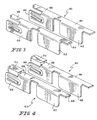
- Fig. 3 shows two horizontally spaced apart shields 60.
- the horizontal spacing between the adjacent shields 60 is 4 millimeters.
- the shields 60 are stamped out of a strip of suitable conductive material, and are manufactured reel to reel.
- the 4 millimeter spacing between the shields 60 makes it possible to manufacture the shields 60 reel to reel.
- Each shield 60 includes a vertical flange portion 62 for insertion into a slot 52 in the insulative housing 50, and an upper horizontal portion 64 extending along and above the intermediate portion 34 of the adjacent contact 30.
- the vertical flange portion 62 of each shield 60 includes a forwardly extending vertical shield portion 66 configured to be located next to a forwardly extending contact portion 32 of an adjacent contact 30.
- the forwardly extending vertical shield portion 66 is configured to engage a ground pin of a mating header connector (not shown) to couple the shield 60 to ground.
- the upper horizontal portion 64 of each shield 60 includes a forwardly extending horizontal shield portion 68 configured to be located above a forwardly extending contact portion 32 of an adjacent contact 30. As shown in Fig. 12, the vertical flange portion 62 provides shielding between adjacent columns of contacts 30. The upper horizontal portion 64 provides shielding between adjacent rows of contacts 30.
- the forwardly extending horizontal shield portion 68 of each shield 60 includes an insulative housing 70 surrounding the forwardly extending horizontal shield portion 68.
- the insulative housing 70 (sometimes referred to herein as the "shield overmold") may be formed by overmolding a plastic insulator over the forwardly extending horizontal shield portion 68 of the upper horizontal portion 64. The ovennolding process can also be performed reel to reel as the shields 60 are fed on a strip.
- the plastic overmold 70 prevents the vertically compliant spring arms 38 from accidently contacting the forwardly extending horizontal shield portion 68 when a signal pin of the header connector (not shown) is inserted between the vertically compliant spring arms 38 as the socket connector 20 is mated with a header connector (not shown).
- Fig. 5 shows a first set of shields 60 vertically aligned with first and third slots 52 in the contact overmold 50 having contacts 30 embedded therein.
- Fig. 6 shows the first set of shields 60 pressed into the first and third slots 52 in the plastic overmold 50 with a press-fit connection.
- Fig. 7 shows a second set of shields 60 pressed into second and fourth slots 52 in the plastic overmold 50 with a press-fit connection to form a connector module 80 (also referred to as a wafer).
- the contacts 30 are formed on strips with the horizontal spacing between the successive contacts 30 a first distance (2 millimeters).
- the shields 60 are formed on strips with the horizontal spacing between the successive shields 60 a second distance (4 millimeters) equal to twice the first distance (2 millimeters) such that a first set of shields 60 may be inserted into every other slot 52 while disposed on a first strip and then a second set of shields 60 may be inserted into the empty slots 52 between the first set of shields 60 while disposed on a second strip.
- Fig. 8 shows a front cap 90 (also referred to as socket or connector housing) having horizontally extending slots 92 configured for receiving the connector modules 80.
- Fig. 9 shows a connector module or a wafer 80 aligned with a horizontally extending slot 92 in the front cap 90.
- Fig. 10 shows the connector module 80 pressed fully into the front cap 90 with a press-fit connection.
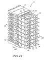
- Fig. 11 shows a fully assembled socket connector 20 including eight rows of connector modules 80 arranged in vertical column, with each row having four contacts 30 arranged in a horizontal row.
- Fig. 12 is a partial sectional view of the socket connector 20 showing the vertical and horizontal shielding portions 62, 64 of the shields 60 forming a virtual coaxial box around each signal contact 30. Coaxial shielding of each signal contact 30 allows transmission of high frequency signals at the points of connection with minimum interference and cross talk.
- the 8x4 contacts 30 are aligned with 8x4 pin insertion windows 94 in the front cap 90 when the connector modules 80 are assembled in the front cap 90.
- the pin insertion windows 94 guide the signal pins of a header connector (not shown) when the socket connector 20 is mated with a header connector.
- the signal pins of the header connector are received by the spring arms 38 of the contacts 30 of the socket connector 20.
- the number of rows and columns in the socket connector 20 can be chosen freely and independently of each other. For example, one may design a socket connector 20 having 16 rows, with 8 contacts per row, instead of 8 rows, with 4 contacts per row.
- the socket connector 20 of the present invention is particularly suited for high speed cable application.
- a connector module 80 may be pressed into a single row insulator (not shown) with a press-fit connection (also referred to as a single row concept).
- the assembled connector modules 80 may then be stacked to a desired height (e.g., 16 rows or 8 rows), and inserted in a perimetral housing (not shown).
- the housing holds the assembled connector modules 80 in place, and provides insulation and shielding around the stacked connector modules 80.
- the materials used for the socket connector 20 are as follows:
Landscapes
- Details Of Connecting Devices For Male And Female Coupling (AREA)
- Coupling Device And Connection With Printed Circuit (AREA)
- Connector Housings Or Holding Contact Members (AREA)
- Communication Cables (AREA)
- Cable Accessories (AREA)
- Acyclic And Carbocyclic Compounds In Medicinal Compositions (AREA)
- Pharmaceuticals Containing Other Organic And Inorganic Compounds (AREA)
Claims (8)
- Connecteur comprenant :caractérisé en ce que :une pluralité de contacts espacés horizontalement (30) arrangés en une rangée, chaque contact (30) comprenant une partie de contact s'étendant vers l'avant configurée de manière à engager un contact correspondant dans un connecteur de raccordement, une partie intermédiaire (34) et une partie de queue s'étendant vers l'arrière (36) ;un boítier isolant (50) sur les parties intermédiaires (34) des contacts (30), le boítier (50) comportant des ouvertures verticales espacées horizontalement (52) positionnées entre des parties intermédiaires, chaque ouverture s'étendant dans la direction du contact voisin (30), etun blindage (60) pour chaque contact, chaque blindage (60) présentant une partie de bride verticale à insérer dans une ouverture verticale (52) dans le boítier isolant (50), et une partie horizontale supérieure (64) s'étendant le long et au-dessus de la partie intermédiaire (34) du contact voisin (30),la partie horizontale supérieure (64) de chaque blindage (60) comprend une partie de blindage horizontale s'étendant vers l'avant (68) située au-dessus de la partie de contact s'étendant vers l'avant (32) de chaque contact (30), et dans lequel la partie de blindage horizontale s'étendant vers l'avant (68) de chaque blindage (60) comprend un boítier isolant (70) entourant la partie de blindage horizontale s'étendant vers l'avant (68).
- Connecteur selon la revendication 1, dans lequel les contacts (30) sont formés sur des bandes avec un espacement horizontal entre des contacts successifs (30) sur une première distance, les blindages (60) étant formés sur des bandes avec des blindages voisins espacés d'une deuxième distance égale à deux fois la première distance, de telle sorte qu'un premier ensemble de blindages (60) puisse être inséré dans chaque autre ouverture (52) tout en étant disposé sur une première bande, et qu'ensuite un deuxième ensemble de blindages (60) puisse être inséré dans les ouvertures vides (52) entre le premier ensemble de blindages (60) tout en étant disposé sur une deuxième bande.
- Connecteur selon la revendication 1 ou 2, dans lequel le boítier (50) est formé en surmoulant un isolant plastique sur les parties de contact intermédiaires (34) alors que les contacts (30) se trouvent sur une bande avec les ouvertures (52) formées respectivement entre des contacts voisins (30).
- Connecteur selon l'une quelconque des revendications 1 à 3, dans lequel la partie de contact s'étendant vers l'avant (32) de chaque contact (30) est configurée de manière à engager une broche de signal correspondante d'un connecteur de raccordement, dans lequel la partie de bride verticale (62) de chaque blindage (60) comprend une partie de blindage verticale s'étendant vers l'avant (60) située à la suite d'une partie de contact s'étendant vers l'avant (32) d'un contact voisin (30), et dans lequel la partie de blindage verticale s'étendant vers l'avant (66) est configurée de manière à engager une broche de terre d'un connecteur de raccordement, dans lequel la partie horizontale supérieure (64) de chaque blindage (60) comprend une partie de blindage horizontale s'étendant vers l'avant (68) située au-dessus de la partie de contact s'étendant vers l'avant (32) de chaque contact (30), et dans lequel la partie de blindage horizontale s'étendant vers l'avant (68) de chaque blindage (60) comprend un boítier isolant (70) entourant la partie de blindage horizontale s'étendant vers l'avant (68).
- Connecteur selon l'une quelconque des revendications 1 à 4, dans lequel le boítier isolant (70) entourant la partie de blindage horizontale s'étendant vers l'avant (68) est formée en surmoulant un isolant plastique sur la partie de blindage horizontale s'étendant vers l'avant (68) de la partie horizontale supérieure alors que les blindages (60) se trouvent sur une bande.
- Connecteur selon l'une quelconque des revendications 1 à 5, dans lequel les ouvertures verticales (52) sont formées comme des ouvertures.
- Connecteur selon l'une quelconque des revendications 1 à 6, dans lequel les parties de bride verticale et horizontale (62, 64) sont configurées de manière à former un blindage coaxial autour de chaque contact de signal (30).
- Arrangement de connecteur électrique comprenant:un boítier de connecteur (90); etune pluralité de connecteurs (80) selon l'une quelconque des revendications 1 à 7, les connecteurs (80) étant configurés de manière à être insérés dans le boítier de connecteur (90).
Applications Claiming Priority (3)
| Application Number | Priority Date | Filing Date | Title |
|---|---|---|---|
| US21491700P | 2000-06-29 | 2000-06-29 | |
| US214917P | 2000-06-29 | ||
| PCT/US2001/019848 WO2002003502A2 (fr) | 2000-06-29 | 2001-06-22 | Connecteur rapide |
Publications (2)
| Publication Number | Publication Date |
|---|---|
| EP1295363A2 EP1295363A2 (fr) | 2003-03-26 |
| EP1295363B1 true EP1295363B1 (fr) | 2005-04-13 |
Family
ID=22800904
Family Applications (1)
| Application Number | Title | Priority Date | Filing Date |
|---|---|---|---|
| EP01950373A Expired - Lifetime EP1295363B1 (fr) | 2000-06-29 | 2001-06-22 | Connecteur pour transmission d'un signal a haute vitesse |
Country Status (10)
| Country | Link |
|---|---|
| US (1) | US6478624B2 (fr) |
| EP (1) | EP1295363B1 (fr) |
| JP (1) | JP2004503056A (fr) |
| KR (1) | KR100808728B1 (fr) |
| CN (1) | CN1206775C (fr) |
| AT (1) | ATE293297T1 (fr) |
| AU (1) | AU2001271371A1 (fr) |
| DE (1) | DE60110070T2 (fr) |
| NO (1) | NO20026046L (fr) |
| WO (1) | WO2002003502A2 (fr) |
Families Citing this family (48)
| Publication number | Priority date | Publication date | Assignee | Title |
|---|---|---|---|---|
| NL1018175C2 (nl) * | 2001-05-30 | 2002-12-03 | Fci Mechelen N V | Stekkerblok en kabelconnector. |
| US6572410B1 (en) * | 2002-02-20 | 2003-06-03 | Fci Americas Technology, Inc. | Connection header and shield |
| DE10318638A1 (de) * | 2002-04-26 | 2003-11-13 | Honda Tsushin Kogyo | Elektrischer HF-Verbinder ohne Erdungsanschlüsse |
| US6638079B1 (en) * | 2002-05-21 | 2003-10-28 | Hon Hai Precision Ind. Co., Ltd. | Customizable electrical connector |
| JP3746250B2 (ja) * | 2002-06-28 | 2006-02-15 | 日本航空電子工業株式会社 | ケーブルコネクタ |
| US6890221B2 (en) * | 2003-01-27 | 2005-05-10 | Fci Americas Technology, Inc. | Power connector with male and female contacts |
| EP1594423B1 (fr) * | 2003-02-14 | 2009-01-07 | DePuy Spine, Inc. | Dispositif et procede de fusion intervertebrale forme in-situ |
| JP3841348B2 (ja) * | 2003-02-25 | 2006-11-01 | 日本航空電子工業株式会社 | コネクタのグラウンド構造 |
| JP2004273154A (ja) * | 2003-03-05 | 2004-09-30 | Yazaki Corp | ジョイントコネクタ及び端子 |
| US6827611B1 (en) * | 2003-06-18 | 2004-12-07 | Teradyne, Inc. | Electrical connector with multi-beam contact |
| US6884117B2 (en) * | 2003-08-29 | 2005-04-26 | Hon Hai Precision Ind. Co., Ltd. | Electrical connector having circuit board modules positioned between metal stiffener and a housing |
| JP3909769B2 (ja) * | 2004-01-09 | 2007-04-25 | 日本航空電子工業株式会社 | コネクタ |
| US7513797B2 (en) | 2004-02-27 | 2009-04-07 | 3M Innovative Properties Company | Connector apparatus |
| DE102004060782B3 (de) * | 2004-12-17 | 2006-03-09 | Harting Electronics Gmbh & Co. Kg | Geschirmter, hochpoliger Leiterplattensteckverbinder |
| US7163421B1 (en) * | 2005-06-30 | 2007-01-16 | Amphenol Corporation | High speed high density electrical connector |
| US7410392B2 (en) * | 2005-12-15 | 2008-08-12 | Tyco Electronics Corporation | Electrical connector assembly having selective arrangement of signal and ground contacts |
| US7959466B2 (en) * | 2007-08-01 | 2011-06-14 | Lotes Co., Ltd. | Individually filtered terminals and shielded circuit board through-holes |
| US7575482B1 (en) * | 2008-04-22 | 2009-08-18 | Tyco Electronics Corporation | Electrical connector with enhanced back end design |
| US8221162B2 (en) * | 2008-07-24 | 2012-07-17 | 3M Innovative Properties Company | Electrical connector |
| US7621760B1 (en) | 2008-07-24 | 2009-11-24 | 3M Innovative Properties Company | Electrical connector |
| WO2011090634A2 (fr) * | 2009-12-30 | 2011-07-28 | Fci | Connecteur électrique comportant un boîtier électriquement isolant et des contacts de masse communs |
| WO2011100740A2 (fr) | 2010-02-15 | 2011-08-18 | Molex Incorporated | Connecteur à couplage différentiel |
| US7976340B1 (en) * | 2010-03-12 | 2011-07-12 | Tyco Electronics Corporation | Connector system with electromagnetic interference shielding |
| CN107069274B (zh) | 2010-05-07 | 2020-08-18 | 安费诺有限公司 | 高性能线缆连接器 |
| JP5756608B2 (ja) * | 2010-07-15 | 2015-07-29 | 矢崎総業株式会社 | コネクタ |
| JP5209038B2 (ja) * | 2010-12-08 | 2013-06-12 | 日立オートモティブシステムズ株式会社 | コネクタ及びその製造方法 |
| EP2652843A1 (fr) * | 2010-12-13 | 2013-10-23 | Fci | Bloc connecteur blindé |
| CN104704682B (zh) | 2012-08-22 | 2017-03-22 | 安费诺有限公司 | 高频电连接器 |
| DE202012008969U1 (de) | 2012-09-18 | 2012-11-09 | Rosenberger Hochfrequenztechnik Gmbh & Co. Kg | Steckverbindung |
| US9281624B2 (en) * | 2013-08-16 | 2016-03-08 | Tyco Electronics Corporation | Electrical connector with signal pathways and a system having the same |
| CN110247219B (zh) | 2014-01-22 | 2021-06-15 | 安费诺有限公司 | 电连接器 |
| US9407045B2 (en) * | 2014-12-16 | 2016-08-02 | Tyco Electronics Corporation | Electrical connector with joined ground shields |
| CN105990763B (zh) * | 2015-02-15 | 2019-10-29 | 泰科电子(上海)有限公司 | 电连接器 |
| US9444189B1 (en) * | 2015-05-26 | 2016-09-13 | Tyco Electronics Corporation | Pluggable connector configured for crosstalk reduction and resonance control |
| CN108701922B (zh) | 2015-07-07 | 2020-02-14 | Afci亚洲私人有限公司 | 电连接器 |
| WO2018039164A1 (fr) | 2016-08-23 | 2018-03-01 | Amphenol Corporation | Connecteur configurable pour hautes performances |
| JP7019681B2 (ja) | 2016-09-29 | 2022-02-15 | スリーエム イノベイティブ プロパティズ カンパニー | 回路基板への無はんだ実装のためのコネクタアセンブリ |
| TWI656700B (zh) * | 2017-08-23 | 2019-04-11 | 格稜股份有限公司 | 垂直式高速連接器及其導電模組 |
| CN108963667B (zh) * | 2018-07-09 | 2020-07-24 | 肯上科技股份有限公司 | 高频连接器接地结构 |
| CN208862209U (zh) | 2018-09-26 | 2019-05-14 | 安费诺东亚电子科技(深圳)有限公司 | 一种连接器及其应用的pcb板 |
| CN109326909A (zh) * | 2018-11-20 | 2019-02-12 | 安费诺商用电子产品(成都)有限公司 | 一种高密度大功率卡类连接端子以及连接器 |
| TWI889666B (zh) | 2019-02-19 | 2025-07-11 | 美商安芬諾股份有限公司 | 電連接器及用於製造電連接器之方法 |
| TWI887339B (zh) | 2020-01-27 | 2025-06-21 | 美商Fci美國有限責任公司 | 高速及高密度之直接耦合垂直式連接器 |
| WO2021154702A1 (fr) | 2020-01-27 | 2021-08-05 | Fci Usa Llc | Connecteur à vitesse élevée |
| CN215816516U (zh) | 2020-09-22 | 2022-02-11 | 安费诺商用电子产品(成都)有限公司 | 电连接器 |
| CN213636403U (zh) | 2020-09-25 | 2021-07-06 | 安费诺商用电子产品(成都)有限公司 | 电连接器 |
| CN215266741U (zh) | 2021-08-13 | 2021-12-21 | 安费诺商用电子产品(成都)有限公司 | 一种满足高带宽传输的高性能卡类连接器 |
| JP2023141246A (ja) * | 2022-03-23 | 2023-10-05 | イリソ電子工業株式会社 | コネクタセット及び第一コネクタ |
Family Cites Families (72)
| Publication number | Priority date | Publication date | Assignee | Title |
|---|---|---|---|---|
| US4538866A (en) | 1983-03-07 | 1985-09-03 | Teradyne, Inc. | Backplane connector |
| US4571014A (en) | 1984-05-02 | 1986-02-18 | At&T Bell Laboratories | High frequency modular connector |
| US4869677A (en) | 1984-08-17 | 1989-09-26 | Teradyne, Inc. | Backplane connector |
| US4655518A (en) | 1984-08-17 | 1987-04-07 | Teradyne, Inc. | Backplane connector |
| US4724180A (en) | 1985-08-05 | 1988-02-09 | Teradyne, Inc. | Electrically shielded connectors |
| US4659155A (en) | 1985-11-19 | 1987-04-21 | Teradyne, Inc. | Backplane-daughter board connector |
| DE3605316A1 (de) | 1986-02-19 | 1987-08-20 | Siemens Ag | Hochpoliger steckverbinder |
| US4836791A (en) | 1987-11-16 | 1989-06-06 | Amp Incorporated | High density coax connector |
| US4854899A (en) | 1987-11-24 | 1989-08-08 | Elcon Products International Company | Terminal bus junction with multiple, displaced contact points |
| US4871321A (en) | 1988-03-22 | 1989-10-03 | Teradyne, Inc. | Electrical connector |
| US4846727A (en) | 1988-04-11 | 1989-07-11 | Amp Incorporated | Reference conductor for improving signal integrity in electrical connectors |
| US4867690A (en) | 1988-06-17 | 1989-09-19 | Amp Incorporated | Electrical connector system |
| US4909743A (en) | 1988-10-14 | 1990-03-20 | Teradyne, Inc. | Electrical connector |
| US4975084A (en) | 1988-10-17 | 1990-12-04 | Amp Incorporated | Electrical connector system |
| US4914062A (en) * | 1989-02-15 | 1990-04-03 | W. L. Gore & Associates, Inc. | Shielded right angled header |
| US4932888A (en) | 1989-06-16 | 1990-06-12 | Augat Inc. | Multi-row box connector |
| DE69018000T2 (de) | 1989-10-10 | 1995-09-28 | Whitaker Corp | Rückwandsteckverbinder mit angepasster Impedanz. |
| GB8928777D0 (en) | 1989-12-20 | 1990-02-28 | Amp Holland | Sheilded backplane connector |
| AU7736691A (en) | 1990-06-08 | 1991-12-12 | E.I. Du Pont De Nemours And Company | Connectors with ground structure |
| US5133679A (en) | 1990-06-08 | 1992-07-28 | E. I. Du Pont De Nemours And Company | Connectors with ground structure |
| US5175928A (en) | 1990-06-11 | 1993-01-05 | Amp Incorporated | Method of manufacturing an electrical connection assembly |
| US5046960A (en) | 1990-12-20 | 1991-09-10 | Amp Incorporated | High density connector system |
| US5141445A (en) | 1991-04-30 | 1992-08-25 | Thomas & Betts Corporation | Surface mounted electrical connector |
| US5137475A (en) | 1991-05-31 | 1992-08-11 | Tronomed, Inc. | Medical electrical connector for flexible electrodes |
| JPH0521110A (ja) | 1991-07-10 | 1993-01-29 | Amp Japan Ltd | シールド型電気コネクタ |
| JP2559833Y2 (ja) | 1991-10-17 | 1998-01-19 | 日本エー・エム・ピー株式会社 | モジューラ電気コネクタ用ホルダ |
| GB9205087D0 (en) | 1992-03-09 | 1992-04-22 | Amp Holland | Sheilded back plane connector |
| GB9205088D0 (en) | 1992-03-09 | 1992-04-22 | Amp Holland | Shielded back plane connector |
| US5282752A (en) | 1992-08-07 | 1994-02-01 | E. I. Du Pont De Nemours And Company | Combination connector tool |
| US5487682A (en) * | 1992-09-08 | 1996-01-30 | The Whitaker Corporation | Shielded data connector |
| IL106494A (en) | 1992-09-08 | 1996-10-31 | Whitaker Corp | Shielded data connector |
| DE4241486A1 (de) | 1992-12-09 | 1994-06-16 | Antelec Eng Gmbh | Umformer |
| US5620340A (en) * | 1992-12-31 | 1997-04-15 | Berg Technology, Inc. | Connector with improved shielding |
| NL9202301A (nl) | 1992-12-31 | 1994-07-18 | Du Pont Nederland | Connector met verbeterde afscherming. |
| US5376021A (en) * | 1993-02-05 | 1994-12-27 | Thomas & Betts Corporation | Enhanced performance data connector |
| US5360349A (en) | 1993-03-31 | 1994-11-01 | Teradyne, Inc. | Power connector |
| US5403206A (en) | 1993-04-05 | 1995-04-04 | Teradyne, Inc. | Shielded electrical connector |
| DE9311782U1 (de) | 1993-08-06 | 1993-09-23 | Siemens AG, 80333 München | Leiterplatten-steckverbinder mit zwei an zueinander senkrechten leiterplatten angeordneten geschirmten kontaktleisten |
| JPH07122335A (ja) * | 1993-10-20 | 1995-05-12 | Minnesota Mining & Mfg Co <3M> | 高速伝送用コネクタ |
| EP0670615B1 (fr) | 1994-03-03 | 1997-02-05 | Siemens Aktiengesellschaft | Connecteur pour câblages de panneau arrière |
| US5618208A (en) | 1994-06-03 | 1997-04-08 | Siemens Medical Systems, Inc. | Fully insulated, fully shielded electrical connector arrangement |
| EP0718928B1 (fr) | 1994-12-22 | 1999-06-16 | Siemens Aktiengesellschaft | Assemblage de connecteur électrique |
| DE4446098C2 (de) | 1994-12-22 | 1998-11-26 | Siemens Ag | Elektrischer Verbinder mit Abschirmung |
| US5788537A (en) | 1995-03-27 | 1998-08-04 | The Whiteker Corporation | Shield assembly for an electrical connector |
| US5704793A (en) | 1995-04-17 | 1998-01-06 | Teradyne, Inc. | High speed high density connector for electronic signals |
| US5700164A (en) | 1995-06-16 | 1997-12-23 | The Whitaker Corporation | Electrical connector with shield |
| US5672064A (en) | 1995-12-21 | 1997-09-30 | Teradyne, Inc. | Stiffener for electrical connector |
| US5702258A (en) * | 1996-03-28 | 1997-12-30 | Teradyne, Inc. | Electrical connector assembled from wafers |
| US5664968A (en) | 1996-03-29 | 1997-09-09 | The Whitaker Corporation | Connector assembly with shielded modules |
| FR2746971B1 (fr) | 1996-04-01 | 1998-04-30 | Framatome Connectors France | Connecteur blinde miniature a tiges de contact coudees |
| JP3251849B2 (ja) | 1996-05-17 | 2002-01-28 | タイコエレクトロニクスアンプ株式会社 | シールド型コネクタ |
| US5738544A (en) | 1996-06-27 | 1998-04-14 | The Whitaker Corporation | Shielded electrical connector |
| US5755595A (en) | 1996-06-27 | 1998-05-26 | Whitaker Corporation | Shielded electrical connector |
| ATE188578T1 (de) | 1996-07-02 | 2000-01-15 | Siemens Ag | Steckverbinder mit abschirmung |
| GB9615495D0 (en) | 1996-07-24 | 1996-09-04 | Amp Holland | Shielded electrical connector assembly |
| US5788538A (en) | 1996-07-31 | 1998-08-04 | Berg Technology, Inc. | Shield for modular jack |
| JP2000516385A (ja) * | 1996-08-20 | 2000-12-05 | バーグ・テクノロジー・インコーポレーテッド | 高速モジュラー電気コネクタ及びこれに使用されるレセプタクル |
| US5797770A (en) | 1996-08-21 | 1998-08-25 | The Whitaker Corporation | Shielded electrical connector |
| JP3070003B2 (ja) | 1996-09-06 | 2000-07-24 | タイコエレクトロニクスアンプ株式会社 | シールド型コネクタ及びその製造方法 |
| US5795191A (en) | 1996-09-11 | 1998-08-18 | Preputnick; George | Connector assembly with shielded modules and method of making same |
| JPH10134877A (ja) | 1996-10-25 | 1998-05-22 | Amp Japan Ltd | コネクタ用端子保護カバー |
| US6089882A (en) | 1996-11-27 | 2000-07-18 | The Whitaker Corporation | Memory card connector with grounding clip |
| US6183301B1 (en) | 1997-01-16 | 2001-02-06 | Berg Technology, Inc. | Surface mount connector with integrated PCB assembly |
| US5993259A (en) | 1997-02-07 | 1999-11-30 | Teradyne, Inc. | High speed, high density electrical connector |
| US5980321A (en) | 1997-02-07 | 1999-11-09 | Teradyne, Inc. | High speed, high density electrical connector |
| US5820412A (en) | 1997-03-18 | 1998-10-13 | The Whitaker Corporation | Connector shield with cable crimp support |
| US5967846A (en) | 1997-04-22 | 1999-10-19 | The Whitaker Corporation | Shields for electrical connector mated pair |
| US5863222A (en) | 1997-06-03 | 1999-01-26 | The Whitaker Corporation | Shielded electrical connector |
| US6227882B1 (en) | 1997-10-01 | 2001-05-08 | Berg Technology, Inc. | Connector for electrical isolation in a condensed area |
| WO1999026321A1 (fr) | 1997-11-19 | 1999-05-27 | The Whitaker Corporation | Connecteur electrique blinde |
| US6293827B1 (en) * | 2000-02-03 | 2001-09-25 | Teradyne, Inc. | Differential signal electrical connector |
| US6290515B1 (en) * | 2000-09-05 | 2001-09-18 | Hon Hai Precision Ind. Co., Ltd. | Electrical connector assembly having grounding buses |
-
2001
- 2001-06-22 AT AT01950373T patent/ATE293297T1/de not_active IP Right Cessation
- 2001-06-22 CN CNB018119379A patent/CN1206775C/zh not_active Expired - Fee Related
- 2001-06-22 JP JP2002507476A patent/JP2004503056A/ja active Pending
- 2001-06-22 WO PCT/US2001/019848 patent/WO2002003502A2/fr not_active Ceased
- 2001-06-22 US US09/887,890 patent/US6478624B2/en not_active Expired - Fee Related
- 2001-06-22 EP EP01950373A patent/EP1295363B1/fr not_active Expired - Lifetime
- 2001-06-22 DE DE60110070T patent/DE60110070T2/de not_active Expired - Lifetime
- 2001-06-22 KR KR1020027017906A patent/KR100808728B1/ko not_active Expired - Fee Related
- 2001-06-22 AU AU2001271371A patent/AU2001271371A1/en not_active Abandoned
-
2002
- 2002-12-16 NO NO20026046A patent/NO20026046L/no not_active Application Discontinuation
Also Published As
| Publication number | Publication date |
|---|---|
| DE60110070T2 (de) | 2006-05-11 |
| WO2002003502A2 (fr) | 2002-01-10 |
| NO20026046D0 (no) | 2002-12-16 |
| KR20030028766A (ko) | 2003-04-10 |
| DE60110070D1 (de) | 2005-05-19 |
| EP1295363A2 (fr) | 2003-03-26 |
| KR100808728B1 (ko) | 2008-02-29 |
| US20020022401A1 (en) | 2002-02-21 |
| ATE293297T1 (de) | 2005-04-15 |
| CN1439186A (zh) | 2003-08-27 |
| WO2002003502A3 (fr) | 2002-05-10 |
| US6478624B2 (en) | 2002-11-12 |
| NO20026046L (no) | 2003-02-11 |
| JP2004503056A (ja) | 2004-01-29 |
| AU2001271371A1 (en) | 2002-01-14 |
| CN1206775C (zh) | 2005-06-15 |
Similar Documents
| Publication | Publication Date | Title |
|---|---|---|
| EP1295363B1 (fr) | Connecteur pour transmission d'un signal a haute vitesse | |
| EP0072063B1 (fr) | Connecteur de câble coaxial à deux ou trois rangées | |
| US7147512B2 (en) | Connector assembly | |
| KR102439060B1 (ko) | 커넥터 조립체 | |
| US6338652B1 (en) | Low profile cable connector with grounding means | |
| US7572148B1 (en) | Coupler for interconnecting electrical connectors | |
| US6273753B1 (en) | Twinax coaxial flat cable connector assembly | |
| US8449330B1 (en) | Cable header connector | |
| US6116943A (en) | Modular plug having a circuit board | |
| US4838811A (en) | Modular connector with EMI countermeasure | |
| CN113555708A (zh) | 插头连接器 | |
| US7094103B2 (en) | Cable connector assembly having improved shield members | |
| US6250959B1 (en) | Connector for coaxial cables with very fine conductors | |
| US7311552B1 (en) | Micro coaxial cable connector assembly | |
| WO2013085732A1 (fr) | Connecteur d'en-tête de câble | |
| EP1741164A1 (fr) | Connecteur blinde a faible inductance | |
| US11239617B2 (en) | Cable receptacle connector | |
| US5421735A (en) | Modular coaxial cable connector | |
| US6544050B1 (en) | Electrical cable connector assembly | |
| US11909147B2 (en) | Cable connector assembly | |
| JP3425634B2 (ja) | 高速ケーブル用のシールド終端機構を備えた電気コネクタ | |
| US4674822A (en) | Multi-conductor shielded cable | |
| US20240347982A1 (en) | Cable card assembly of an electrical connector having capacitors | |
| KR100803228B1 (ko) | 동축 케이블용 커넥터 | |
| EP1263092B1 (fr) | Connecteur pour câble de réseau |
Legal Events
| Date | Code | Title | Description |
|---|---|---|---|
| PUAI | Public reference made under article 153(3) epc to a published international application that has entered the european phase |
Free format text: ORIGINAL CODE: 0009012 |
|
| 17P | Request for examination filed |
Effective date: 20021214 |
|
| AK | Designated contracting states |
Kind code of ref document: A2 Designated state(s): AT BE CH CY DE DK ES FI FR GB GR IE IT LI LU MC NL PT SE TR Designated state(s): AT BE CH CY DE DK ES FI FR GB GR IE IT LI LU MC NL PT SE TR |
|
| AX | Request for extension of the european patent |
Extension state: AL LT LV MK RO SI |
|
| RIN1 | Information on inventor provided before grant (corrected) |
Inventor name: RAMEY, SAMUEL, C. Inventor name: KUSTERS, JOHANNES, PETRUS, MARIA |
|
| RIN1 | Information on inventor provided before grant (corrected) |
Inventor name: RAMEY, SAMUEL C. Inventor name: KUSTERS, JOHANNES PETRUS MARIA |
|
| RIN1 | Information on inventor provided before grant (corrected) |
Inventor name: RAMEY, SAMUEL C. Inventor name: KUSTERS, JOHANNES PETRUS MARIA |
|
| RIN1 | Information on inventor provided before grant (corrected) |
Inventor name: RAMEY, SAMUEL C. Inventor name: KUSTERS, JOHANNES PETRUS MARIA |
|
| 17Q | First examination report despatched |
Effective date: 20031112 |
|
| GRAP | Despatch of communication of intention to grant a patent |
Free format text: ORIGINAL CODE: EPIDOSNIGR1 |
|
| GRAS | Grant fee paid |
Free format text: ORIGINAL CODE: EPIDOSNIGR3 |
|
| GRAA | (expected) grant |
Free format text: ORIGINAL CODE: 0009210 |
|
| RIN1 | Information on inventor provided before grant (corrected) |
Inventor name: RAMEY, SAMUEL C. Inventor name: KUSTERS, JOHANNES PETRUS MARIA |
|
| AK | Designated contracting states |
Kind code of ref document: B1 Designated state(s): AT BE CH CY DE DK ES FI FR GB GR IE IT LI LU MC NL PT SE TR |
|
| PG25 | Lapsed in a contracting state [announced via postgrant information from national office to epo] |
Ref country code: TR Free format text: LAPSE BECAUSE OF FAILURE TO SUBMIT A TRANSLATION OF THE DESCRIPTION OR TO PAY THE FEE WITHIN THE PRESCRIBED TIME-LIMIT Effective date: 20050413 Ref country code: NL Free format text: LAPSE BECAUSE OF FAILURE TO SUBMIT A TRANSLATION OF THE DESCRIPTION OR TO PAY THE FEE WITHIN THE PRESCRIBED TIME-LIMIT Effective date: 20050413 Ref country code: LI Free format text: LAPSE BECAUSE OF FAILURE TO SUBMIT A TRANSLATION OF THE DESCRIPTION OR TO PAY THE FEE WITHIN THE PRESCRIBED TIME-LIMIT Effective date: 20050413 Ref country code: IT Free format text: LAPSE BECAUSE OF FAILURE TO SUBMIT A TRANSLATION OF THE DESCRIPTION OR TO PAY THE FEE WITHIN THE PRESCRIBED TIME-LIMIT;WARNING: LAPSES OF ITALIAN PATENTS WITH EFFECTIVE DATE BEFORE 2007 MAY HAVE OCCURRED AT ANY TIME BEFORE 2007. THE CORRECT EFFECTIVE DATE MAY BE DIFFERENT FROM THE ONE RECORDED. Effective date: 20050413 Ref country code: FI Free format text: LAPSE BECAUSE OF FAILURE TO SUBMIT A TRANSLATION OF THE DESCRIPTION OR TO PAY THE FEE WITHIN THE PRESCRIBED TIME-LIMIT Effective date: 20050413 Ref country code: CH Free format text: LAPSE BECAUSE OF FAILURE TO SUBMIT A TRANSLATION OF THE DESCRIPTION OR TO PAY THE FEE WITHIN THE PRESCRIBED TIME-LIMIT Effective date: 20050413 Ref country code: BE Free format text: LAPSE BECAUSE OF FAILURE TO SUBMIT A TRANSLATION OF THE DESCRIPTION OR TO PAY THE FEE WITHIN THE PRESCRIBED TIME-LIMIT Effective date: 20050413 Ref country code: AT Free format text: LAPSE BECAUSE OF FAILURE TO SUBMIT A TRANSLATION OF THE DESCRIPTION OR TO PAY THE FEE WITHIN THE PRESCRIBED TIME-LIMIT Effective date: 20050413 |
|
| REG | Reference to a national code |
Ref country code: GB Ref legal event code: FG4D |
|
| REG | Reference to a national code |
Ref country code: CH Ref legal event code: EP |
|
| REG | Reference to a national code |
Ref country code: IE Ref legal event code: FG4D |
|
| REF | Corresponds to: |
Ref document number: 60110070 Country of ref document: DE Date of ref document: 20050519 Kind code of ref document: P |
|
| PG25 | Lapsed in a contracting state [announced via postgrant information from national office to epo] |
Ref country code: LU Free format text: LAPSE BECAUSE OF NON-PAYMENT OF DUE FEES Effective date: 20050622 Ref country code: IE Free format text: LAPSE BECAUSE OF NON-PAYMENT OF DUE FEES Effective date: 20050622 Ref country code: CY Free format text: LAPSE BECAUSE OF FAILURE TO SUBMIT A TRANSLATION OF THE DESCRIPTION OR TO PAY THE FEE WITHIN THE PRESCRIBED TIME-LIMIT Effective date: 20050622 |
|
| PG25 | Lapsed in a contracting state [announced via postgrant information from national office to epo] |
Ref country code: MC Free format text: LAPSE BECAUSE OF NON-PAYMENT OF DUE FEES Effective date: 20050630 |
|
| PG25 | Lapsed in a contracting state [announced via postgrant information from national office to epo] |
Ref country code: SE Free format text: LAPSE BECAUSE OF FAILURE TO SUBMIT A TRANSLATION OF THE DESCRIPTION OR TO PAY THE FEE WITHIN THE PRESCRIBED TIME-LIMIT Effective date: 20050713 Ref country code: GR Free format text: LAPSE BECAUSE OF FAILURE TO SUBMIT A TRANSLATION OF THE DESCRIPTION OR TO PAY THE FEE WITHIN THE PRESCRIBED TIME-LIMIT Effective date: 20050713 Ref country code: GB Free format text: LAPSE BECAUSE OF NON-PAYMENT OF DUE FEES Effective date: 20050713 Ref country code: DK Free format text: LAPSE BECAUSE OF FAILURE TO SUBMIT A TRANSLATION OF THE DESCRIPTION OR TO PAY THE FEE WITHIN THE PRESCRIBED TIME-LIMIT Effective date: 20050713 |
|
| PG25 | Lapsed in a contracting state [announced via postgrant information from national office to epo] |
Ref country code: ES Free format text: LAPSE BECAUSE OF FAILURE TO SUBMIT A TRANSLATION OF THE DESCRIPTION OR TO PAY THE FEE WITHIN THE PRESCRIBED TIME-LIMIT Effective date: 20050724 |
|
| PG25 | Lapsed in a contracting state [announced via postgrant information from national office to epo] |
Ref country code: PT Free format text: LAPSE BECAUSE OF FAILURE TO SUBMIT A TRANSLATION OF THE DESCRIPTION OR TO PAY THE FEE WITHIN THE PRESCRIBED TIME-LIMIT Effective date: 20050913 |
|
| NLV1 | Nl: lapsed or annulled due to failure to fulfill the requirements of art. 29p and 29m of the patents act | ||
| REG | Reference to a national code |
Ref country code: CH Ref legal event code: PL |
|
| PLBE | No opposition filed within time limit |
Free format text: ORIGINAL CODE: 0009261 |
|
| STAA | Information on the status of an ep patent application or granted ep patent |
Free format text: STATUS: NO OPPOSITION FILED WITHIN TIME LIMIT |
|
| ET | Fr: translation filed | ||
| REG | Reference to a national code |
Ref country code: IE Ref legal event code: MM4A |
|
| GBPC | Gb: european patent ceased through non-payment of renewal fee |
Effective date: 20050713 |
|
| 26N | No opposition filed |
Effective date: 20060116 |
|
| PGFP | Annual fee paid to national office [announced via postgrant information from national office to epo] |
Ref country code: FR Payment date: 20070618 Year of fee payment: 7 |
|
| REG | Reference to a national code |
Ref country code: FR Ref legal event code: ST Effective date: 20090228 |
|
| PG25 | Lapsed in a contracting state [announced via postgrant information from national office to epo] |
Ref country code: FR Free format text: LAPSE BECAUSE OF NON-PAYMENT OF DUE FEES Effective date: 20080630 |
|
| PGFP | Annual fee paid to national office [announced via postgrant information from national office to epo] |
Ref country code: DE Payment date: 20100616 Year of fee payment: 10 |
|
| REG | Reference to a national code |
Ref country code: DE Ref legal event code: R119 Ref document number: 60110070 Country of ref document: DE Effective date: 20120103 |
|
| PG25 | Lapsed in a contracting state [announced via postgrant information from national office to epo] |
Ref country code: DE Free format text: LAPSE BECAUSE OF NON-PAYMENT OF DUE FEES Effective date: 20120103 |