EP1295372B1 - Abdeckung zum verschliessen einer öffnung in einer schalttafel - Google Patents
Abdeckung zum verschliessen einer öffnung in einer schalttafel Download PDFInfo
- Publication number
- EP1295372B1 EP1295372B1 EP01936808A EP01936808A EP1295372B1 EP 1295372 B1 EP1295372 B1 EP 1295372B1 EP 01936808 A EP01936808 A EP 01936808A EP 01936808 A EP01936808 A EP 01936808A EP 1295372 B1 EP1295372 B1 EP 1295372B1
- Authority
- EP
- European Patent Office
- Prior art keywords
- plate
- crosspiece
- panel
- opening
- projection
- Prior art date
- Legal status (The legal status is an assumption and is not a legal conclusion. Google has not performed a legal analysis and makes no representation as to the accuracy of the status listed.)
- Expired - Lifetime
Links
- 230000000452 restraining effect Effects 0.000 claims abstract description 13
- 230000000295 complement effect Effects 0.000 claims description 7
- 238000005452 bending Methods 0.000 claims description 5
- 230000008878 coupling Effects 0.000 claims description 4
- 238000010168 coupling process Methods 0.000 claims description 4
- 238000005859 coupling reaction Methods 0.000 claims description 4
- 238000004519 manufacturing process Methods 0.000 description 4
- 239000002184 metal Substances 0.000 description 3
- 229920003023 plastic Polymers 0.000 description 3
- 239000004033 plastic Substances 0.000 description 3
- 230000002411 adverse Effects 0.000 description 1
- 238000006243 chemical reaction Methods 0.000 description 1
- 230000037431 insertion Effects 0.000 description 1
- 238000003780 insertion Methods 0.000 description 1
- 238000009434 installation Methods 0.000 description 1
Images


Classifications
-
- H—ELECTRICITY
- H02—GENERATION; CONVERSION OR DISTRIBUTION OF ELECTRIC POWER
- H02B—BOARDS, SUBSTATIONS OR SWITCHING ARRANGEMENTS FOR THE SUPPLY OR DISTRIBUTION OF ELECTRIC POWER
- H02B1/00—Frameworks, boards, panels, desks, casings; Details of substations or switching arrangements
- H02B1/015—Boards, panels, desks; Parts thereof or accessories therefor
- H02B1/06—Boards, panels, desks; Parts thereof or accessories therefor having associated enclosures, e.g. for preventing access to live parts
-
- H—ELECTRICITY
- H02—GENERATION; CONVERSION OR DISTRIBUTION OF ELECTRIC POWER
- H02B—BOARDS, SUBSTATIONS OR SWITCHING ARRANGEMENTS FOR THE SUPPLY OR DISTRIBUTION OF ELECTRIC POWER
- H02B1/00—Frameworks, boards, panels, desks, casings; Details of substations or switching arrangements
- H02B1/015—Boards, panels, desks; Parts thereof or accessories therefor
- H02B2001/0155—Removable shutters for non-used openings
Definitions
- the present invention relates to electrical distribution boards and, more particularly, to a cover for closing an opening in a panel of an electrical distribution board as defined in the preamble of claim 1 and known from DE-A-35 38 177 .
- An electrical distribution board is generally constituted by a metal framework composed of upright members and cross-members, by bars for supporting devices, and by sheet-metal panels fixed to the framework, and is designed for containing internal distribution and connecting structures and electrical devices, at least some of which are accessible from the exterior.
- the panels are provided with windows of standard dimensions, for example, such as to house the maximum number of switches provided for by the particular type of distribution board.
- windows of standard dimensions for example, such as to house the maximum number of switches provided for by the particular type of distribution board.
- Covers of various types are known and are usually constituted by plastics plates with fixing elements which can be snap-engaged between two opposed edges of the opening to be closed. It has been found that this closure system is not always reliable because the grip of the fixing elements is often insufficient so that it is easy to remove the covers manually without tools. This leads to serious risks to personal safety because the spaces which remain open permit potentially dangerous situations such as the deliberate or unintentional insertion of fingers or metal objects. To render this closure system more effective and safer, it would be necessary for the windows and the covers to be manufactured with quite tight dimensional tolerances, but this would adversely affect manufacturing costs.
- the main aim of the present invention is to provide a closure system which is safer than the known system and which does not require tight manufacturing tolerances.
- the plate 14 closes an opening having the width of six modules and, as can be seen in Figures 3 and 4 in particular, is placed with its opposed edges 15 over two opposed edge areas of the window 11.
- Two appendages 16 extend parallel to the edges of the plate to form means for snap-fixing the plate to the panel. More particularly, the appendages 16 are formed integrally with the plate 10 and each has an inclined plane 17 as a lead-in surface for coupling with the opening to be closed, and an engagement tooth 18.
- the appendages are relatively thin, at least at the point of connection to the plate, to permit resilient bending, and their distance apart is selected so as to permit snap-restraint of the plate in the opening.
- the means for fixing the plate to the panel also comprise two crosspieces 20 which are fitted, by means of further restraining elements, on the inner face of the panel, that is, the opposite face to that from which the operating members of the switches 12 project. More particularly, these further restraining elements are constituted by two resilient tabs 21 which project from the crosspiece 20, are integral therewith, and have respective saw-tooth-shaped faces 22, and by the appendages 16 of the plate, which are shaped in a complementary manner with corresponding saw-teeth 19.
- the tabs 21 of each crosspiece are spaced apart by a distance such as to permit snap-restraint between their teeth 22 and the teeth 19 of the appendages.
- the crosspieces 20 prevent the appendage 16 from bending in the direction such as to be released from the panel.
- the plate cannot therefore be removed by operating from outside the panel but can be removed only by first removing the crosspieces 20 from the inside of the panel.
- the crosspieces 20 are bent at right angles at their ends so as to form two spacing and bearing elements 23. These elements are of a size such as to exert a predetermined pressure on the panel when the respective crosspiece is in position, owing to a resilient reaction of the end portions of the crosspiece to bending.
- the crosspiece is advantageously stiffened by a rib 24 formed on the portion which joins the two tabs 21 but not on the end portions, precisely to permit the above-mentioned bending.
- the pressure of the bearing elements 23 on the inner face of the panel prevents any movement of the plate 14 owing to any play due to the tolerances of the thickness of the panel 10 and of the width of the window 11.
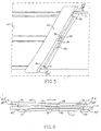
- the closure plate, indicated 14' when the closure plate, indicated 14', is fitted on a panel 10 in order at least partially to close a window 11 thereof, it appears like the plate 14 in Figure 1 . It is also preferably formed from a rigid plastics strip with predetermined breakage nicks and is placed with its opposed edges 15' over opposed edge areas of the window 11.
- the cover has two crosspieces on the inner face of the plate, of which only one crosspiece, indicated 20', is shown in the drawings, as well as restraining means, but differs from that of Figures 1 to 4 in various constructional aspects.
- the plate 14' has a projection in the form of a rib 30 of square cross-section along one of the edge areas placed over the edge of the window 11 and a recess, in the form of a square-sectioned groove 31 along the other edge area.
- the plate 14' has a cavity 32 which extends along the entire plate in this embodiment and is partially undercut so as to form a channel partially covered by a projecting edge portion 33.
- the crosspiece 20' is shaped substantially like the plate 14' but is mounted in a reversed arrangement, that is, it has a square-sectioned rib 34 complementary with the groove 31 of the plate, a groove 35 complementary with the rib 30 of the plate, and a cavity 36 partially undercut to form a channel with a projecting edge portion 37.
- the plate 14' is placed on the panel 10 in a manner such that the rib 30 is in contact, or almost in contact, with an inner edge of the opening and, at the same time, the crosspiece 20' is arranged in a manner such that the projecting edge portion 37 is above the channel 32 of the plate.
- the edge of the crosspiece 20' in the vicinity of the groove 35 is disposed slightly beyond the edge of the opening, and the rib 34 of the crosspiece 20' is in contact with the inner face of the panel 10 a certain distance from the.other edge of the opening.
- the edge portion 37 of the crosspiece enters the channel 32 of the plate. If, at the same time, the crosspiece 20' is slid on the inner face of the panel in the direction indicated by the arrow F in Figure 6 , the edge portion 37 of the crosspiece 20' is engaged beneath the edge portion 33 of the plate 20', the rib 34 of the crosspiece enters the groove 31 of the plate, after passing over the edge of the opening, and the rib 30 of the plate enters the groove 35 of the crosspiece.
- edge surfaces 23' of the crosspiece which are intended to come into contact with the panel on the edge areas of the opening are recessed (distance D in Figure 6 ) relative to the central inner surface of the crosspiece to permit effective restraint of the ribs in the corresponding grooves.
- the cover according to the invention ensures firm closure even when the manufacturing tolerances of the windows or of the covers are quite large. Moreover, since the cover cannot be removed from the exterior, it contributes significantly to the safety of the installation.
Landscapes
- Engineering & Computer Science (AREA)
- Power Engineering (AREA)
- Distribution Board (AREA)
- Patch Boards (AREA)
- Casings For Electric Apparatus (AREA)
- Operating, Guiding And Securing Of Roll- Type Closing Members (AREA)
- Switch Cases, Indication, And Locking (AREA)
Claims (6)
- Abdeckung zum Schließen einer Öffnung (11) in einer Schalttafel (10) eines Elektroverteilers, die eine Platte (14; 14') und Mittel zum Anbringen der Platte an der Schalttafel aufweist, bei der die Platte an einer inneren Fläche zwei entgegengesetzte Kantenbereiche (15; 15') aufweist, die über der Schalttafel (10) in der Zone von zwei Seiten der Öffnung (11) platziert werden können und bei der die Anbringmittel an der inneren Fläche der Platte (14; 14') sind, wobei die Anbringmittel erste Rückhaltemittel (16; 30 - 33), die mit der Platte (14; 14') integriert sind, und zumindest ein Querstück (20; 20') aufweisen, das zweite Rückhaltemittel (21, 34 - 37) zum Eingriff mit den ersten Rückhaltemitteln aufweist, wobei das Querstück (20, 20') an seinen Enden elastische Elemente (23, 23') aufweist, dadurch gekennzeichnet, dass die elastischen Elemente, wenn das Querstück positioniert ist, gebogen werden und einen Druck auf die innere Fläche der Schalttafel (10) ausüben.
- Abdeckung nach Anspruch 1, bei der die ersten Rückhaltemittel zwei elastisch biegbare Ansätze (16) der Platte (14) aufweisen, von welchen jeder einen Zahn (18) zum Einrasteingriff an entsprechenden entgegengesetzten Kanten der Öffnung (11) aufweist, und bei der die zweiten Rückhaltemittel (21) Mittel zum Koppeln des Querstücks (20) mit den zwei Ansätzen (16) aufweisen, sodass das Querstück (20) positioniert zwischen den Ansätzen (16) gehalten wird, wobei verhindert wird, dass es sich in die Entriegelungsrichtung biegt.
- Abdeckung nach Anspruch 2, bei der die Kopplungsmittel zwei elastische Laschen (21) aufweisen, die von dem Querstück (20) vorstehen und Elemente (22) zum Einrasteingriff an entsprechenden Einrasteingriffselementen (19) der Ansätze aufweisen.
- Abdeckung nach Anspruch 3, bei der die Einrasteingriffselemente komplementäre Sägezahnanordnungen (19, 22) aufweisen, die an den Ansätzen der Platte (16) und an den elastischen Laschen (21) des Querstücks (20) ausgebildet sind.
- Abdeckung nach Anspruch 1, bei der die ersten Rückhaltemittel (30 - 33) einen ersten Vorsprung (30), der an einen der zwei Kantenbereiche der Platte (14') angrenzt, eine erste Aussparung (31), die an den anderen der zwei Kantenbereiche der Platte angrenzt, und eine erste, teilweise hinterschnittene Aushöhlung (32) in einer Zwischenzone zwischen dem ersten Vorsprung (30) und der ersten Aussparung (31) aufweist und bei der das Querstück (20') elastisch biegbar ist und bei der die zweiten Rückhaltemittel (34 - 37) eine zweite Aussparung (35), die komplementär zu dem ersten Vorsprung (30) ist, einen zweiten Vorsprung (36), der komplementär zu der ersten Aussparung (31) ist, und eine zweite, teilweise hinterschnittene Aushöhlung (34) aufweist, die komplementär zu der ersten Aushöhlung (32) ist.
- Abdeckung nach Anspruch 5, bei der die zwei Seiten der Öffnung (11) parallel zueinander sind, der erste Vorsprung (30) und der zweite Vorsprung (34) als Rippen mit quadratischem Querschnitt ausgebildet sind, die erste Aussparung (31) und die zweite Aussparung (35) als Nuten mit quadratischem Querschnitt ausgebildet sind und die erste Aushöhlung (32) und die zweite Aushöhlung (36) als Kanäle ausgebildet sind, die teilweise durch jeweilige vorstehende Seitenabschnitte (33, 37) abgedeckt sind, und bei der die Rippen, Nuten und Kanäle parallel zu den zwei Seiten der Öffnung sind, wenn die Platte und das Querstück positioniert sind.
Applications Claiming Priority (3)
| Application Number | Priority Date | Filing Date | Title |
|---|---|---|---|
| IT2000RM000270A IT1315931B1 (it) | 2000-05-19 | 2000-05-19 | Coperchio per chiudere un'apertura di un pannello di un quadroelettrico |
| ITRM000270 | 2000-05-19 | ||
| PCT/IT2001/000250 WO2001089047A1 (en) | 2000-05-19 | 2001-05-18 | A cover for closing an opening in a panel of an electrical distribution board |
Publications (2)
| Publication Number | Publication Date |
|---|---|
| EP1295372A1 EP1295372A1 (de) | 2003-03-26 |
| EP1295372B1 true EP1295372B1 (de) | 2011-11-23 |
Family
ID=11454737
Family Applications (1)
| Application Number | Title | Priority Date | Filing Date |
|---|---|---|---|
| EP01936808A Expired - Lifetime EP1295372B1 (de) | 2000-05-19 | 2001-05-18 | Abdeckung zum verschliessen einer öffnung in einer schalttafel |
Country Status (5)
| Country | Link |
|---|---|
| EP (1) | EP1295372B1 (de) |
| AT (1) | ATE535045T1 (de) |
| AU (1) | AU2001262666A1 (de) |
| IT (1) | IT1315931B1 (de) |
| WO (1) | WO2001089047A1 (de) |
Families Citing this family (1)
| Publication number | Priority date | Publication date | Assignee | Title |
|---|---|---|---|---|
| DE102004047617B3 (de) * | 2004-09-30 | 2006-06-29 | Siemens Ag | Abdeckvorrichtung für Installationseinrichtungen |
Family Cites Families (2)
| Publication number | Priority date | Publication date | Assignee | Title |
|---|---|---|---|---|
| DE3538177A1 (de) * | 1985-10-26 | 1987-04-30 | Hensel Kg Gustav | Elektrischer verteilerkasten |
| DE9117179U1 (de) * | 1990-09-21 | 1996-10-02 | Hager Electro GmbH, 66131 Saarbrücken | Abdeckung, insbesondere plombierbare Abdeckhaube, für Einrichtungen der elektrischen Hausinstallation |
-
2000
- 2000-05-19 IT IT2000RM000270A patent/IT1315931B1/it active
-
2001
- 2001-05-18 WO PCT/IT2001/000250 patent/WO2001089047A1/en not_active Ceased
- 2001-05-18 EP EP01936808A patent/EP1295372B1/de not_active Expired - Lifetime
- 2001-05-18 AT AT01936808T patent/ATE535045T1/de active
- 2001-05-18 AU AU2001262666A patent/AU2001262666A1/en not_active Abandoned
Also Published As
| Publication number | Publication date |
|---|---|
| AU2001262666A1 (en) | 2001-11-26 |
| ITRM20000270A1 (it) | 2001-11-19 |
| ATE535045T1 (de) | 2011-12-15 |
| EP1295372A1 (de) | 2003-03-26 |
| IT1315931B1 (it) | 2003-03-26 |
| ITRM20000270A0 (it) | 2000-05-19 |
| WO2001089047A1 (en) | 2001-11-22 |
Similar Documents
| Publication | Publication Date | Title |
|---|---|---|
| US10418773B2 (en) | Holding frame for a plug-type connector | |
| EP0470471B1 (de) | Paneel-Befestigungsbügel | |
| CN114597692A (zh) | 用于插接式连接器的保持框架和组装保持框架的方法 | |
| US20220196050A1 (en) | Clip for holding two flat elements, assembly comprising such a clip | |
| CN101185218B (zh) | 电气设备和用于所述电气设备的壁安装的支撑框架 | |
| DE10106272C1 (de) | Verteilungssystem der Energietechnik zur Versorgung elektrischer Verbraucher | |
| US5096441A (en) | Socket of plug connector for telecommunication system | |
| EP1295372B1 (de) | Abdeckung zum verschliessen einer öffnung in einer schalttafel | |
| EP1337019A1 (de) | Verbindungsklemme insbesondere für Gitterkabelbahnen mit niedrigen Seiten | |
| US20020071261A1 (en) | Sliding barrier for an electrical enclosure | |
| CN104641520A (zh) | 用于特别是在开关柜中设置装置、如电装置的装配系统 | |
| US6447082B1 (en) | Subrack | |
| US7442888B2 (en) | Safety lock for interlock switch | |
| US4530033A (en) | Card frame for circuit cards | |
| CN102244369A (zh) | 带有快速固定装置的电气安装开关设备 | |
| EP0744805B1 (de) | Sicherheitssystem zur Fixierung eines elektrischen Gerätes oder einer Verbraucher an einer Wandhalterung | |
| GB2351852A (en) | Electrical distribution apparatus | |
| JPH0693337B2 (ja) | 電気機器用モジュール式ハウジング | |
| EP1936744B1 (de) | Elektrisches Schaltgerät mit einer Kontaktelementanordnung zur Befestigung an demselben | |
| US20020050771A1 (en) | Housing for a telecommunications system | |
| US6321414B1 (en) | Hinge for electrical enclosure | |
| EP0759180A1 (de) | Kassette | |
| CN116569662A (zh) | 具有电缆入口的开关柜布局 | |
| AU2023200200B2 (en) | Fuse mounting structure and battery system | |
| EP1251611B1 (de) | Elektrische Schaltfeldsverteilungsstruktur |
Legal Events
| Date | Code | Title | Description |
|---|---|---|---|
| PUAI | Public reference made under article 153(3) epc to a published international application that has entered the european phase |
Free format text: ORIGINAL CODE: 0009012 |
|
| 17P | Request for examination filed |
Effective date: 20021218 |
|
| AK | Designated contracting states |
Kind code of ref document: A1 Designated state(s): AT BE CH CY DE DK ES FI FR GB GR IE IT LI LU MC NL PT SE TR Designated state(s): AT BE CH CY DE DK ES FI FR GB GR IE IT LI LU MC NL PT SE TR |
|
| AX | Request for extension of the european patent |
Extension state: AL LT LV MK RO SI |
|
| GRAP | Despatch of communication of intention to grant a patent |
Free format text: ORIGINAL CODE: EPIDOSNIGR1 |
|
| GRAS | Grant fee paid |
Free format text: ORIGINAL CODE: EPIDOSNIGR3 |
|
| GRAA | (expected) grant |
Free format text: ORIGINAL CODE: 0009210 |
|
| AK | Designated contracting states |
Kind code of ref document: B1 Designated state(s): AT BE CH CY DE DK ES FI FR GB GR IE IT LI LU MC NL PT SE TR |
|
| AX | Request for extension of the european patent |
Extension state: AL LT LV MK RO SI |
|
| REG | Reference to a national code |
Ref country code: GB Ref legal event code: FG4D |
|
| REG | Reference to a national code |
Ref country code: CH Ref legal event code: EP |
|
| REG | Reference to a national code |
Ref country code: IE Ref legal event code: FG4D |
|
| REG | Reference to a national code |
Ref country code: DE Ref legal event code: R096 Ref document number: 60145700 Country of ref document: DE Effective date: 20120119 |
|
| REG | Reference to a national code |
Ref country code: NL Ref legal event code: VDEP Effective date: 20111123 |
|
| LTLA | Lt: lapse of european patent or patent extension | ||
| PG25 | Lapsed in a contracting state [announced via postgrant information from national office to epo] |
Ref country code: BE Free format text: LAPSE BECAUSE OF FAILURE TO SUBMIT A TRANSLATION OF THE DESCRIPTION OR TO PAY THE FEE WITHIN THE PRESCRIBED TIME-LIMIT Effective date: 20111123 Ref country code: NL Free format text: LAPSE BECAUSE OF FAILURE TO SUBMIT A TRANSLATION OF THE DESCRIPTION OR TO PAY THE FEE WITHIN THE PRESCRIBED TIME-LIMIT Effective date: 20111123 Ref country code: SE Free format text: LAPSE BECAUSE OF FAILURE TO SUBMIT A TRANSLATION OF THE DESCRIPTION OR TO PAY THE FEE WITHIN THE PRESCRIBED TIME-LIMIT Effective date: 20111123 Ref country code: GR Free format text: LAPSE BECAUSE OF FAILURE TO SUBMIT A TRANSLATION OF THE DESCRIPTION OR TO PAY THE FEE WITHIN THE PRESCRIBED TIME-LIMIT Effective date: 20120224 Ref country code: PT Free format text: LAPSE BECAUSE OF FAILURE TO SUBMIT A TRANSLATION OF THE DESCRIPTION OR TO PAY THE FEE WITHIN THE PRESCRIBED TIME-LIMIT Effective date: 20120323 |
|
| PG25 | Lapsed in a contracting state [announced via postgrant information from national office to epo] |
Ref country code: CY Free format text: LAPSE BECAUSE OF FAILURE TO SUBMIT A TRANSLATION OF THE DESCRIPTION OR TO PAY THE FEE WITHIN THE PRESCRIBED TIME-LIMIT Effective date: 20111123 |
|
| PG25 | Lapsed in a contracting state [announced via postgrant information from national office to epo] |
Ref country code: DK Free format text: LAPSE BECAUSE OF FAILURE TO SUBMIT A TRANSLATION OF THE DESCRIPTION OR TO PAY THE FEE WITHIN THE PRESCRIBED TIME-LIMIT Effective date: 20111123 |
|
| REG | Reference to a national code |
Ref country code: AT Ref legal event code: MK05 Ref document number: 535045 Country of ref document: AT Kind code of ref document: T Effective date: 20111123 |
|
| PLBE | No opposition filed within time limit |
Free format text: ORIGINAL CODE: 0009261 |
|
| STAA | Information on the status of an ep patent application or granted ep patent |
Free format text: STATUS: NO OPPOSITION FILED WITHIN TIME LIMIT |
|
| 26N | No opposition filed |
Effective date: 20120824 |
|
| REG | Reference to a national code |
Ref country code: DE Ref legal event code: R097 Ref document number: 60145700 Country of ref document: DE Effective date: 20120824 |
|
| PG25 | Lapsed in a contracting state [announced via postgrant information from national office to epo] |
Ref country code: MC Free format text: LAPSE BECAUSE OF NON-PAYMENT OF DUE FEES Effective date: 20120531 |
|
| REG | Reference to a national code |
Ref country code: CH Ref legal event code: PL |
|
| GBPC | Gb: european patent ceased through non-payment of renewal fee |
Effective date: 20120518 |
|
| PG25 | Lapsed in a contracting state [announced via postgrant information from national office to epo] |
Ref country code: CH Free format text: LAPSE BECAUSE OF NON-PAYMENT OF DUE FEES Effective date: 20120531 Ref country code: AT Free format text: LAPSE BECAUSE OF FAILURE TO SUBMIT A TRANSLATION OF THE DESCRIPTION OR TO PAY THE FEE WITHIN THE PRESCRIBED TIME-LIMIT Effective date: 20111123 Ref country code: LI Free format text: LAPSE BECAUSE OF NON-PAYMENT OF DUE FEES Effective date: 20120531 |
|
| REG | Reference to a national code |
Ref country code: IE Ref legal event code: MM4A |
|
| REG | Reference to a national code |
Ref country code: DE Ref legal event code: R119 Ref document number: 60145700 Country of ref document: DE Effective date: 20121201 |
|
| PG25 | Lapsed in a contracting state [announced via postgrant information from national office to epo] |
Ref country code: GB Free format text: LAPSE BECAUSE OF NON-PAYMENT OF DUE FEES Effective date: 20120518 Ref country code: IE Free format text: LAPSE BECAUSE OF NON-PAYMENT OF DUE FEES Effective date: 20120518 Ref country code: ES Free format text: LAPSE BECAUSE OF FAILURE TO SUBMIT A TRANSLATION OF THE DESCRIPTION OR TO PAY THE FEE WITHIN THE PRESCRIBED TIME-LIMIT Effective date: 20120305 |
|
| PG25 | Lapsed in a contracting state [announced via postgrant information from national office to epo] |
Ref country code: FI Free format text: LAPSE BECAUSE OF FAILURE TO SUBMIT A TRANSLATION OF THE DESCRIPTION OR TO PAY THE FEE WITHIN THE PRESCRIBED TIME-LIMIT Effective date: 20111123 Ref country code: DE Free format text: LAPSE BECAUSE OF NON-PAYMENT OF DUE FEES Effective date: 20121201 |
|
| PG25 | Lapsed in a contracting state [announced via postgrant information from national office to epo] |
Ref country code: TR Free format text: LAPSE BECAUSE OF FAILURE TO SUBMIT A TRANSLATION OF THE DESCRIPTION OR TO PAY THE FEE WITHIN THE PRESCRIBED TIME-LIMIT Effective date: 20111123 |
|
| PG25 | Lapsed in a contracting state [announced via postgrant information from national office to epo] |
Ref country code: LU Free format text: LAPSE BECAUSE OF NON-PAYMENT OF DUE FEES Effective date: 20120518 |
|
| REG | Reference to a national code |
Ref country code: FR Ref legal event code: PLFP Year of fee payment: 16 |
|
| REG | Reference to a national code |
Ref country code: FR Ref legal event code: PLFP Year of fee payment: 17 |
|
| PGFP | Annual fee paid to national office [announced via postgrant information from national office to epo] |
Ref country code: FR Payment date: 20170421 Year of fee payment: 17 |
|
| PG25 | Lapsed in a contracting state [announced via postgrant information from national office to epo] |
Ref country code: FR Free format text: LAPSE BECAUSE OF NON-PAYMENT OF DUE FEES Effective date: 20180531 |
|
| PGFP | Annual fee paid to national office [announced via postgrant information from national office to epo] |
Ref country code: IT Payment date: 20190418 Year of fee payment: 19 |
|
| PG25 | Lapsed in a contracting state [announced via postgrant information from national office to epo] |
Ref country code: IT Free format text: LAPSE BECAUSE OF NON-PAYMENT OF DUE FEES Effective date: 20200518 |