EP1295541B1 - Gurtschnalle für Sicherheitsgurt mit drei Zungen, insbesondere für Kindersitze in Kraftfahrzuege und dergleichen - Google Patents
Gurtschnalle für Sicherheitsgurt mit drei Zungen, insbesondere für Kindersitze in Kraftfahrzuege und dergleichen Download PDFInfo
- Publication number
- EP1295541B1 EP1295541B1 EP01122789A EP01122789A EP1295541B1 EP 1295541 B1 EP1295541 B1 EP 1295541B1 EP 01122789 A EP01122789 A EP 01122789A EP 01122789 A EP01122789 A EP 01122789A EP 1295541 B1 EP1295541 B1 EP 1295541B1
- Authority
- EP
- European Patent Office
- Prior art keywords
- buckle
- seat
- tongues
- push
- lever
- Prior art date
- Legal status (The legal status is an assumption and is not a legal conclusion. Google has not performed a legal analysis and makes no representation as to the accuracy of the status listed.)
- Expired - Lifetime
Links
- 210000002105 tongue Anatomy 0.000 claims abstract description 71
- 230000000284 resting effect Effects 0.000 claims abstract description 13
- 238000000605 extraction Methods 0.000 claims description 5
- 238000003780 insertion Methods 0.000 claims description 5
- 230000037431 insertion Effects 0.000 claims description 5
- 239000002184 metal Substances 0.000 claims description 3
- 230000008878 coupling Effects 0.000 claims description 2
- 238000010168 coupling process Methods 0.000 claims description 2
- 238000005859 coupling reaction Methods 0.000 claims description 2
- 230000000593 degrading effect Effects 0.000 claims description 2
- 230000010355 oscillation Effects 0.000 claims description 2
- 239000011248 coating agent Substances 0.000 description 2
- 238000000576 coating method Methods 0.000 description 2
- 230000001419 dependent effect Effects 0.000 description 1
- 238000012423 maintenance Methods 0.000 description 1
- 239000000463 material Substances 0.000 description 1
- 229910001092 metal group alloy Inorganic materials 0.000 description 1
Images



Classifications
-
- A—HUMAN NECESSITIES
- A44—HABERDASHERY; JEWELLERY
- A44B—BUTTONS, PINS, BUCKLES, SLIDE FASTENERS, OR THE LIKE
- A44B11/00—Buckles; Similar fasteners for interconnecting straps or the like, e.g. for safety belts
- A44B11/25—Buckles; Similar fasteners for interconnecting straps or the like, e.g. for safety belts with two or more separable parts
- A44B11/2503—Safety buckles
- A44B11/2546—Details
- A44B11/2549—Fastening of other buckle elements to the main buckle
-
- A—HUMAN NECESSITIES
- A44—HABERDASHERY; JEWELLERY
- A44B—BUTTONS, PINS, BUCKLES, SLIDE FASTENERS, OR THE LIKE
- A44B11/00—Buckles; Similar fasteners for interconnecting straps or the like, e.g. for safety belts
- A44B11/25—Buckles; Similar fasteners for interconnecting straps or the like, e.g. for safety belts with two or more separable parts
- A44B11/2503—Safety buckles
- A44B11/2507—Safety buckles actuated by a push-button
- A44B11/2511—Safety buckles actuated by a push-button acting perpendicularly to the main plane of the buckle, e.g. placed on the front face of the buckle
-
- Y—GENERAL TAGGING OF NEW TECHNOLOGICAL DEVELOPMENTS; GENERAL TAGGING OF CROSS-SECTIONAL TECHNOLOGIES SPANNING OVER SEVERAL SECTIONS OF THE IPC; TECHNICAL SUBJECTS COVERED BY FORMER USPC CROSS-REFERENCE ART COLLECTIONS [XRACs] AND DIGESTS
- Y10—TECHNICAL SUBJECTS COVERED BY FORMER USPC
- Y10T—TECHNICAL SUBJECTS COVERED BY FORMER US CLASSIFICATION
- Y10T24/00—Buckles, buttons, clasps, etc.
- Y10T24/45—Separable-fastener or required component thereof [e.g., projection and cavity to complete interlock]
- Y10T24/45225—Separable-fastener or required component thereof [e.g., projection and cavity to complete interlock] including member having distinct formations and mating member selectively interlocking therewith
- Y10T24/45602—Receiving member includes either movable connection between interlocking components or variable configuration cavity
- Y10T24/45623—Receiving member includes either movable connection between interlocking components or variable configuration cavity and operator therefor
-
- Y—GENERAL TAGGING OF NEW TECHNOLOGICAL DEVELOPMENTS; GENERAL TAGGING OF CROSS-SECTIONAL TECHNOLOGIES SPANNING OVER SEVERAL SECTIONS OF THE IPC; TECHNICAL SUBJECTS COVERED BY FORMER USPC CROSS-REFERENCE ART COLLECTIONS [XRACs] AND DIGESTS
- Y10—TECHNICAL SUBJECTS COVERED BY FORMER USPC
- Y10T—TECHNICAL SUBJECTS COVERED BY FORMER US CLASSIFICATION
- Y10T24/00—Buckles, buttons, clasps, etc.
- Y10T24/45—Separable-fastener or required component thereof [e.g., projection and cavity to complete interlock]
- Y10T24/45225—Separable-fastener or required component thereof [e.g., projection and cavity to complete interlock] including member having distinct formations and mating member selectively interlocking therewith
- Y10T24/45602—Receiving member includes either movable connection between interlocking components or variable configuration cavity
- Y10T24/45623—Receiving member includes either movable connection between interlocking components or variable configuration cavity and operator therefor
- Y10T24/45639—Receiving member includes either movable connection between interlocking components or variable configuration cavity and operator therefor including pivotally connected element on receiving member
-
- Y—GENERAL TAGGING OF NEW TECHNOLOGICAL DEVELOPMENTS; GENERAL TAGGING OF CROSS-SECTIONAL TECHNOLOGIES SPANNING OVER SEVERAL SECTIONS OF THE IPC; TECHNICAL SUBJECTS COVERED BY FORMER USPC CROSS-REFERENCE ART COLLECTIONS [XRACs] AND DIGESTS
- Y10—TECHNICAL SUBJECTS COVERED BY FORMER USPC
- Y10T—TECHNICAL SUBJECTS COVERED BY FORMER US CLASSIFICATION
- Y10T24/00—Buckles, buttons, clasps, etc.
- Y10T24/45—Separable-fastener or required component thereof [e.g., projection and cavity to complete interlock]
- Y10T24/45225—Separable-fastener or required component thereof [e.g., projection and cavity to complete interlock] including member having distinct formations and mating member selectively interlocking therewith
- Y10T24/45602—Receiving member includes either movable connection between interlocking components or variable configuration cavity
- Y10T24/45623—Receiving member includes either movable connection between interlocking components or variable configuration cavity and operator therefor
- Y10T24/4566—Receiving member includes either movable connection between interlocking components or variable configuration cavity and operator therefor including slidably connected and guided element on receiving member
- Y10T24/4567—Receiving member includes either movable connection between interlocking components or variable configuration cavity and operator therefor including slidably connected and guided element on receiving member for shifting slidably connected and guided, nonself-biasing, interlocking component
Definitions
- the present invention relates to a buckle for a safety belt with three branches, in particular for safety seats for children carried in motor vehicles and the like.
- a buckle of the above type is known from the Italian patent application for utility model No. T098U 000121 filed on June 30, 1998 and from EP-A-0 662 288.
- the structural function of mounting and guiding the buckle components is performed by a box-shaped locking casing, preferably consisting of a monolithic die-cast metal body housed in an outer shell which has simply the function of a coating.
- a box-shaped locking casing preferably consisting of a monolithic die-cast metal body housed in an outer shell which has simply the function of a coating.
- the purpose of the present invention is to overcome the above-mentioned drawbacks.
- the main purpose of the present invention is to provide a buckle for a safety belt with three branches, in particular for safety seats for children carried in motor vehicles and the like, which is not subject to accidental, i.e., involuntary, release in the event of violent impact, which does not allow improper engagement of the pawl-like locking member with the tongues associated to two branches of the belt, when the tongues have not been completely inserted into the buckle, and which does not allow faulty closing of the buckle in the event of introduction into the latter of just one of said tongues.
- Another purpose of the present invention is to provide a buckle as specified above which has a simplified structure, safe and reliable operation, and a relatively contained cost.
- the present invention proposes a buckle for a safety belt with three branches, in particular for safety seats for children carried in motor vehicles and the like, the essential characteristic of which forms the subject of Claim 1.
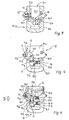
- number 10 designates, as a whole, a buckle for a safety belt with three branches, in particular for safety seats for children carried in motor vehicles and the like, according to the present invention.
- the said buckle 10 basically comprises (according to the subject of the Italian patent application for utility model No. T098U 000121 filed on June 30, 1998):
- the first tongue 11.1 has, at the free end of its shaft 11.10 (i.e., the distal end with respect to the fixing eyelet), a side notch 11.3, whilst the shaft 11.20 of the other tongue 11.2 is longer than the one of the tongue 11.1 and has its free end (i.e., the one distal with respect to the fixing eyelet) substantially shaped like a hook 11.4.
- the notch 11.3 of the first tongue is set facing outwards, whilst the second tongue 11.2 hooks from underneath, with its end 11.4, the first tongue 11.1.
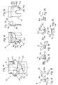
- the box-shaped locking casing 12 consists of a monolithic body, for example one made of a die-cast metal alloy.
- the said box-shaped locking casing 12 has three openings (Figures 7 and 11):
- the said second opening 12.3 provides, by means of two opposed straight walls, namely a top wall and a bottom wall ( Figure 11), rectilinear slide guides to enable sliding with play of a clamping member 13 ( Figures 7, 10, 17 and 18).
- the member 13 is shaped in part like a pawl 13.1, which is mobile in said opening 12.3 in the plane of the shafts 11.10, 11.20 of the tongues ( Figure 10), in a direction transverse to the direction of sliding of the shafts themselves during their insertion into the seat 12.2 through the opening 12.1, in such a way as to engage stably, following upon introduction of the shafts and also on account of the elastic action of a first spring member 14, said side notch 11.3 of the first tongue 11.1.
- Said first tongue 11.1 is thus kept firmly fixed against extraction, and, together with it, also the other tongue 11, with its end 11.4 hooked to the first tongue 11.1 (buckle-closed condition - Figures 1 and 8 to 10 - in which the safety belt is properly hitched).
- a release push-button 15 ( Figures 4, 5, 8, and 12-14) is slidably mounted externally with respect to said front wall 12.4 of the box-shaped locking casing 12, by means of guides 12.6 ( Figure 11) which are fixed integrally to the locking casing 12 itself, in a direction substantially parallel to the direction of introduction of the shafts 11.10, 11.20 of the tongues into the seat 12.2.
- the aforesaid push-button 15 has, in one of its sides 15.2, a recess 15.3 in which there is freely received a corresponding tab or finger 13.2 of the clamping member 13, said finger being fixed integrally to the pawl 13.1 but projecting outwards with respect to said second opening 12.3 and said front wall 12.4 of the box-shaped locking casing 12.
- expelling means 16 which are elastically urged and comprise a mobile block 16.1 ( Figures 19-21), which, when the shafts 11.10, 11.20 of the tongues are properly introduced into the seat 12.2, tends to slide into said opening 12.5 in a direction parallel to that of the shafts themselves and in a way that counters the action of a third spring member 16.2, which is thus elastically pre-loaded.
- the box-shaped locking casing 12 and the release push-button 15 constitute a structural and functional unit independent of the shell 11, which mainly has a function of coating.
- a rocking lever 17 (Figures 4, 6, 8, 9, 15, and 16), which is set between said finger 13.2 of the clamping member 13 and a front projection 16.3 of the mobile block 16.1, which protrudes with respect to a third opening 12.5 and to said front wall 12.4.
- Said lever 17 is hinged, at one of its ends and by means of an integral pivot 17.1 ( Figure 11), in a corresponding hole 12.7 of said front wall 12.4, in such a way that it can oscillate about an axis substantially orthogonal to the wall itself.
- said lever is set, with its other end 17.2 ( Figures 6 and 9), which is free, in contact with or in the proximity of said finger 13.2, whilst it has, in its intermediate part, a groove 17.3 which can engage, in an oscillated position of the lever about said axis, said front projection 16.3 ( Figures 8 and 9).
- An intermediate projection 17.4 protrudes at the front from said lever 17, whilst in an appendage 15.4 extending from the button 15 in a direction parallel to said front wall 12.4 and overlying both said finger 13.2 and said free end 17.2 of the lever 17, there is provided a basically V-shaped notch 17.5, which, with its straight inclined side 17.6 ( Figure 12) provides a cam surface that co-operates with said projection 17.4, which has the function of a cam follower.
- a side tab 15.5 which is co-planar and provided, at its free end, with a catch 15.6 ( Figures 4, 8, 12, and 14) extending towards said front wall 12.4 and having a chamfered side 15.7, so as to provide a surface inclined roughly at 45° with respect to the direction of sliding of the shafts of the tongues 11.1, 11.2 when the latter are properly set alongside one another with respect to the seat 12.2.
- the lever 17 is thus prevented from rotating and is kept oscillated about the axis of the pivot 17.1, so as to push said finger 13.2, integral with the pawl 13.1, to the end of travel in the resting position with respect to said second opening 12.3 (i.e., it is set back at the maximum distance from the seat 12.2 of the box-shaped locking casing 12).
- said block 16.1 of the expelling means 16 is elastically urged by said third spring member 16.2 into the end-of-travel position towards the seat 12.2, whilst with one of its sides it rests against the free end 17.2 of said lever 17.
- said finger 13.2 with the pawl 13.1 integral with it, is urged to slide as indicated on account of the combined action of the following: (1) said second spring member 15.1, which, by means of the sliding coupling of the opposed inclined sides 15.7 / 13.4 respectively of the catch 15.6 of the push-button 15 and of the groove 13.3 of the finger 13.2, indirectly urges said finger 13.2; and (2) said first spring member 14, which urges said finger 13.2 directly.
- Said lever 17 is thus made to describe an arc of rotation, overlying said projection 16.3 of the block 16.1.
- said pawl 13.1 slides as far as its end-of-travel in said second opening 12.3 towards said seat 12.2 and engages fully the side notch 11.3 of the tongue 11.1, which is properly inserted inside the seat 12.2 together with the other tongue 11.2, thus achieving the condition of correct and stable closing of the buckle 10.
- said finger 13.2, sliding integrally with the pawl 13.1 disengages the catch 15.6 and enables the push-button 15 to slide, urged by said second spring member 15.1, as far as its completely extended position with respect to the shell 11.
- said catch 15.6 sets itself immediately behind said finger 13.2 and consequently prevents even partial recession of the pawl 13.1 which is integral with said finger 13.2 (this arrangement prevents in a reliable way the problems linked to the so-called "inertial pull-out" of the buckle 10 - Figures 1 and 8 to 10).
- said catch 15.6, moving integrally with the push-button 15, is displaced with respect to the finger 13.2 and releases it; this enables the pawl 13.1 to perform its reverse travel of complete recession in said opening 12.3, disengaging the side notch 11.3 of the tongue 11.1, which is thus released together with the other tongue 11.2.
- the buckle 10 is thus opened, the tongues 11.1 and 11.2 extracted, and the release push-button 15 brought back into its resting position.
- said block 16.1 of the expelling means 16 has in a position set in front of said seat 12.2 of the box-shaped locking casing 12, two steps (respectively 16.4, 16.5 - Figures 10, 22 and 23), set in such a way that, when the shafts 11.10, 11.20 of the tongues 11.1, 11.2 are properly set alongside one another and inserted into said seat, their feet respectively rest on the one (11.10 / 16.4) and on the other (11.20 / 16.5) of said steps, whilst said tongues push said block in a way that counters the action of said third spring member 16.2 ( Figure 10).
- each of said steps 16.4, 16.5 has a resting surface of the respective foot of tongue shaped at least in part according to a curvilinear pattern degrading towards the inside of the block 16.1 itself, so that when just one tongue 11.1 or 11.2 is inserted into the seat 12.2 of the box-shaped locking casing 12, the foot of its shaft (which is not supported by the shaft of the other tongue set alongside) rests and slides on the respective step 16.4, 16.5 of the block 16.1, setting itself obliquely in said seat (as illustrated by dashed-and-dotted lines in Figures 22 and 23).
Landscapes
- Buckles (AREA)
- Automotive Seat Belt Assembly (AREA)
- Emergency Lowering Means (AREA)
Claims (6)
- Schnalle für einen Dreipunktsicherheitsgurt, insbesondere für Sicherheitskindersitze, die in Kraftfahrzeugen und dgl. mitgeführt werden, umfassend:- eine vorzugsweise aus Metall bestehende dosenförmige Schließe (12), die mit dem Ende eines Gurtbandabschnittes des Sicherheitsgurtes verbunden und in einer Schale (11) untergebracht ist;- zwei Zungen (11.1, 11. 2), die jeweils mit dem Ende eines entsprechenden der beiden anderen Gurtbandabschnitte des Sicherheitsgurtes verbunden und mit flachen Dornen (11.10, 11.20) versehen sind, die in die Schließe (12) einzuführen sind, wobei eine der Zungen (11.1) eine seitliche Einkerbung (11.3) aufweist;- eine in der dosenförmigen Schließe (12) eingebrachte Aufnahme (12.2), die mit einer ersten Öffnung (12.1) versehen ist, welche eine Führung zur korrekten Einführung und Herausnahme der ordnungsgemäß der Länge nach nebeneinander angeordneten Zungen in bzw, aus der Aufnahme selbst bildet;- ein Klemmelement (13) mit einer Klinke (13.1), die verschieblich in einer zweiten Öffnung (12.3) der dosenförmigen Schließe untergebracht ist und mit der Aufnahme (12.2) in Verbindung steht, um mit der seitlichen Einkerbung (11.3) einer der vollständig in die Aufnahme (12.2) eingeführten, der Länge nach nebeneinander angeordneten Zungen in Eingriff zu gelangen, um somit die Zungen gegen ein Herausziehen zu sichern (geschlossener Zustand der Schnalle);- ein Knopf (15) zum Lösen des Gurts, der mit Bezug auf die dosenförmige Schließe (12) verschieblich ist und durch elastische Mittel (15.1) belastet wird und in dem geschlossenen Zustand der Schnalle weiter von der Schale (11) vorsteht als in der geöffneten Position der Schnalle;- Auswurfmittel (16) mit einem Block (16.1), der in einer mit der Aufnahme (12.2) in Verbindung stehenden dritten Öffnung (12.5) der dosenförmigen Schließe (12) beweglich gelagert ist und durch andere elastische Mittel (16.2) so belastet wird, dass er in Richtung Aufnahme gleitet und der, wenn die Zungen in der Aufnahme derart eingeführt sind, dass sie ordnungsgemäß der Länge nach nebeneinander angeordnet sind, parallel zur Einführungsrichtung der Zungen entgegen der Kraft der anderen elastischen Mittel (16.2) verschoben wird,dadurch gekennzeichnet, dass sie folgendes umfasst:- einen Schwinghebel (17), der mit einem Ende (Zapfen 17.1) mit Bezug auf die dosenförmige Schließe (12) angelenkt ist und mit seinem gegenüber liegenden freien Ende (17.2) zwischen einem einstückig mit der Klinke (13. 1) der Klemmmittel (13) ausgebildeten Finger (13.2) und einem Vorsprung (16.3) des beweglichen Blocks (16.1) der Auswurfmittel (16) angeordnet ist, und der eine mittlere Nut (17.3) aufweist, die in einer verschwenkten Position des Hebels mit dem Vorsprung (16.3) des Blocks (16.1) und mit einem mittleren Vorsprung (17.4) in Eingriff gelangt; und- einen Fortsatz (15.4) des Knopfes (15), der sowohl über dem Finger (13.2) des Klemmmittels (13) als auch über dem freien Ende (17.2) des Hebels (17) liegt und mit einer in etwa V-förmigen Einkerbung (17.5) versehen ist, die eine geneigte gerade Seite (17.6) hat, die eine Nockenfläche bereitstellt, welche mit dem die Funktion eines Nockenstößels erfüllenden Vorsprung (17.4) des Hebels (17) zusammenwirkt,derart, dass:- bei geöffnetem Zustand der Schnalle (10) (gelöstem Gurt), der durch die elastischen Mittel (15.1) belastete Knopf (15) in der Ruheposition gehalten wird, in der der mittlere Vorsprung (17. 4) des Hebels (17) am Ende seines Weges in der V-förmigen Einkerbung (17.5) mit der Nockenfläche (17.6) in Eingriff gelangt; der Hebel (17) wird am Drehen gehindert und schwenkbar um die Achse seines eigenen Drehpunkts (Zapfen 17.1) derart gehalten, dass der Finger (13.2) bis an das Ende seines Weges in die Ruheposition mit Bezug auf die zweite Öffnung (12.3) gedrückt wird, und der Block (16.1) der Auswurfmittel (16) durch die anderen elastischen Mittel (16.2) elastisch in die Endposition Richtung Aufnahme (12.2) belastet wird, während er mit einer seiner Seiten an dem freien Ende (17.2) des Hebels (17) anliegt;während,- wenn die Dorne der ordnungsgemäß der Länge nach nebeneinander angeordneten Zungen (11.1, 11. 2) durch die erste Öffnung (12.1) in die Aufnahme (12.2) eingeführt sind, sie mit dem Block (16.1) in Eingriff gelangen und diesen entgegen der Kraft der anderen elastischen Mittel (16.2) in Kontakt mit dem freien Ende (17.2) des Hebels (17) verschieben, den sie in der oben genannten verschwenkten Position halten, wodurch die Klinke (13.1) daran gehindert wird, zu früh und daher fehlerhaft mit der seitlichen Einkerbung (11.3) einer (11,1) der in die Aufnahme (12.2) eingeführten Zungen (11.1) in Eingriff zu gelangen, und danach, während die Zungen weiter gleiten und wenn der Block (16.1) in etwa das Ende seines dem anderen elastischen Mittel (16.2) entgegenwirkenden Weges erreicht hat, sich der Block selbst in eine Position bringt, die der mittleren Nut (17.3) des Hebels (17) entspricht, wobei der Hebel, der nun nicht mehr daran gehindert wird, um die Achse seines eigenen Drehpunkts (Zapfens 17.1) zu schwenken, es dem Finger (13.2) ermöglicht, mit der einstückig damit ausgebildeten Klinke (13.1) in die Öffnung (12.3) in Richtung der in die Aufnahme (12.2) eingeführten Dorne der Zungen (11.1, 11.2) zu gleiten; wobei der Hebel (17) somit beim Drehen einen Bogen beschreibt, der über dem Vorsprung (16.3) des Blocks (16.1) liegt, während die Klinke (13.1) bis zum Ende ihres Weges in der zweiten Öffnung (12.3) in Richtung der Aufnahme (12.2) gleitet und vollständig in die seitliche Einkerbung (11.3) einer der Zungen eingreift, die ordnungsgemäß in der Aufnahme selbst eingeführt ist und somit der Zustand erreicht wird, in dem die Schnalle (10) korrekt und fest geschlossen ist; und umgekehrt,- wenn der Knopf (15) entgegen der Kraft der elastischen Mittel (15.1) gedrückt wird, seine Nockenfläche (17.6) mit dem mittleren Vorsprung (17.4) des Hebels (17) in Eingriff gelangt und dabei den Hebel in die umgekehrte Richtung um seinen Drehpunkt (Zapfen 17.1) verschwenkt; dieser Hebel (17) gibt somit den Block (16.1) der Auswurfmittel (16) frei, der, durch die anderen elastischen Mittel (16.2) belastet, die Zungen (11.1, 11.2) auf der Aufnahme (12.2) der dosenförmigen Schließe (12) herausdrückt; so wird die Schnalle (10) geöffnet, die Zungen (11.1, 11.2) herausgedrückt und der Knopf (15) zum Lösen des Gurts in seine Ruheposition zurückversetzt.
- Schnalle für einen Sicherheitsgurt nach Anspruch 1, dadurch gekennzeichnet, dass sie eine einstückig mit dem Knopf (15) ausgebildete Arretierung (15.6), die sich in Richtung der dosenförmigen Schließe (12) erstreckt und eine abgeschrägte Seite (15.7) aufweist, so dass eine Fläche entsteht, die mit Bezug auf die Gleitrichtung der Dorne der Zungen (11.1, 11.2) geneigt ist, wenn diese mit Bezug auf die Aufnahme (12.2) ordnungsgemäß der Länge nach nebeneinander liegen, sowie, im Endbereich des Fingers (13.2) des Klemmelements (13) gegenüber dem freien Ende (17.2) des Hebels (17), eine Nut (13. 3) mit einer in etwa parallel zur Seite (15.7) der Arretierung (15.6) ausgerichteten, geneigten Seite (13.4) umfasst, derart, dass,- wenn der durch die elastischen Mittel (15.1) belastete Knopf (15) in der Ruheposition gehalten wird, die Arretierung (15.6) in der Nut (13.3) des Fingers (13.2) aufgenommen wird, wodurch der Knopf selbst daran gehindert wird, unter der Einwirkung der elastischen Mittel (15.1) [geöffnete Schnalle] weiter aus der Schale (11) zu gleiten; während,- wenn der vorgenannte Finger (13.2) des Klemmelements (13) einstückig mit der Klinke (13.1) in Richtung Aufnahme (12.2) gleitet, er außer Eingriff mit der Arretierung (15.6) gelangt und ein Gleiten des von den elastischen Mitteln (15.1) belasteten Knopfs (15) zulässt, bis dieser seine vollständig ausgefahrene Position mit Bezug auf die Schale (11) erreicht [Schnalle geschlossen; Gurt angelegt] und in dem vorgenannten Zustand die Arretierung (15.6) unmittelbar hinter dem Finger (13.2) des Klemmelements (13) zu liegen kommt und selbst ein teilweises Zurückziehen der Klinke (13.1) verhindert (wobei diese Anordnung zuverlässig das Phänomen des Herausziehens aus der Schnalle (10) aufgrund der Trägheit verhindert); während,- wenn danach der Knopf (15) entgegen der Kraft der elastischen Mittel (15.1) gedrückt wird, die einstückig mit dem Knopf (15) sich bewegende Arretierung (15.6) mit Bezug auf den Finger (13.2) des Klemmelements (13) verschoben wird und diesen freigibt; dies ermöglicht es der Klinke (13.1), ihren Weg bis zu deren vollständigem Einliegen in der Öffnung (12.3) zurückzulegen, wobei sie außer Eingriff mit der seitlichen Einkerbung (11.3) der Zunge (11.1) gelangt, welche dadurch zusammen mit der anderen Zunge (11.2) freigegeben wird [offene Schnalle; Gurt gelöst].
- Schnalle für einen Sicherheitsgurt nach Anspruch 2, dadurch gekennzeichnet, dass der Finger (13.2) des Klemmelements (13) so belastet wird, dass er einstückig mit der Klinke (13.1) in Richtung Aufnahme (12.2) gleitet, wobei dies aufgrund der kombinierten Einwirkungen: (a) der elastischen Mittel (15.1), die mittels der gleitenden Kopplung der einander gegenüber liegenden Seiten (15.7 bzw. 13.4) der Arretierung (15.6) des Knopfes (15) und der Nut (13. 3) des Fingers (13.2) den Finger (13.2) mittelbar belasten; und (b) weiterer elastischer Mittel (14), die den Finger (13.2) unmittelbar belasten, geschieht.
- Schnalle für einen Sicherheitsgurt nach Anspruch 2 und 3, dadurch gekennzeichnet, dass der Weg, den die Klinke (13.1) beim Zurückziehen entgegen der unmittelbaren Kraft der weiteren elastischen Mittel (14) zurücklegt, durch die umgekehrte Verschwenkung des Hebels (17) bestimmt wird, dessen freies Ende (17.2) am Finger (13. 2) anliegt und gegen diesen gedrückt wird.
- Schnalle für einen Sicherheitsgurt nach Anspruch 1, dadurch gekennzeichnet, dass, in einer Position, in der er vor der Aufnahme (12.2) der dosenförmigen Schließe (12) angeordnet ist, der Block (16.1) der Auswurfmittel (16) zwei Stufen (16.4 bzw. 16.5) aufweist, die derart angeordnet sind, dass, wenn die Dorne der Zungen (11.1, 11.2) ordnungsgemäß der Länge nach nebeneinander liegen und in die Aufnahme eingeführt sind, deren Füße jeweils auf der einen (11.1 /16.4) und auf der anderen (11.2 /16.5)dieser Stufen aufliegen, während die Zungen den Block entgegen der Kraft der anderen elastischen Mittel (16.2) drücken.
- Schnalle für einen Sicherheitsgurt nach Anspruch 5, dadurch gekennzeichnet, dass jede der Stufen (16.4, 16.5) eine Auflagefläche für den jeweiligen Fuß der Zunge aufweist, welche mindestens teilweise einen bogenförmigen Verlauf aufweist, welcher in Richtung Inneres des Blocks (16.1) selbst abfällt, so dass, wenn nur eine Zunge (11.1 1 bzw. 11.2) in der Aufnahme (12.2) der dosenförmigen Schließe (12) eingeführt ist, der Fuß ihres Dorns auf der jeweiligen Stufe (16.4, 16.5) des Blocks (16.1) aufliegt und so gleitet, dass er schräg zur Aufnahme zu liegen kommt, und den Block (16.1) nicht in der Öffnung (12.5) entgegen der Kraft der anderen elastischen Mittel (16.2) verschiebt, so dass ein unerwünschtes fehlerhaftes Schließen der Schnalle (10) verhindert wird.
Priority Applications (6)
| Application Number | Priority Date | Filing Date | Title |
|---|---|---|---|
| AT01122789T ATE339905T1 (de) | 2001-09-21 | 2001-09-21 | Gurtschnalle für sicherheitsgurt mit drei zungen, insbesondere für kindersitze in kraftfahrzuege und dergleichen |
| ES01122789T ES2272392T3 (es) | 2001-09-21 | 2001-09-21 | Hebilla para cinturon de seguridad con tres correas, en particular para asiento de seguridad destinado a niños transportados en vehiculos a motor y similares. |
| DE60123239T DE60123239T2 (de) | 2001-09-21 | 2001-09-21 | Gurtschnalle für Sicherheitsgurt mit drei Zungen, insbesondere für Kindersitze in Kraftfahrzeugen und dergleichen |
| EP01122789A EP1295541B1 (de) | 2001-09-21 | 2001-09-21 | Gurtschnalle für Sicherheitsgurt mit drei Zungen, insbesondere für Kindersitze in Kraftfahrzuege und dergleichen |
| US10/217,542 US6694577B2 (en) | 2001-09-21 | 2002-08-14 | Buckle for safety belt with three branches, in particular for safety seats for children carried in motor vehicles and the like |
| JP2002275448A JP2003174906A (ja) | 2001-09-21 | 2002-09-20 | 3つの分岐部を有する安全ベルト用、特に自動車等に幼児を乗せて行くためのバックル |
Applications Claiming Priority (1)
| Application Number | Priority Date | Filing Date | Title |
|---|---|---|---|
| EP01122789A EP1295541B1 (de) | 2001-09-21 | 2001-09-21 | Gurtschnalle für Sicherheitsgurt mit drei Zungen, insbesondere für Kindersitze in Kraftfahrzuege und dergleichen |
Publications (2)
| Publication Number | Publication Date |
|---|---|
| EP1295541A1 EP1295541A1 (de) | 2003-03-26 |
| EP1295541B1 true EP1295541B1 (de) | 2006-09-20 |
Family
ID=8178698
Family Applications (1)
| Application Number | Title | Priority Date | Filing Date |
|---|---|---|---|
| EP01122789A Expired - Lifetime EP1295541B1 (de) | 2001-09-21 | 2001-09-21 | Gurtschnalle für Sicherheitsgurt mit drei Zungen, insbesondere für Kindersitze in Kraftfahrzuege und dergleichen |
Country Status (6)
| Country | Link |
|---|---|
| US (1) | US6694577B2 (de) |
| EP (1) | EP1295541B1 (de) |
| JP (1) | JP2003174906A (de) |
| AT (1) | ATE339905T1 (de) |
| DE (1) | DE60123239T2 (de) |
| ES (1) | ES2272392T3 (de) |
Families Citing this family (36)
| Publication number | Priority date | Publication date | Assignee | Title |
|---|---|---|---|---|
| US7073235B2 (en) * | 2003-06-17 | 2006-07-11 | Benedict Charles E | Non-inertial release safety restraint belt buckle systems |
| US7263749B2 (en) * | 2003-06-17 | 2007-09-04 | Tesseract International, Inc. | Non-inertial release safety restraint belt buckle system |
| ITTO20030486A1 (it) * | 2003-06-26 | 2004-12-27 | Claudia Cerruti | Dispositivo di aggancio per cinture di ritenuta, |
| US7520036B1 (en) | 2003-07-11 | 2009-04-21 | Amsafe Commercial Products, Inc. | Multi-point buckle for restraint system |
| JP4604482B2 (ja) * | 2003-12-18 | 2011-01-05 | タカタ株式会社 | チャイルドシート用トング及びチャイルドシート |
| USD519406S1 (en) | 2004-01-16 | 2006-04-25 | Merrill David T | Buckle with slide button |
| FR2876333B1 (fr) * | 2004-10-07 | 2006-12-29 | Valeo Electronique Sys Liaison | Boucle de ceinture de securite pour vehicule automobile |
| US7263750B2 (en) * | 2005-06-09 | 2007-09-04 | Amsafe, Inc. | Buckle assembly having single release for multiple belt connectors |
| US20090025616A1 (en) * | 2007-07-23 | 2009-01-29 | Amsafe, Inc. | Air cargo pallets having synthetic cores and associated systems and methods for manufacturing same |
| WO2009094404A1 (en) * | 2008-01-22 | 2009-07-30 | Amsafe Commercial Products, Inc. | Buckle assemblies and associated connectors for use with child seats and other restraint systems |
| US8303043B2 (en) * | 2008-09-29 | 2012-11-06 | Amsafe, Inc. (Phoenix Group) | Tensioning apparatuses for occupant restraint systems and associated systems and methods |
| US7904997B2 (en) | 2008-11-07 | 2011-03-15 | Amsafe, Inc. | Buckles for inflatable personal restraint systems and associated systems and methods |
| US8469401B2 (en) | 2009-02-23 | 2013-06-25 | Amsafe, Inc. | Seat harness pretensioner |
| US8469400B2 (en) * | 2009-02-23 | 2013-06-25 | Amsafe, Inc. (Phoenix Group) | Seat harness pretensioner |
| US8444222B2 (en) * | 2009-04-07 | 2013-05-21 | Amsafe Commercial Products, Inc. | Child safety seat attachment belt retractor system |
| CA2719846A1 (en) * | 2009-11-02 | 2011-05-02 | Amsafe Commercial Products, Inc. | Devices for adjusting tension in seat belts and other restraint system webs, and associated methods |
| US8683666B2 (en) | 2009-11-04 | 2014-04-01 | Amsafe Commercial Products, Inc. | Restraint system buckle components having tactile surfaces, and associated methods of use and manufacture |
| US8627554B1 (en) | 2010-05-03 | 2014-01-14 | Amsafe, Inc. (Phoenix Group) | Buckle assemblies with swivel and dual release features and associated methods of use and manufacture |
| US8777323B2 (en) | 2010-07-20 | 2014-07-15 | Amsafe, Inc. | Restraint harnesses and associated methods of use and manufacture |
| CN103140373B (zh) * | 2010-09-14 | 2016-05-25 | 赛贝克斯工业技术有限公司 | 儿童座椅 |
| USD655223S1 (en) | 2010-09-15 | 2012-03-06 | Amsafe Commercial Products, Inc. | Buckle assembly |
| USD661619S1 (en) | 2010-09-15 | 2012-06-12 | Amsafe Commercial Products, Inc. | Buckle assembly |
| CN103311469B (zh) * | 2012-03-12 | 2016-04-13 | 海洋王照明科技股份有限公司 | 电池盒的开合装置 |
| US9022483B2 (en) | 2012-06-07 | 2015-05-05 | Shield Restraint Systems, Inc. | Seatbelt buckle tongue assembly |
| US8656566B1 (en) * | 2012-11-08 | 2014-02-25 | Tung-Cheng Chen | Buckle of a seat belt |
| US9277788B2 (en) | 2013-02-19 | 2016-03-08 | Amsafe, Inc. | Dual release buckle assemblies and associated systems and methods |
| EP2958453A4 (de) | 2013-02-19 | 2016-07-27 | Amsafe Inc | Schnallenanordnungen mit hebeverschlüssen und zugehörige verfahren und systeme |
| US9775410B2 (en) | 2014-12-16 | 2017-10-03 | Shield Restraint Systems, Inc. | Web adjusters for use with restraint systems and associated methods of use and manufacture |
| US10604259B2 (en) | 2016-01-20 | 2020-03-31 | Amsafe, Inc. | Occupant restraint systems having extending restraints, and associated systems and methods |
| US9814282B2 (en) | 2016-02-02 | 2017-11-14 | Shield Restraint Systems, Inc. | Harsh environment buckle assemblies and associated systems and methods |
| US10611334B2 (en) | 2017-02-07 | 2020-04-07 | Shield Restraint Systems, Inc. | Web adjuster |
| CN107495542B (zh) * | 2017-06-23 | 2021-06-08 | 安庆市枞江汽车部件制造有限公司 | 一种具有高安全性能的汽车安全带卡扣组件 |
| US11273790B2 (en) | 2018-03-06 | 2022-03-15 | Shield Restraint Systems, Inc. | Height adjusters with anti-cinch features for occupant restraint systems |
| US10953847B2 (en) | 2018-03-06 | 2021-03-23 | Shield Restraint Systems | Height adjusters with anti-cinch features for occupant restraint systems |
| WO2019195373A1 (en) | 2018-04-04 | 2019-10-10 | Shield Restraint Systems, Inc. | Energy absorbing devices for use with webs |
| CN114701411B (zh) * | 2022-03-17 | 2023-06-20 | 安徽鸿贝智能科技有限公司 | 一种儿童座椅用保护带连接勾件 |
Family Cites Families (13)
| Publication number | Priority date | Publication date | Assignee | Title |
|---|---|---|---|---|
| US3523342A (en) * | 1968-01-22 | 1970-08-11 | John P Spires | Seat belt buckle latch |
| US3564672A (en) * | 1968-11-26 | 1971-02-23 | Mc Donnell Douglas Corp | Multiple harness strap quick release buckle |
| US3591902A (en) * | 1969-12-18 | 1971-07-13 | Allied Chem | Two-tongue buckle assembly |
| WO1985005258A1 (en) * | 1984-05-22 | 1985-12-05 | Holmberg Gote Eskil Yngve | Lock for safety belts |
| JPH0719285Y2 (ja) * | 1989-03-31 | 1995-05-10 | ワイケイケイ株式会社 | バックル |
| US5283933A (en) * | 1989-06-22 | 1994-02-08 | Indiana Mills & Manufacturing, Inc. | Belt buckle with interactive dual tongues |
| JPH0345711U (de) * | 1989-09-11 | 1991-04-26 | ||
| DE4215563A1 (de) * | 1992-05-12 | 1993-11-18 | Trw Repa Gmbh | Schloß für Fahrzeug-Sicherheitsgurtsysteme |
| DE4344023C2 (de) * | 1993-12-23 | 1995-11-09 | Locktec Gmbh Kinder Sicherheit | Verschluß für Sicherheitsgurte |
| US5522619A (en) * | 1995-02-01 | 1996-06-04 | Alliedsignal Inc. | End release seat belt buckle having an inertia-sensitive locking mechanism |
| GB9614623D0 (en) * | 1996-07-11 | 1996-09-04 | Alliedsignal Ltd | Buckle |
| IT236268Y1 (it) * | 1997-03-05 | 2000-08-08 | Rofin S R L | Fibbia di cintura di sicurezza a tre rami per seggiolini di sicurezzaper bambini trasportati su autoveicoli e simili |
| ES2156749B1 (es) * | 1999-08-10 | 2002-02-01 | Itw Espana Sa | Cierre de seguridad para sillas de niños y similares. |
-
2001
- 2001-09-21 DE DE60123239T patent/DE60123239T2/de not_active Expired - Lifetime
- 2001-09-21 ES ES01122789T patent/ES2272392T3/es not_active Expired - Lifetime
- 2001-09-21 EP EP01122789A patent/EP1295541B1/de not_active Expired - Lifetime
- 2001-09-21 AT AT01122789T patent/ATE339905T1/de not_active IP Right Cessation
-
2002
- 2002-08-14 US US10/217,542 patent/US6694577B2/en not_active Expired - Fee Related
- 2002-09-20 JP JP2002275448A patent/JP2003174906A/ja active Pending
Also Published As
| Publication number | Publication date |
|---|---|
| ATE339905T1 (de) | 2006-10-15 |
| US20030056346A1 (en) | 2003-03-27 |
| DE60123239T2 (de) | 2007-09-13 |
| ES2272392T3 (es) | 2007-05-01 |
| EP1295541A1 (de) | 2003-03-26 |
| DE60123239D1 (de) | 2006-11-02 |
| JP2003174906A (ja) | 2003-06-24 |
| US6694577B2 (en) | 2004-02-24 |
Similar Documents
| Publication | Publication Date | Title |
|---|---|---|
| US6694577B2 (en) | Buckle for safety belt with three branches, in particular for safety seats for children carried in motor vehicles and the like | |
| CA1178792A (en) | Safety belt buckle | |
| US5588189A (en) | Buckle for vehicle seat belt system | |
| CA1134599A (en) | Buckle with readily releasable latch | |
| US4317263A (en) | Belt lock for a safety belt | |
| US5996192A (en) | Buckle assembly | |
| US5606783A (en) | Buckle for vehicle seat belt system | |
| US5283933A (en) | Belt buckle with interactive dual tongues | |
| US5526556A (en) | Buckle for vehicle seat | |
| EP1266587B1 (de) | Sicherheitsgurtschloss | |
| JP2587877Y2 (ja) | シートベルト用バックル装置 | |
| CA1315958C (en) | Buckle assembly | |
| EP1224880B1 (de) | Sicherheitsschnalle für kindersitze | |
| EP1641366A1 (de) | Verschlusseinrichtung für sicherheitsgurte insbesondere für sicherheitssitze für kinder in kraftfahrzeugen | |
| JPH08256809A (ja) | バックル | |
| US4575907A (en) | Latch buckle for seat belt | |
| US8938865B2 (en) | Buckle for restraint belts, particularly for car safety seats for children | |
| GB2166187A (en) | Seat belt latch buckle | |
| US5216788A (en) | Impact-protected safety belt buckle | |
| EP0867131B1 (de) | Schnalle für einen Dreitrum-Sicherheitsgurt an Sicherheitssitzen für in Kraftfahrzeugen u.dgl. mitgeführte Kinder | |
| JP3652766B2 (ja) | バックル | |
| EP0043239B1 (de) | Zungen- und Schnallenbefestigung für Sicherheitsgurte | |
| KR101258095B1 (ko) | 충격 흡수용 안전 벨트 버클 | |
| ITTO20000110U1 (it) | Fibbia di cintura di sicurezza a tre rami, in particolare per seggiolini di sicurezza per bambini trasportati su autoveicoli e simili. | |
| KR100436094B1 (ko) | 헬멧 턱끈용 버클 |
Legal Events
| Date | Code | Title | Description |
|---|---|---|---|
| PUAI | Public reference made under article 153(3) epc to a published international application that has entered the european phase |
Free format text: ORIGINAL CODE: 0009012 |
|
| AK | Designated contracting states |
Kind code of ref document: A1 Designated state(s): AT BE CH CY DE DK ES FI FR GB GR IE IT LI LU MC NL PT SE TR |
|
| AX | Request for extension of the european patent |
Extension state: AL LT LV MK RO SI |
|
| 17P | Request for examination filed |
Effective date: 20030915 |
|
| AKX | Designation fees paid |
Designated state(s): AT BE CH CY DE DK ES FI FR GB GR IE IT LI LU MC NL PT SE TR |
|
| AXX | Extension fees paid |
Extension state: AL Payment date: 20030915 Extension state: RO Payment date: 20030915 |
|
| GRAP | Despatch of communication of intention to grant a patent |
Free format text: ORIGINAL CODE: EPIDOSNIGR1 |
|
| GRAS | Grant fee paid |
Free format text: ORIGINAL CODE: EPIDOSNIGR3 |
|
| GRAA | (expected) grant |
Free format text: ORIGINAL CODE: 0009210 |
|
| AK | Designated contracting states |
Kind code of ref document: B1 Designated state(s): AT BE CH CY DE DK ES FI FR GB GR IE IT LI LU MC NL PT SE TR |
|
| AX | Request for extension of the european patent |
Extension state: AL RO |
|
| PG25 | Lapsed in a contracting state [announced via postgrant information from national office to epo] |
Ref country code: LI Free format text: LAPSE BECAUSE OF FAILURE TO SUBMIT A TRANSLATION OF THE DESCRIPTION OR TO PAY THE FEE WITHIN THE PRESCRIBED TIME-LIMIT Effective date: 20060920 Ref country code: BE Free format text: LAPSE BECAUSE OF FAILURE TO SUBMIT A TRANSLATION OF THE DESCRIPTION OR TO PAY THE FEE WITHIN THE PRESCRIBED TIME-LIMIT Effective date: 20060920 Ref country code: AT Free format text: LAPSE BECAUSE OF FAILURE TO SUBMIT A TRANSLATION OF THE DESCRIPTION OR TO PAY THE FEE WITHIN THE PRESCRIBED TIME-LIMIT Effective date: 20060920 Ref country code: CH Free format text: LAPSE BECAUSE OF FAILURE TO SUBMIT A TRANSLATION OF THE DESCRIPTION OR TO PAY THE FEE WITHIN THE PRESCRIBED TIME-LIMIT Effective date: 20060920 |
|
| REG | Reference to a national code |
Ref country code: GB Ref legal event code: FG4D |
|
| PG25 | Lapsed in a contracting state [announced via postgrant information from national office to epo] |
Ref country code: IE Free format text: LAPSE BECAUSE OF NON-PAYMENT OF DUE FEES Effective date: 20060921 |
|
| PG25 | Lapsed in a contracting state [announced via postgrant information from national office to epo] |
Ref country code: MC Free format text: LAPSE BECAUSE OF NON-PAYMENT OF DUE FEES Effective date: 20060930 |
|
| REG | Reference to a national code |
Ref country code: CH Ref legal event code: EP |
|
| REG | Reference to a national code |
Ref country code: IE Ref legal event code: FG4D |
|
| REF | Corresponds to: |
Ref document number: 60123239 Country of ref document: DE Date of ref document: 20061102 Kind code of ref document: P |
|
| REG | Reference to a national code |
Ref country code: SE Ref legal event code: TRGR |
|
| PG25 | Lapsed in a contracting state [announced via postgrant information from national office to epo] |
Ref country code: DK Free format text: LAPSE BECAUSE OF FAILURE TO SUBMIT A TRANSLATION OF THE DESCRIPTION OR TO PAY THE FEE WITHIN THE PRESCRIBED TIME-LIMIT Effective date: 20061220 |
|
| PG25 | Lapsed in a contracting state [announced via postgrant information from national office to epo] |
Ref country code: PT Free format text: LAPSE BECAUSE OF FAILURE TO SUBMIT A TRANSLATION OF THE DESCRIPTION OR TO PAY THE FEE WITHIN THE PRESCRIBED TIME-LIMIT Effective date: 20070312 |
|
| REG | Reference to a national code |
Ref country code: CH Ref legal event code: PL |
|
| ET | Fr: translation filed | ||
| REG | Reference to a national code |
Ref country code: ES Ref legal event code: FG2A Ref document number: 2272392 Country of ref document: ES Kind code of ref document: T3 |
|
| PLBE | No opposition filed within time limit |
Free format text: ORIGINAL CODE: 0009261 |
|
| STAA | Information on the status of an ep patent application or granted ep patent |
Free format text: STATUS: NO OPPOSITION FILED WITHIN TIME LIMIT |
|
| 26N | No opposition filed |
Effective date: 20070621 |
|
| PG25 | Lapsed in a contracting state [announced via postgrant information from national office to epo] |
Ref country code: GR Free format text: LAPSE BECAUSE OF FAILURE TO SUBMIT A TRANSLATION OF THE DESCRIPTION OR TO PAY THE FEE WITHIN THE PRESCRIBED TIME-LIMIT Effective date: 20061221 |
|
| PG25 | Lapsed in a contracting state [announced via postgrant information from national office to epo] |
Ref country code: LU Free format text: LAPSE BECAUSE OF NON-PAYMENT OF DUE FEES Effective date: 20060921 Ref country code: TR Free format text: LAPSE BECAUSE OF FAILURE TO SUBMIT A TRANSLATION OF THE DESCRIPTION OR TO PAY THE FEE WITHIN THE PRESCRIBED TIME-LIMIT Effective date: 20060920 |
|
| PG25 | Lapsed in a contracting state [announced via postgrant information from national office to epo] |
Ref country code: CY Free format text: LAPSE BECAUSE OF FAILURE TO SUBMIT A TRANSLATION OF THE DESCRIPTION OR TO PAY THE FEE WITHIN THE PRESCRIBED TIME-LIMIT Effective date: 20060920 |
|
| PG25 | Lapsed in a contracting state [announced via postgrant information from national office to epo] |
Ref country code: IT Free format text: LAPSE BECAUSE OF NON-PAYMENT OF DUE FEES Effective date: 20100921 |
|
| PGRI | Patent reinstated in contracting state [announced from national office to epo] |
Ref country code: IT Effective date: 20110616 |
|
| PGFP | Annual fee paid to national office [announced via postgrant information from national office to epo] |
Ref country code: SE Payment date: 20120925 Year of fee payment: 12 Ref country code: GB Payment date: 20120924 Year of fee payment: 12 Ref country code: FI Payment date: 20120921 Year of fee payment: 12 |
|
| PGFP | Annual fee paid to national office [announced via postgrant information from national office to epo] |
Ref country code: IT Payment date: 20120920 Year of fee payment: 12 Ref country code: ES Payment date: 20120920 Year of fee payment: 12 |
|
| PGFP | Annual fee paid to national office [announced via postgrant information from national office to epo] |
Ref country code: DE Payment date: 20121107 Year of fee payment: 12 Ref country code: FR Payment date: 20121008 Year of fee payment: 12 |
|
| PGFP | Annual fee paid to national office [announced via postgrant information from national office to epo] |
Ref country code: NL Payment date: 20120928 Year of fee payment: 12 |
|
| REG | Reference to a national code |
Ref country code: NL Ref legal event code: V1 Effective date: 20140401 |
|
| REG | Reference to a national code |
Ref country code: SE Ref legal event code: EUG |
|
| PG25 | Lapsed in a contracting state [announced via postgrant information from national office to epo] |
Ref country code: FI Free format text: LAPSE BECAUSE OF NON-PAYMENT OF DUE FEES Effective date: 20130921 Ref country code: SE Free format text: LAPSE BECAUSE OF NON-PAYMENT OF DUE FEES Effective date: 20130922 |
|
| GBPC | Gb: european patent ceased through non-payment of renewal fee |
Effective date: 20130921 |
|
| REG | Reference to a national code |
Ref country code: DE Ref legal event code: R119 Ref document number: 60123239 Country of ref document: DE Effective date: 20140401 |
|
| REG | Reference to a national code |
Ref country code: FR Ref legal event code: ST Effective date: 20140530 |
|
| PG25 | Lapsed in a contracting state [announced via postgrant information from national office to epo] |
Ref country code: GB Free format text: LAPSE BECAUSE OF NON-PAYMENT OF DUE FEES Effective date: 20130921 |
|
| PG25 | Lapsed in a contracting state [announced via postgrant information from national office to epo] |
Ref country code: DE Free format text: LAPSE BECAUSE OF NON-PAYMENT OF DUE FEES Effective date: 20140401 Ref country code: NL Free format text: LAPSE BECAUSE OF NON-PAYMENT OF DUE FEES Effective date: 20140401 Ref country code: FR Free format text: LAPSE BECAUSE OF NON-PAYMENT OF DUE FEES Effective date: 20130930 Ref country code: IT Free format text: LAPSE BECAUSE OF NON-PAYMENT OF DUE FEES Effective date: 20130921 |
|
| REG | Reference to a national code |
Ref country code: ES Ref legal event code: FD2A Effective date: 20141007 |
|
| PG25 | Lapsed in a contracting state [announced via postgrant information from national office to epo] |
Ref country code: ES Free format text: LAPSE BECAUSE OF NON-PAYMENT OF DUE FEES Effective date: 20130922 |