EP1295782A2 - Verschlussdeckel für ein Bearbeitungsloch in einem Aluminiumblech - Google Patents
Verschlussdeckel für ein Bearbeitungsloch in einem Aluminiumblech Download PDFInfo
- Publication number
- EP1295782A2 EP1295782A2 EP02019691A EP02019691A EP1295782A2 EP 1295782 A2 EP1295782 A2 EP 1295782A2 EP 02019691 A EP02019691 A EP 02019691A EP 02019691 A EP02019691 A EP 02019691A EP 1295782 A2 EP1295782 A2 EP 1295782A2
- Authority
- EP
- European Patent Office
- Prior art keywords
- spring
- plate
- aluminum sheet
- spring plate
- edge
- Prior art date
- Legal status (The legal status is an assumption and is not a legal conclusion. Google has not performed a legal analysis and makes no representation as to the accuracy of the status listed.)
- Granted
Links
Images


Classifications
-
- B—PERFORMING OPERATIONS; TRANSPORTING
- B62—LAND VEHICLES FOR TRAVELLING OTHERWISE THAN ON RAILS
- B62D—MOTOR VEHICLES; TRAILERS
- B62D25/00—Superstructure or monocoque structure sub-units; Parts or details thereof not otherwise provided for
- B62D25/24—Superstructure sub-units with access or drainage openings having movable or removable closures; Sealing means therefor
-
- F—MECHANICAL ENGINEERING; LIGHTING; HEATING; WEAPONS; BLASTING
- F16—ENGINEERING ELEMENTS AND UNITS; GENERAL MEASURES FOR PRODUCING AND MAINTAINING EFFECTIVE FUNCTIONING OF MACHINES OR INSTALLATIONS; THERMAL INSULATION IN GENERAL
- F16B—DEVICES FOR FASTENING OR SECURING CONSTRUCTIONAL ELEMENTS OR MACHINE PARTS TOGETHER, e.g. NAILS, BOLTS, CIRCLIPS, CLAMPS, CLIPS OR WEDGES; JOINTS OR JOINTING
- F16B11/00—Connecting constructional elements or machine parts by sticking or pressing them together, e.g. cold pressure welding
- F16B11/006—Connecting constructional elements or machine parts by sticking or pressing them together, e.g. cold pressure welding by gluing
-
- F—MECHANICAL ENGINEERING; LIGHTING; HEATING; WEAPONS; BLASTING
- F16—ENGINEERING ELEMENTS AND UNITS; GENERAL MEASURES FOR PRODUCING AND MAINTAINING EFFECTIVE FUNCTIONING OF MACHINES OR INSTALLATIONS; THERMAL INSULATION IN GENERAL
- F16B—DEVICES FOR FASTENING OR SECURING CONSTRUCTIONAL ELEMENTS OR MACHINE PARTS TOGETHER, e.g. NAILS, BOLTS, CIRCLIPS, CLAMPS, CLIPS OR WEDGES; JOINTS OR JOINTING
- F16B21/00—Means for preventing relative axial movement of a pin, spigot, shaft or the like and a member surrounding it; Stud-and-socket releasable fastenings
- F16B21/02—Releasable fastening devices locking by rotation
Definitions
- the invention relates to a lid for permanently closing an oval-shaped Machining hole in an aluminum sheet through an adhesive connection.
- the lid consists of a circular aluminum plate with a concentric one Lid edge and a strip applied in a ring inside the lid edge made of meltable adhesive.
- the car bodies made of aluminum have a large number of machining holes, that after use through appropriately large lids must be closed again.
- To seal the holes splashproof it makes sense to use a cover made from the same aluminum material to be glued around the hole using a meltable adhesive. It is it is necessary that the adhesive strip applied inside the lid edge about 0.5 to 0.7 mm higher than the edge of the lid. Besides, it is for the sake of Saving energy and time expedient when the gluing process in connection with the catalytic dip painting of the aluminum body is carried out.
- the heating process after the immersion bath can melt at the same time and curing the adhesive.
- the lid is firmly around the hole on the aluminum plate pressed on and held until the adhesive has hardened.
- the outer edge in its contour of the shape of the oval machining hole corresponds and is slightly smaller than the edge of the hole that in the more distant Edge areas of the spring plate at a distance from its outer edge quarter-circle-shaped, spring-loaded spring tongues are stamped at their free ends and that after inserting the spring plate into the machining hole until the Adhesive strip on the aluminum sheet through the spring plate with its spring tongues a quarter turn of the cover plate on the back of the aluminum sheet Spring force can be brought firmly to the system.
- the lid designed according to the invention can be inserted into the The underside of the spring plate, which is mounted on the cover in a rotationally fixed manner, into the processing hole a 90 ° rotation in the machining hole quickly and easily, the lid is held firmly in contact with the sheet metal by the spring tongues. Since there is no immersion bath liquid in the subsequent catalytic immersion bath painting can get between the surfaces to be glued, after the Melting and curing of the adhesive in the subsequent heating process easily achieved a secure connection, which also through the spring tongues is mechanically secured, i.e. remains resistant even when subjected to stress.
- the closure lid shown in the figures consists of a circular cover plate 1 made of aluminum with a concentrically flanged cover edge 2 , which is used for flush support on the aluminum sheet 8 , and of a spring plate 5 which can be connected to the cover plate 1 in a rotationally fixed manner and which, after insertion into the processing hole 7 and the protruding adhesive strip 3 can be brought to bear on the aluminum sheet 8 by a quarter turn on the rear side thereof.
- a strip 3 of meltable adhesive is applied in an annular manner, to such a height that this strip 3 projects beyond the edge of the lid 2 by approximately 0.5 to 0.7 mm.
- a plane-parallel extension 4 is pressed or formed, which serves to support the spring plate 5 .
- the distance a between the attachment surface 4 and the lid edge 2 is somewhat larger than the thickness d of the aluminum sheet 8 to be covered by the lid plate 1 (see FIG. 8 ).
- the outer edge 6 of the spring plate 5 shown in Figures 3 and 4 has a contour which corresponds to the shape of the oval machining hole 7 shown in Figure 11 in the aluminum sheet 8 and is slightly smaller than the hole edge 9 of the machining hole 7.
- Edge regions 10 of the spring plate 5 are punched out approximately at a quarter-circular spring tongues 11 at a distance from its outer edge 6 . These are integrally formed on the spring plate 5 at one end.
- beads 12 are pronounced in the direction of the cover plate 1 , which slide when the spring plate 5 is screwed into the machining hole 7 over the aluminum sheet 8 and thereby generate the pretension ( FIG. 14 ).
- hemispherical knobs can also be pronounced
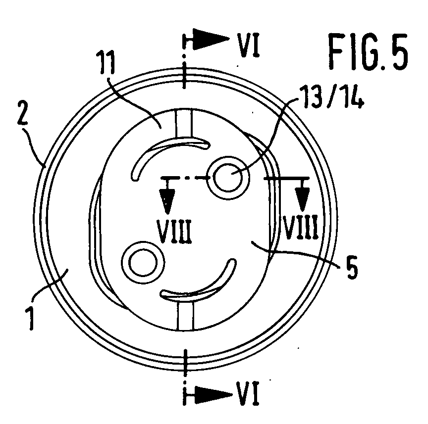
- At least two holes 13 are formed in the attachment surface 4 of the cover plate 1 and the spring plate 5 has the same number of bores 14 at the same distance from one another, which holes are intended to rivet the cover plate 1 to the spring plate 5 or to join them together 4 is preferably formed with mutually parallel inner walls 15 which serve as engagement surfaces for a correspondingly shaped diamond-shaped head of a turning tool and at the same time as a limitation for the quarter turn.
- the rotationally fixed connection between the spring plate 5 and the attachment surface 4 can advantageously also be produced by a so-called throughput joining process ( FIG. 8 ).
- the resulting recesses 16 in the attachment surface 4 can then also be used as engagement surfaces for a turning tool provided with corresponding pins.
- FIGS. 12 to 14 show the individual stages of the pre-assembly of the sealing cover on the aluminum sheet.
- FIG. 12 shows the closure cover before the spring plate 5 is inserted in the direction of arrow “E” into the oval machining hole 7 , which can be seen in a plan view in FIG. 11 .
- the closure cover is rotated by 90 ° in the arrow direction "D” by means of a tool which engages in the recess of the attachment 4 ,
- the spring tongues 11 run with their beads or knobs 12 at the resilient ends over the back of the aluminum sheet 8 and generate the required pretension on the adhesive strips 3 (FIG. 14) in the direction of arrow " F " by means of the spring force exerted by the spring tongues 11 .
- the cover is now firmly seated in the processing hole 7 and can start the furnace journey together with the aluminum sheet 8 by a so-called catalytic dip coating.
- the adhesive strip 3 melts due to the pressure prevailing in the oven temperature of to ° to 200 C and forms after curing with the aluminum sheet 8 around the machining hole 7 a waterproof connection while the cap is now after the melting of the adhesive strip 3 with the lid rim 2 rests on the aluminum sheet 8 .
Landscapes
- Engineering & Computer Science (AREA)
- Chemical & Material Sciences (AREA)
- Combustion & Propulsion (AREA)
- Transportation (AREA)
- Mechanical Engineering (AREA)
- Containers Opened By Tearing Frangible Portions (AREA)
- Closures For Containers (AREA)
- Gas Exhaust Devices For Batteries (AREA)
- Pressure Vessels And Lids Thereof (AREA)
- Polishing Bodies And Polishing Tools (AREA)
- Laminated Bodies (AREA)
- Gasket Seals (AREA)
Abstract
Description
- Fig. 1
- Die Deckelplatte des erfindungsgemäßen Verschlußdeckels in einer Draufsicht,
- Fig. 2
- einen Schnitt durch die Deckelplatte gemäß Linie II-II in Fig. 1,
- Fig. 3
- die zugehörige Federplatte in einer Draufsicht,
- Fig. 4
- die Federplatte in Seitenansicht,
- Fig. 5
- den einsatzbereiten Verschlußdeckel von unten gesehen,
- Fig. 6
- den Verschlußdeckel im Schnitt gemäß Linie VI-VI in Fig. 5,
- Fig. 7
- einen Teilschnitt durch die Federzunge gemäß Linie VII-VII in Fig. 3,
- Fig. 8
- einen Teilschnitt durch die Verbindungsstelle gemäß Linie VIII-VIII in Fig. 5 nach dem Durchsatzfügeprozess
- Fig. 9
- den Verschlußdeckel in perspektivischer Ansicht von unten,
- Fig. 10
- den Verschlußdeckel in perspektivischer Ansicht von oben,
- Fig. 11
- das ovale Bearbeitungsloch in einer Draufsicht,
- Fig. 12
- den Verschlußdeckel vor dem Einführen der Federplatte in das Bearbeitungsloch,
- Fig. 13
- den Verschlußdeckel nach dem Einführen der Federplatte in das Bearbeitungsloch und
- Fig. 14
- den im Bearbeitungsloch verriegelten Verschlußdeckel nach einer Drehung um 90°
Claims (7)
- Deckel zum dauerhaften Verschließen eines oval ausgebildeten Bearbeitungsloches (7) in einem Aluminiumblech (8) durch eine Klebeverbindung, bestehend aus einer kreisrunden Deckelplatte (1) aus Aluminium mit einem konzentrischen Deckelrand (2) und einem innerhalb des Deckelrandes (2) ringförmig aufgetragenen Streifen (3) aus aufschmelzbarem Klebstoff, dadurch gekennzeichnet, dass der Innenbereich der Deckelplatte (1) im Abstand der Dicke des Aluminiumblechs (8) mit einer planparallel zur Deckelplatte (1) ausgerichteten Federplatte (5) verbunden ist, deren Außenrand (6) in seiner Kontur der Form des ovalen Bearbeitungsloches (7) entspricht und etwas kleiner ist als der Lochrand (9), dass in den voneinander entfernteren Randbereichen (10) der Federplatte (5) im Abstand zu ihrem Außenrand (6) viertelkreisförmige, an ihren freien Enden auffederbare Federzungen (11) eingestanzt sind und dass nach dem Einführen der Federplatte (5) in das Bearbeitungsloch (7) bis zum Aufliegen des Klebestreifens (3) auf dem Aluminiumblech (8) die Federplatte (5) mit ihren Federzungen (11) durch eine Vierteldrehung der Deckelplatte (1) auf der Rückseite des Aluminiumblechs (8) durch Federkraft fest zur Anlage bringbar ist.
- Verschlußdeckel nach Anspruch 2, dadurch gekennzeichnet, daß am anderen, auffederbaren Ende der Federzungen (11) Wulste oder Noppen (12) in Richtung auf die Deckelplatte (1) eingeprägt sind.
- Verschlußdeckel nach einem der Ansprüche 1 bis 3, dadurch gekennzeichnet, daß in seinem mittleren Bereich ein planparalleler Ansatz (4) zur Auflage für die Federplatte (5) angeformt ist, wobei der Abstand a zwischen der Ansatzfläche (4) und dem Deckelrand (2) etwas größer als die Dicke d des Aluminiumbleches (8) ist.
- Verschlußdeckel nach Anspruch 4, dadurch gekennzeichnet, daß in der Ansatzfläche (4) mindestens zwei Löcher (13) eingeformt sind und die Federplatte (5) im gleichen Abstand zueinander die gleiche Anzahl Bohrungen (14) zur gegenseitigen Vemietung oder Fügung aufweist.
- Verschlußdeckel nach Anspruch 4, dadurch gekennzeichnet, daß die Deckelplatte (1) aus einem Aluminiumblech von etwa gleicher Stärke wie das abzudeckende Aluminiumblech (8) gefertigt ist und daß der planparallele Ansatz (4) mit zueinander parallelen Innenwänden (15) ausgeformt ist, welche als Angriffsflächen für ein entsprechend geformtes Drehwerkzeug und zugleich als Begrenzung für die Vierteldrehung dienen.
- Verschlußdeckel nach Anspruch 4, dadurch gekennzeichnet, daß die Verbindung zwischen der Federplatte (5) und der Ansatzfläche (4) durch einen Durchsatzfügeprozess hergestellt ist.
- Verschlußdeckel nach Anspruch 7, dadurch gekennzeichnet, daß die beim Durchsatzfügen entstehenden Vertiefungen (16) auf der Rückseite der Ansatzfläche (4) als Angriffspunkte für ein mit entsprechenden Stiften versehenes Drehwerkzeug verwendet werden.
Applications Claiming Priority (2)
| Application Number | Priority Date | Filing Date | Title |
|---|---|---|---|
| DE10146419 | 2001-09-20 | ||
| DE10146419A DE10146419B4 (de) | 2001-09-20 | 2001-09-20 | Verschlußdeckel für ein Bearbeitungsloch in einem Aluminiumblech |
Publications (3)
| Publication Number | Publication Date |
|---|---|
| EP1295782A2 true EP1295782A2 (de) | 2003-03-26 |
| EP1295782A3 EP1295782A3 (de) | 2003-12-17 |
| EP1295782B1 EP1295782B1 (de) | 2005-05-04 |
Family
ID=7699701
Family Applications (1)
| Application Number | Title | Priority Date | Filing Date |
|---|---|---|---|
| EP02019691A Expired - Lifetime EP1295782B1 (de) | 2001-09-20 | 2002-09-04 | Verschlussdeckel für ein Bearbeitungsloch in einem Aluminiumblech |
Country Status (6)
| Country | Link |
|---|---|
| US (1) | US6886712B2 (de) |
| EP (1) | EP1295782B1 (de) |
| AT (1) | ATE294728T1 (de) |
| CZ (1) | CZ20023157A3 (de) |
| DE (2) | DE10146419B4 (de) |
| ES (1) | ES2241935T3 (de) |
Cited By (1)
| Publication number | Priority date | Publication date | Assignee | Title |
|---|---|---|---|---|
| WO2016202318A1 (de) * | 2015-06-19 | 2016-12-22 | Kiekert Ag | Kraftfahrzeugtürverschluss |
Families Citing this family (6)
| Publication number | Priority date | Publication date | Assignee | Title |
|---|---|---|---|---|
| US9296467B1 (en) * | 2009-06-09 | 2016-03-29 | The Boeing Company | Pressure test door for use with a fuel tank |
| JP6122336B2 (ja) * | 2013-04-22 | 2017-04-26 | 大和化成工業株式会社 | ホールプラグ |
| US10738815B2 (en) * | 2016-09-28 | 2020-08-11 | Theodore Garfield | Swivel anchor with prevention of anchor arm retraction |
| DE102018207850B4 (de) * | 2018-05-18 | 2020-06-18 | Tesa Se | Stanzling zum dauerhaften Verschließen von Löchern |
| DE102021210855A1 (de) | 2021-09-28 | 2023-03-30 | Volkswagen Aktiengesellschaft | Abdeckungsanordnung und Verfahren zur Herstellung einer Kraftfahrzeugkarosserie unter Bildung einer Abdeckungsanordnung |
| CN114229044B (zh) * | 2021-11-18 | 2023-07-25 | 北京卫星制造厂有限公司 | 回转体防热套装制备方法 |
Family Cites Families (18)
| Publication number | Priority date | Publication date | Assignee | Title |
|---|---|---|---|---|
| DE179744C (de) * | ||||
| DE854159C (de) * | 1951-05-18 | 1952-10-30 | Karosseriewerke Drauz K G | Aus Blech hergestellte Verschlusskappe |
| US3851794A (en) * | 1970-09-01 | 1974-12-03 | Itw Ateco Gmbh | An expansible holeplug with seal |
| GB1468365A (en) * | 1973-11-14 | 1977-03-23 | United Carr Ltd | Plut or closure |
| US4094436A (en) * | 1975-01-22 | 1978-06-13 | Trw Inc. | Aperture plug |
| DE2541607C2 (de) * | 1975-09-18 | 1983-09-29 | Itw-Ateco Gmbh, 2000 Norderstedt | Abdeckteil zum Verschließen von Blechöffnungen |
| FR2452650A1 (fr) * | 1979-03-28 | 1980-10-24 | Itw De France | Procede et dispositif d'obturation etanche pour trous, orifices et ouvertures pratiques dans des panneaux |
| GB2067253A (en) * | 1980-01-11 | 1981-07-22 | United Carr Ltd | Aperture plug |
| US4391384A (en) * | 1981-12-14 | 1983-07-05 | Dan T. Moore Co. | Automobile body panel hole closure |
| US4494671A (en) * | 1984-01-12 | 1985-01-22 | The Dan T. Moore Co. | Automobile body panel hole closure |
| US4560083A (en) * | 1984-01-16 | 1985-12-24 | Trw Inc. | Closure and method for an aperture |
| DE3427626C1 (de) * | 1984-07-26 | 1985-10-17 | TRW United-Carr GmbH, 6000 Frankfurt | Verschlussdeckel |
| DE3442109C2 (de) * | 1984-11-17 | 1993-10-21 | Itw Ateco Gmbh | Einteilig geformtes Abdeckteil zum Verschließen von Blechöffnungen |
| US4817262A (en) * | 1985-11-04 | 1989-04-04 | Perfection Spring & Stamping Corp. | Paint drain closure attaching method |
| JPH0614085Y2 (ja) * | 1988-12-03 | 1994-04-13 | 株式会社ニフコ | パネル状部品の固定用クリップ |
| FR2682072B1 (fr) * | 1991-10-04 | 1997-04-18 | Itw De France | Obturateur a souder par collage pour ouverture pratiquee dans une tole, notamment de carrosserie automobile. |
| FR2707233B1 (fr) * | 1993-07-05 | 1995-10-06 | Itw De France | Obturateur à souder par collage pour une ouverture pratiquée dans une tôle. |
| US5505324A (en) * | 1995-05-26 | 1996-04-09 | Trw, Inc. | Hole closure |
-
2001
- 2001-09-20 DE DE10146419A patent/DE10146419B4/de not_active Expired - Fee Related
-
2002
- 2002-09-04 ES ES02019691T patent/ES2241935T3/es not_active Expired - Lifetime
- 2002-09-04 DE DE50202983T patent/DE50202983D1/de not_active Expired - Fee Related
- 2002-09-04 EP EP02019691A patent/EP1295782B1/de not_active Expired - Lifetime
- 2002-09-04 AT AT02019691T patent/ATE294728T1/de not_active IP Right Cessation
- 2002-09-19 CZ CZ20023157A patent/CZ20023157A3/cs unknown
- 2002-09-19 US US10/247,236 patent/US6886712B2/en not_active Expired - Fee Related
Cited By (1)
| Publication number | Priority date | Publication date | Assignee | Title |
|---|---|---|---|---|
| WO2016202318A1 (de) * | 2015-06-19 | 2016-12-22 | Kiekert Ag | Kraftfahrzeugtürverschluss |
Also Published As
| Publication number | Publication date |
|---|---|
| US20030052132A1 (en) | 2003-03-20 |
| EP1295782B1 (de) | 2005-05-04 |
| DE10146419B4 (de) | 2004-04-15 |
| CZ20023157A3 (cs) | 2003-05-14 |
| ES2241935T3 (es) | 2005-11-01 |
| EP1295782A3 (de) | 2003-12-17 |
| DE50202983D1 (de) | 2005-06-09 |
| US6886712B2 (en) | 2005-05-03 |
| ATE294728T1 (de) | 2005-05-15 |
| DE10146419A1 (de) | 2003-04-24 |
Similar Documents
| Publication | Publication Date | Title |
|---|---|---|
| DE69513932T2 (de) | Verankerungsplatte | |
| DE1452782A1 (de) | Verfahren und Vorrichtung zum nietlosen Verbinden zweier duktiler Blechteile | |
| DE3722760A1 (de) | Abgedichtete anschweissmutter und verfahren zu deren herstellung | |
| DE3019026C2 (de) | ||
| DE60019677T2 (de) | Verstellbare Montageplatte | |
| DE10146419B4 (de) | Verschlußdeckel für ein Bearbeitungsloch in einem Aluminiumblech | |
| DE3623067A1 (de) | Verfahren zum herstellen eines freilaufs mit mehreren zahnkraenzen fuer fahrrad-kettenschaltungen | |
| DE69607587T2 (de) | Provisorischer türanschlag für ein kraftfahrzeugscharnier und vorrichtung um diesen anzubringen | |
| DE102006049146A1 (de) | Verfahren zur Herstellung einer aus Blechteilen bestehenden Baugruppe | |
| DE102008053102A1 (de) | Befestigungsanordnung eines Karosseriebauteils sowie Verfahren zur Herstellung einer solchen Befestigungsanordnung | |
| DE102006028577B4 (de) | Mutter mit einem Mutternkörper und einer auf dem Mutternkörper gehaltenen Kappe | |
| EP2871116B1 (de) | Formteil für Kraftfahrzeuge | |
| EP0930439B1 (de) | Verbindung zumindest zweier übereinanderliegender Bleche mit einer Gewindefurch-Schraube | |
| EP1251033A2 (de) | Mit einem Dachlastträger versehbares Fahrzeugdach | |
| DE102018118201A1 (de) | Verfahren zur Herstellung eines Kraftfahrzeugbauteils als Fügebauteil sowie Kraftfahrzeugbauteil | |
| DE2239301C3 (de) | Lösbarer Knebelverschluß, für ein abnehmbares Kraftfahrzeugdach | |
| DE102018105294B4 (de) | Fahrzeugdachblech-befestigungsbausatz | |
| DE441387C (de) | Drehknopf, insbesondere zum Verschluss fuer Verdecke von Kraftwagen | |
| DE2609785C3 (de) | Befestigungseinrichtung für Zier- oder Schutzleisten an einer Blechkarosserie | |
| DE2232385C2 (de) | Schraubenmutter | |
| EP1734245B1 (de) | Mehrlagige metallische Flachdichtung | |
| DE2623602C3 (de) | Befestigungsvorrichtung für Haltegriffe, Armlehnen o.dgl. an der Karosserieinnenwand von Fahrzeugen | |
| DE3020664A1 (de) | Radzierkappe | |
| DE2646417A1 (de) | Ueberwurfmutter fuer schmuckringe an fahrzeugraedern | |
| DE69402606T2 (de) | Aus zwei U-förmigen, ineinandergreifenden Teilen geformte Gehäuse mit verbesserten Einstellungsmitteln und Verfahren zu ihrer Herstellung |
Legal Events
| Date | Code | Title | Description |
|---|---|---|---|
| PUAI | Public reference made under article 153(3) epc to a published international application that has entered the european phase |
Free format text: ORIGINAL CODE: 0009012 |
|
| AK | Designated contracting states |
Kind code of ref document: A2 Designated state(s): AT BE BG CH CY CZ DE DK EE ES FI FR GB GR IE IT LI LU MC NL PT SE SK TR |
|
| AX | Request for extension of the european patent |
Extension state: AL LT LV MK RO SI |
|
| PUAL | Search report despatched |
Free format text: ORIGINAL CODE: 0009013 |
|
| AK | Designated contracting states |
Kind code of ref document: A3 Designated state(s): AT BE BG CH CY CZ DE DK EE ES FI FR GB GR IE IT LI LU MC NL PT SE SK TR |
|
| AX | Request for extension of the european patent |
Extension state: AL LT LV MK RO SI |
|
| 17P | Request for examination filed |
Effective date: 20040617 |
|
| AKX | Designation fees paid |
Designated state(s): AT BE BG CH CY CZ DE DK EE ES FI FR GB GR IE IT LI LU MC NL PT SE SK TR |
|
| GRAP | Despatch of communication of intention to grant a patent |
Free format text: ORIGINAL CODE: EPIDOSNIGR1 |
|
| GRAS | Grant fee paid |
Free format text: ORIGINAL CODE: EPIDOSNIGR3 |
|
| GRAA | (expected) grant |
Free format text: ORIGINAL CODE: 0009210 |
|
| AK | Designated contracting states |
Kind code of ref document: B1 Designated state(s): AT BE BG CH CY CZ DE DK EE ES FI FR GB GR IE IT LI LU MC NL PT SE SK TR |
|
| PG25 | Lapsed in a contracting state [announced via postgrant information from national office to epo] |
Ref country code: TR Free format text: LAPSE BECAUSE OF FAILURE TO SUBMIT A TRANSLATION OF THE DESCRIPTION OR TO PAY THE FEE WITHIN THE PRESCRIBED TIME-LIMIT Effective date: 20050504 Ref country code: EE Free format text: LAPSE BECAUSE OF FAILURE TO SUBMIT A TRANSLATION OF THE DESCRIPTION OR TO PAY THE FEE WITHIN THE PRESCRIBED TIME-LIMIT Effective date: 20050504 Ref country code: SK Free format text: LAPSE BECAUSE OF FAILURE TO SUBMIT A TRANSLATION OF THE DESCRIPTION OR TO PAY THE FEE WITHIN THE PRESCRIBED TIME-LIMIT Effective date: 20050504 Ref country code: IE Free format text: LAPSE BECAUSE OF FAILURE TO SUBMIT A TRANSLATION OF THE DESCRIPTION OR TO PAY THE FEE WITHIN THE PRESCRIBED TIME-LIMIT Effective date: 20050504 Ref country code: NL Free format text: LAPSE BECAUSE OF FAILURE TO SUBMIT A TRANSLATION OF THE DESCRIPTION OR TO PAY THE FEE WITHIN THE PRESCRIBED TIME-LIMIT Effective date: 20050504 Ref country code: FI Free format text: LAPSE BECAUSE OF FAILURE TO SUBMIT A TRANSLATION OF THE DESCRIPTION OR TO PAY THE FEE WITHIN THE PRESCRIBED TIME-LIMIT Effective date: 20050504 Ref country code: CZ Free format text: LAPSE BECAUSE OF FAILURE TO SUBMIT A TRANSLATION OF THE DESCRIPTION OR TO PAY THE FEE WITHIN THE PRESCRIBED TIME-LIMIT Effective date: 20050504 |
|
| REG | Reference to a national code |
Ref country code: GB Ref legal event code: FG4D Free format text: NOT ENGLISH |
|
| REG | Reference to a national code |
Ref country code: CH Ref legal event code: EP |
|
| REG | Reference to a national code |
Ref country code: IE Ref legal event code: FG4D Free format text: LANGUAGE OF EP DOCUMENT: GERMAN |
|
| REF | Corresponds to: |
Ref document number: 50202983 Country of ref document: DE Date of ref document: 20050609 Kind code of ref document: P |
|
| PG25 | Lapsed in a contracting state [announced via postgrant information from national office to epo] |
Ref country code: DK Free format text: LAPSE BECAUSE OF FAILURE TO SUBMIT A TRANSLATION OF THE DESCRIPTION OR TO PAY THE FEE WITHIN THE PRESCRIBED TIME-LIMIT Effective date: 20050804 Ref country code: SE Free format text: LAPSE BECAUSE OF FAILURE TO SUBMIT A TRANSLATION OF THE DESCRIPTION OR TO PAY THE FEE WITHIN THE PRESCRIBED TIME-LIMIT Effective date: 20050804 Ref country code: BG Free format text: LAPSE BECAUSE OF FAILURE TO SUBMIT A TRANSLATION OF THE DESCRIPTION OR TO PAY THE FEE WITHIN THE PRESCRIBED TIME-LIMIT Effective date: 20050804 Ref country code: GR Free format text: LAPSE BECAUSE OF FAILURE TO SUBMIT A TRANSLATION OF THE DESCRIPTION OR TO PAY THE FEE WITHIN THE PRESCRIBED TIME-LIMIT Effective date: 20050804 |
|
| GBT | Gb: translation of ep patent filed (gb section 77(6)(a)/1977) |
Effective date: 20050728 |
|
| PG25 | Lapsed in a contracting state [announced via postgrant information from national office to epo] |
Ref country code: IT Free format text: LAPSE BECAUSE OF NON-PAYMENT OF DUE FEES Effective date: 20050904 Ref country code: CY Free format text: LAPSE BECAUSE OF FAILURE TO SUBMIT A TRANSLATION OF THE DESCRIPTION OR TO PAY THE FEE WITHIN THE PRESCRIBED TIME-LIMIT Effective date: 20050904 Ref country code: AT Free format text: LAPSE BECAUSE OF NON-PAYMENT OF DUE FEES Effective date: 20050904 |
|
| PG25 | Lapsed in a contracting state [announced via postgrant information from national office to epo] |
Ref country code: BE Free format text: LAPSE BECAUSE OF NON-PAYMENT OF DUE FEES Effective date: 20050930 Ref country code: MC Free format text: LAPSE BECAUSE OF NON-PAYMENT OF DUE FEES Effective date: 20050930 Ref country code: LU Free format text: LAPSE BECAUSE OF NON-PAYMENT OF DUE FEES Effective date: 20050930 |
|
| PG25 | Lapsed in a contracting state [announced via postgrant information from national office to epo] |
Ref country code: PT Free format text: LAPSE BECAUSE OF FAILURE TO SUBMIT A TRANSLATION OF THE DESCRIPTION OR TO PAY THE FEE WITHIN THE PRESCRIBED TIME-LIMIT Effective date: 20051017 |
|
| NLV1 | Nl: lapsed or annulled due to failure to fulfill the requirements of art. 29p and 29m of the patents act | ||
| REG | Reference to a national code |
Ref country code: ES Ref legal event code: FG2A Ref document number: 2241935 Country of ref document: ES Kind code of ref document: T3 |
|
| REG | Reference to a national code |
Ref country code: IE Ref legal event code: FD4D |
|
| PLBE | No opposition filed within time limit |
Free format text: ORIGINAL CODE: 0009261 |
|
| STAA | Information on the status of an ep patent application or granted ep patent |
Free format text: STATUS: NO OPPOSITION FILED WITHIN TIME LIMIT |
|
| 26N | No opposition filed |
Effective date: 20060207 |
|
| EN | Fr: translation not filed | ||
| PGFP | Annual fee paid to national office [announced via postgrant information from national office to epo] |
Ref country code: ES Payment date: 20060901 Year of fee payment: 5 |
|
| PG25 | Lapsed in a contracting state [announced via postgrant information from national office to epo] |
Ref country code: CH Free format text: LAPSE BECAUSE OF NON-PAYMENT OF DUE FEES Effective date: 20060930 Ref country code: LI Free format text: LAPSE BECAUSE OF NON-PAYMENT OF DUE FEES Effective date: 20060930 |
|
| REG | Reference to a national code |
Ref country code: CH Ref legal event code: PL |
|
| PGFP | Annual fee paid to national office [announced via postgrant information from national office to epo] |
Ref country code: DE Payment date: 20070718 Year of fee payment: 6 |
|
| BERE | Be: lapsed |
Owner name: A. RAYMOND & CIE Effective date: 20050930 |
|
| PGFP | Annual fee paid to national office [announced via postgrant information from national office to epo] |
Ref country code: GB Payment date: 20070823 Year of fee payment: 6 |
|
| REG | Reference to a national code |
Ref country code: ES Ref legal event code: FD2A Effective date: 20070905 |
|
| PG25 | Lapsed in a contracting state [announced via postgrant information from national office to epo] |
Ref country code: ES Free format text: LAPSE BECAUSE OF NON-PAYMENT OF DUE FEES Effective date: 20070905 |
|
| GBPC | Gb: european patent ceased through non-payment of renewal fee |
Effective date: 20080904 |
|
| PGFP | Annual fee paid to national office [announced via postgrant information from national office to epo] |
Ref country code: FR Payment date: 20070930 Year of fee payment: 6 |
|
| PG25 | Lapsed in a contracting state [announced via postgrant information from national office to epo] |
Ref country code: DE Free format text: LAPSE BECAUSE OF NON-PAYMENT OF DUE FEES Effective date: 20090401 |
|
| PG25 | Lapsed in a contracting state [announced via postgrant information from national office to epo] |
Ref country code: GB Free format text: LAPSE BECAUSE OF NON-PAYMENT OF DUE FEES Effective date: 20080904 |
|
| PG25 | Lapsed in a contracting state [announced via postgrant information from national office to epo] |
Ref country code: FR Free format text: LAPSE BECAUSE OF NON-PAYMENT OF DUE FEES Effective date: 20080929 |