EP1295784A2 - Fahrzeug mit Solarzellen - Google Patents
Fahrzeug mit Solarzellen Download PDFInfo
- Publication number
- EP1295784A2 EP1295784A2 EP02019916A EP02019916A EP1295784A2 EP 1295784 A2 EP1295784 A2 EP 1295784A2 EP 02019916 A EP02019916 A EP 02019916A EP 02019916 A EP02019916 A EP 02019916A EP 1295784 A2 EP1295784 A2 EP 1295784A2
- Authority
- EP
- European Patent Office
- Prior art keywords
- solar cell
- panel
- basket
- cell panel
- storage box
- Prior art date
- Legal status (The legal status is an assumption and is not a legal conclusion. Google has not performed a legal analysis and makes no representation as to the accuracy of the status listed.)
- Granted
Links
Images





Classifications
-
- B—PERFORMING OPERATIONS; TRANSPORTING
- B62—LAND VEHICLES FOR TRAVELLING OTHERWISE THAN ON RAILS
- B62M—RIDER PROPULSION OF WHEELED VEHICLES OR SLEDGES; POWERED PROPULSION OF SLEDGES OR SINGLE-TRACK CYCLES; TRANSMISSIONS SPECIALLY ADAPTED FOR SUCH VEHICLES
- B62M6/00—Rider propulsion of wheeled vehicles with additional source of power, e.g. combustion engine or electric motor
- B62M6/40—Rider propelled cycles with auxiliary electric motor
- B62M6/70—Rider propelled cycles with auxiliary electric motor power-driven at single endless flexible member, e.g. chain, between cycle crankshaft and wheel axle, the motor engaging the endless flexible member
-
- B—PERFORMING OPERATIONS; TRANSPORTING
- B60—VEHICLES IN GENERAL
- B60L—PROPULSION OF ELECTRICALLY-PROPELLED VEHICLES; SUPPLYING ELECTRIC POWER FOR AUXILIARY EQUIPMENT OF ELECTRICALLY-PROPELLED VEHICLES; ELECTRODYNAMIC BRAKE SYSTEMS FOR VEHICLES IN GENERAL; MAGNETIC SUSPENSION OR LEVITATION FOR VEHICLES; MONITORING OPERATING VARIABLES OF ELECTRICALLY-PROPELLED VEHICLES; ELECTRIC SAFETY DEVICES FOR ELECTRICALLY-PROPELLED VEHICLES
- B60L50/00—Electric propulsion with power supplied within the vehicle
- B60L50/50—Electric propulsion with power supplied within the vehicle using propulsion power supplied by batteries or fuel cells
- B60L50/53—Electric propulsion with power supplied within the vehicle using propulsion power supplied by batteries or fuel cells in combination with an external power supply, e.g. from overhead contact lines
-
- B—PERFORMING OPERATIONS; TRANSPORTING
- B60—VEHICLES IN GENERAL
- B60L—PROPULSION OF ELECTRICALLY-PROPELLED VEHICLES; SUPPLYING ELECTRIC POWER FOR AUXILIARY EQUIPMENT OF ELECTRICALLY-PROPELLED VEHICLES; ELECTRODYNAMIC BRAKE SYSTEMS FOR VEHICLES IN GENERAL; MAGNETIC SUSPENSION OR LEVITATION FOR VEHICLES; MONITORING OPERATING VARIABLES OF ELECTRICALLY-PROPELLED VEHICLES; ELECTRIC SAFETY DEVICES FOR ELECTRICALLY-PROPELLED VEHICLES
- B60L53/00—Methods of charging batteries, specially adapted for electric vehicles; Charging stations or on-board charging equipment therefor; Exchange of energy storage elements in electric vehicles
- B60L53/80—Exchanging energy storage elements, e.g. removable batteries
-
- B—PERFORMING OPERATIONS; TRANSPORTING
- B60—VEHICLES IN GENERAL
- B60L—PROPULSION OF ELECTRICALLY-PROPELLED VEHICLES; SUPPLYING ELECTRIC POWER FOR AUXILIARY EQUIPMENT OF ELECTRICALLY-PROPELLED VEHICLES; ELECTRODYNAMIC BRAKE SYSTEMS FOR VEHICLES IN GENERAL; MAGNETIC SUSPENSION OR LEVITATION FOR VEHICLES; MONITORING OPERATING VARIABLES OF ELECTRICALLY-PROPELLED VEHICLES; ELECTRIC SAFETY DEVICES FOR ELECTRICALLY-PROPELLED VEHICLES
- B60L8/00—Electric propulsion with power supply from forces of nature, e.g. sun or wind
-
- B—PERFORMING OPERATIONS; TRANSPORTING
- B60—VEHICLES IN GENERAL
- B60L—PROPULSION OF ELECTRICALLY-PROPELLED VEHICLES; SUPPLYING ELECTRIC POWER FOR AUXILIARY EQUIPMENT OF ELECTRICALLY-PROPELLED VEHICLES; ELECTRODYNAMIC BRAKE SYSTEMS FOR VEHICLES IN GENERAL; MAGNETIC SUSPENSION OR LEVITATION FOR VEHICLES; MONITORING OPERATING VARIABLES OF ELECTRICALLY-PROPELLED VEHICLES; ELECTRIC SAFETY DEVICES FOR ELECTRICALLY-PROPELLED VEHICLES
- B60L8/00—Electric propulsion with power supply from forces of nature, e.g. sun or wind
- B60L8/003—Converting light into electric energy, e.g. by using photo-voltaic systems
-
- B—PERFORMING OPERATIONS; TRANSPORTING
- B62—LAND VEHICLES FOR TRAVELLING OTHERWISE THAN ON RAILS
- B62J—CYCLE SADDLES OR SEATS; AUXILIARY DEVICES OR ACCESSORIES SPECIALLY ADAPTED TO CYCLES AND NOT OTHERWISE PROVIDED FOR, e.g. ARTICLE CARRIERS OR CYCLE PROTECTORS
- B62J9/00—Containers specially adapted for cycles, e.g. panniers or saddle bags
- B62J9/20—Containers specially adapted for cycles, e.g. panniers or saddle bags attached to the cycle as accessories
- B62J9/21—Containers specially adapted for cycles, e.g. panniers or saddle bags attached to the cycle as accessories above or alongside the front wheel, e.g. on the handlebars
-
- B—PERFORMING OPERATIONS; TRANSPORTING
- B62—LAND VEHICLES FOR TRAVELLING OTHERWISE THAN ON RAILS
- B62M—RIDER PROPULSION OF WHEELED VEHICLES OR SLEDGES; POWERED PROPULSION OF SLEDGES OR SINGLE-TRACK CYCLES; TRANSMISSIONS SPECIALLY ADAPTED FOR SUCH VEHICLES
- B62M6/00—Rider propulsion of wheeled vehicles with additional source of power, e.g. combustion engine or electric motor
- B62M6/80—Accessories, e.g. power sources; Arrangements thereof
- B62M6/85—Solar cells
-
- B—PERFORMING OPERATIONS; TRANSPORTING
- B62—LAND VEHICLES FOR TRAVELLING OTHERWISE THAN ON RAILS
- B62M—RIDER PROPULSION OF WHEELED VEHICLES OR SLEDGES; POWERED PROPULSION OF SLEDGES OR SINGLE-TRACK CYCLES; TRANSMISSIONS SPECIALLY ADAPTED FOR SUCH VEHICLES
- B62M6/00—Rider propulsion of wheeled vehicles with additional source of power, e.g. combustion engine or electric motor
- B62M6/80—Accessories, e.g. power sources; Arrangements thereof
- B62M6/90—Batteries
-
- B—PERFORMING OPERATIONS; TRANSPORTING
- B60—VEHICLES IN GENERAL
- B60L—PROPULSION OF ELECTRICALLY-PROPELLED VEHICLES; SUPPLYING ELECTRIC POWER FOR AUXILIARY EQUIPMENT OF ELECTRICALLY-PROPELLED VEHICLES; ELECTRODYNAMIC BRAKE SYSTEMS FOR VEHICLES IN GENERAL; MAGNETIC SUSPENSION OR LEVITATION FOR VEHICLES; MONITORING OPERATING VARIABLES OF ELECTRICALLY-PROPELLED VEHICLES; ELECTRIC SAFETY DEVICES FOR ELECTRICALLY-PROPELLED VEHICLES
- B60L2200/00—Type of vehicles
- B60L2200/12—Bikes
-
- B—PERFORMING OPERATIONS; TRANSPORTING
- B60—VEHICLES IN GENERAL
- B60L—PROPULSION OF ELECTRICALLY-PROPELLED VEHICLES; SUPPLYING ELECTRIC POWER FOR AUXILIARY EQUIPMENT OF ELECTRICALLY-PROPELLED VEHICLES; ELECTRODYNAMIC BRAKE SYSTEMS FOR VEHICLES IN GENERAL; MAGNETIC SUSPENSION OR LEVITATION FOR VEHICLES; MONITORING OPERATING VARIABLES OF ELECTRICALLY-PROPELLED VEHICLES; ELECTRIC SAFETY DEVICES FOR ELECTRICALLY-PROPELLED VEHICLES
- B60L2270/00—Problem solutions or means not otherwise provided for
- B60L2270/30—Preventing theft during charging
- B60L2270/34—Preventing theft during charging of parts
-
- B—PERFORMING OPERATIONS; TRANSPORTING
- B60—VEHICLES IN GENERAL
- B60L—PROPULSION OF ELECTRICALLY-PROPELLED VEHICLES; SUPPLYING ELECTRIC POWER FOR AUXILIARY EQUIPMENT OF ELECTRICALLY-PROPELLED VEHICLES; ELECTRODYNAMIC BRAKE SYSTEMS FOR VEHICLES IN GENERAL; MAGNETIC SUSPENSION OR LEVITATION FOR VEHICLES; MONITORING OPERATING VARIABLES OF ELECTRICALLY-PROPELLED VEHICLES; ELECTRIC SAFETY DEVICES FOR ELECTRICALLY-PROPELLED VEHICLES
- B60L2270/00—Problem solutions or means not otherwise provided for
- B60L2270/30—Preventing theft during charging
- B60L2270/36—Preventing theft during charging of vehicles
-
- B—PERFORMING OPERATIONS; TRANSPORTING
- B62—LAND VEHICLES FOR TRAVELLING OTHERWISE THAN ON RAILS
- B62J—CYCLE SADDLES OR SEATS; AUXILIARY DEVICES OR ACCESSORIES SPECIALLY ADAPTED TO CYCLES AND NOT OTHERWISE PROVIDED FOR, e.g. ARTICLE CARRIERS OR CYCLE PROTECTORS
- B62J9/00—Containers specially adapted for cycles, e.g. panniers or saddle bags
- B62J9/30—Containers specially adapted for cycles, e.g. panniers or saddle bags characterised by locking arrangements, e.g. top case locks integrated in a vehicle central locking system
-
- Y—GENERAL TAGGING OF NEW TECHNOLOGICAL DEVELOPMENTS; GENERAL TAGGING OF CROSS-SECTIONAL TECHNOLOGIES SPANNING OVER SEVERAL SECTIONS OF THE IPC; TECHNICAL SUBJECTS COVERED BY FORMER USPC CROSS-REFERENCE ART COLLECTIONS [XRACs] AND DIGESTS
- Y02—TECHNOLOGIES OR APPLICATIONS FOR MITIGATION OR ADAPTATION AGAINST CLIMATE CHANGE
- Y02T—CLIMATE CHANGE MITIGATION TECHNOLOGIES RELATED TO TRANSPORTATION
- Y02T10/00—Road transport of goods or passengers
- Y02T10/60—Other road transportation technologies with climate change mitigation effect
- Y02T10/70—Energy storage systems for electromobility, e.g. batteries
-
- Y—GENERAL TAGGING OF NEW TECHNOLOGICAL DEVELOPMENTS; GENERAL TAGGING OF CROSS-SECTIONAL TECHNOLOGIES SPANNING OVER SEVERAL SECTIONS OF THE IPC; TECHNICAL SUBJECTS COVERED BY FORMER USPC CROSS-REFERENCE ART COLLECTIONS [XRACs] AND DIGESTS
- Y02—TECHNOLOGIES OR APPLICATIONS FOR MITIGATION OR ADAPTATION AGAINST CLIMATE CHANGE
- Y02T—CLIMATE CHANGE MITIGATION TECHNOLOGIES RELATED TO TRANSPORTATION
- Y02T10/00—Road transport of goods or passengers
- Y02T10/60—Other road transportation technologies with climate change mitigation effect
- Y02T10/7072—Electromobility specific charging systems or methods for batteries, ultracapacitors, supercapacitors or double-layer capacitors
-
- Y—GENERAL TAGGING OF NEW TECHNOLOGICAL DEVELOPMENTS; GENERAL TAGGING OF CROSS-SECTIONAL TECHNOLOGIES SPANNING OVER SEVERAL SECTIONS OF THE IPC; TECHNICAL SUBJECTS COVERED BY FORMER USPC CROSS-REFERENCE ART COLLECTIONS [XRACs] AND DIGESTS
- Y02—TECHNOLOGIES OR APPLICATIONS FOR MITIGATION OR ADAPTATION AGAINST CLIMATE CHANGE
- Y02T—CLIMATE CHANGE MITIGATION TECHNOLOGIES RELATED TO TRANSPORTATION
- Y02T10/00—Road transport of goods or passengers
- Y02T10/80—Technologies aiming to reduce greenhouse gasses emissions common to all road transportation technologies
- Y02T10/90—Energy harvesting concepts as power supply for auxiliaries' energy consumption, e.g. photovoltaic sun-roof
Definitions
- the present invention relates to a vehicle with solar cell, particularly to a vehicle provided with solar cells disposed on a luggage carrier or the like and capable of efficiently receiving sunlight.
- Japanese Patent Laid-open No. 2000-247287 discloses a motor-assisted bicycle which comprises a solar cell panel on a luggage basket provided on the upper side of the front wheel of the bicycle.
- the solar cell panel is fixed by a hinge to a control box fixed on the front side of the basket, and is so set as to cover the basket in the manner of a lid.
- the arrangement of the solar cell panel mentioned above is suitable for receiving sunlight by directing a light-receiving portion to the upper side.
- the solar cell panel since the solar cell panel is so provided as to cover the basket, the solar cell panel must be retracted by rotating it to the front side of the basket through utilizing the hinge at the time of putting luggage into the basket or taking luggage out of the basket. On such an occasion, the solar cell panel may be damaged or stained by contact with adjacent members. Conventionally, sufficient consideration has not been given to the dealing with the solar cell panel in such situations.
- the present invention is firstly characterized in that, in a vehicle with solar cell, comprising a storage box opened on the upper side thereof provided at a front portion of a vehicle body, and a solar cell panel held on the storage box, the solar cell panel is stored along a rear wall in the storage box, and the present invention is secondly characterized in that the storage box is provided at a rear portion of the vehicle body, and the solar cell panel is stored along a front wall in the storage box.
- the solar cell panel is stored on the side of the center of the vehicle body, so that the solar cell panel would not easily collide against or make contact with external things, and would not easily be stained or scratched.
- the present invention is thirdly characterized in that there are provided a pivot shaft provided at one end of the solar cell panel so as to pivotally support the solar cell panel swivelably relative to the storage box at a position near a wall on the side where the solar cell panel is stored, and a guide mans provided in the storage box in order to guide the pivot shaft along the wall on the side where the solar cell panel is stored.
- the solar cell panel is swiveled around the pivot shaft, and then the pivot shaft is moved downwards along the above-mentioned wall by guide means, whereby the solar cell panel is stored in the storage box with the pivot shaft on the lower side.
- the present invention is fourthly characterized in that there are provided a lock device fitted to the solar cell panel, and an engaging member provided at an upper portion of the storage box and engaged with the lock device.
- the lock device in the condition where the solar cell panel is set on the storage box so as to cover the storage box, the lock device is engaged with the engaging member, whereby the solar cell panel is connected with the storage box and is locked.
- the present invention is fifthly characterized in that the solar cell panel is stored along an inside wall of the storage box. According to the fifth characteristic feature, the solar cell panel is protected by the wall surface of the storage box, so that this arrangement is more effective for coping with scratches and stains.
- the present invention is sixthly characterized in that there is provided a connecting portion by which a cable for taking out electric power generated by the solar cell panel is connected to the solar cell panel in the vicinity of the pivot shaft. According to the sixth characteristic feature, the displacement of the cable at the time of swiveling the solar cell panel around the pivot shaft can be reduced, so that the wiring length of the cable can be reduced.
- the present invention is seventhly characterized in that there is provided a holding member for accommodating the solar cell panel so that the solar cell panel is stored along the outside surface of a wall in the storage box.
- the solar cell panel can be protected from external things by the wall of the storage box, and the original purpose of the storage box to store things other than the solar cell panel can be easily achieved.
- the solar cell panel is stored at a position on the side of a central portion of the vehicle body, so that the solar cell panel would not collide with or make contact with external things, and can be made to be stained or scratched with difficulty.
- the solar cell panel is protected by a wall surface of the storage box, the arrangement is more effective against scratches and stains.
- the solar cell panel is not separated from the storage box, so that it can be stored in the storage box in the state of being connected.
- the solar cell panel can be locked in the sate of being mounted on the storage box so as to cover the storage box, so that the solar cell panel can have the function as a lid for the storage box, and can have an antitheft function for the panel itself.
- the displacement of the cable at the time of swiveling the solar cell panel around the pivot shaft can be reduced, so that the wiring length of the cable can be reduced.
- the solar cell panel can be protected from external things by the wall of the storage box, and, at the same time, the original purpose of the storage box to store other things than the solar cell panel can be sufficiently attained.
- Fig. 2 is a side view of a motor-assisted bicycle with solar cell according to one embodiment of the present invention.
- a vehicle body frame 2 of the motor-assisted bicycle 1 comprises a head pipe 21 at the front end thereof, a down pipe 22 extending rearwardly downwards from the head pipe 21, and a seat post 23 erected upwards from a support pipe (not shown) which is attached to the rear end of the down pipe 22 and extends in the left-right direction of the vehicle body.
- a front fork 3 is turnably supported on the head pipe 21.
- a front wheel WF is shaft-supported at the lower end of the front fork 3, and the front wheel WF can be steered by a handle 4 provided at the upper end of the front fork 3.
- a basket (front basket) 7 for storing luggage is mounted on an upper portion of an auxiliary frame 6 having its lower end connected to an axle 5 of the front wheel and extending upwards. While a box body (storage box) for storing luggage mounted on the vehicle body is described as a basket herein, the box body may be any of various box bodies known as luggage storage containers such as, for example, a basket knitted in mesh from a line material, a basket formed of metal net, and a box molded from resin or metal.
- a solar cell panel (hereinafter referred to as "panel") 8 having a structure described later is fitted to the basket 7.
- the panel 8 is not limited to a non-flexible plate form member, but may be one having flexibility to such an extent as to maintain its original shape in the condition of being mounted on the basket 7, such as an amorphous film.
- a rear wheel WR as a driving wheel disposed between the pair of rear forks 24 is shaft-supported.
- a left-right pair of stays 25 is provided between an upper portion of the seat post 23 and both the rear forks 24.
- a seat 9 is fitted to an upper portion of the seat post 23 so that its height can be adjusted.
- a battery storage box 11 for detachably storing a battery 10 is provided on the lower side of the seat 9 between the seat post 23 and the rear wheel WR.
- a power unit 13 comprising an electric motor 12 supplied with electric power from the battery 10 stored in the battery storage box 11 is provided on the rear side of the vehicle body with respect to the support pipe which is not shown.
- An input shaft of the power unit 13, namely, a crankshaft 14 is supported by the support pipe not shown.
- Pedals 16 are fitted to the crankshaft 14 through cranks 15.
- Power from the motor 12 is added to the power (tread force) inputted from the crankshaft 14, and a driving force as a composite force is taken out through an output shaft which is not shown.
- the driving force is transmitted to the rear wheel WR through a chain 17.
- the output of the power from the electric motor 12 is controlled by a controller, not shown, according to the magnitude of the tread force.
- a tread force detector (not shown) is provided for controlling the electric motor 12 according to the tread force.
- a harness 18 is provided along the down pipe 22, and electric power generated by the panel 8 is inputted to the battery 10 through a controller in the power unit 13, by way of a cable fitted to the harness 18.
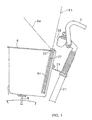
- Fig. 1 is a side view of a major part of the bicycle.
- a rear portion of the basket 7 is engaged with the head pipe 21 by a latch 29.
- the latch 29 has it one end connected to an upper portion of the head pipe 21, and its other end connected to a rear wall of the basket 7 by, for example, a bolt-nut combination.
- the panel 8 is supported by a pivot shaft 26 extending in the left-right direction on the rear side of the vehicle body with respect to the basket 7, and is provided turnably with the pivot shaft 26 as a center.
- the upper side of the basket 7 is opened by turning the panel 8 clockwise in the figure as indicated by 8a-8b from the condition of making contact with the brim of the basket 7. Further, the panel 8 is moved downwards, directly in the erected posture indicated by symbol 8b.
- the pivot shaft 26 of the panel 8 is guided by vertical guide holes 27 provided at left and right positions near the rear portion of the basket 7, and the panel 8 is stored in the basket 7 as indicated by symbol 8c.
- a main switch 28 of the motor-assisted bicycle 1 is provided in the vicinity of a central portion of the handle 4.
- Fig. 3 is a plan view showing a roughly right half of the panel and the basket
- Fig. 4 is a perspective view of a major part showing an engaging portion between the basket and the panel
- Fig. 5 is a perspective view of a major part of the basket showing the condition where the panel is stored
- Fig. 6 is a view from the upper side of the basket showing the condition where the panel is stored
- Fig. 7 is a perspective view of a major part in the vicinity of the brim of the basket.
- vertically elongate frame bodies 28 are attached to left and right side surfaces of the basket 7.
- the frame body 28 is assembled with a window 281 in the manner of overlapping with a slit 71 formed in each side portion of the basket 7, and the window 281 and the slit 71 constitute the guide hole 27.
- the slit 71 is opened at the brim of the basket 7 (See Fig. 7).
- the position of the frame body 28 is so set that the upper end of the window 281 is located to be extended to the upper side of the opened portion.
- the pivot shaft 26 is bosses 61 extended to the left and right outsides from the panel 8, and the bosses are projected to the outside through the guide holes 27, namely, the slits 71 and the windows 281.
- An end portion of the boss 261 is provided with a threaded hole, and a set screw 31 is screwed into the threaded hole.
- the condition where the panel 8 is erected from the position shown in Figs. 3 and 4 and the bosses 261 are moved along the guide holes 27 to the lowermost portions is shown in Figs. 5 and 6.
- the panel 8 is stored along the rear inside wall of the basket 7, so that the appearance is simple, and the vertical movements of the panel 8 in the basket 7 are smoothly performed along the guide holes 27.
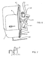
- Fig. 8 is a perspective sectional view showing a left half of a front portion of the bicycle according to the modified example
- Fig. 9 is a side sectional view of the same
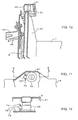
- Fig. 10 is a view from the lower side of a rear portion of the basket.
- Fig. 11 is a plan view of a front portion of the panel
- Fig. 12 is a sectional view taken along B-B of Fig. 11.
- the panel 8 is provided with a lock. While the panel 8 is used for charging the battery 10, it is so disposed as to cover an upper portion of the basket 7 and, therefore, functions as a lid for the basket 7. In this modified example, the panel 8 is integrally provided with the lock, whereby the function as the lid is more enriched, and antitheft function for the panel 8 itself is attained.
- a tubular lock device 32 projecting to the lower side of the panel 8 (in the roughly horizontal posture along the brim of the basket) is provided at a central portion of the front end of the panel 8.
- the panel 8 has a front wall 81 in the manner of covering the lock device 32.
- the basket 7 has a horizontal portion 72 opposed to the lower side of the lock device 32 when the panel is set in the roughly horizontal posture so as to cover the upper portion of the basket 7, and a vertical member 73 provided with a hole for engagement with a plunger 321 of the lock device 32 is erected on the horizontal member 72.
- a cable 40 for transmitting electric power generated which extends to the battery 10 is connected to the vicinity of the pivot shaft of the panel 8. As seen from Figs.
- a partition wall 33 disposed in parallel to the rear wall of the basket 7 is provided.
- the partition wall 33 may be provided with an engaging and stopping block 34 at an upper portion thereof.
- the engaging and stopping block 34 has a portion having the same function as the vertical member 73 of Fig. 11 which is engaged with the plunger 321 of the lock device 32 at a position where the panel 8 is stored in the basket 8. Therefore, also in the condition where the panel 8 is stored in the basket 7, the panel 8 is fixed to the basket 7 by the lock device 32.
- the partition wall 33 provides means for indicating the engaging and stopping block 34, and functions to partition the inside of the basket 7 into a luggage-storing space and a space for storing the panel 8, thereby enhancing a protective effect for the panel 8.
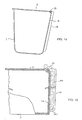
- a second modified example While a structure capable of storing the panel 8 in the basket 7 is adopted in the above example, the panel 8 is stored in a holding portion provided on the rear outside of the basket 7 in this second modified example.
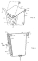
- Fig. 13 is a perspective view of the basket
- Fig. 14 is a side sectional view
- Fig. 15 is an enlarged sectional view.
- the panel 8 is hooked on hooks 35 provided at a rear upper portion of the basket, in the posture of being mounted roughly horizontally on the basket 7.
- the hooks 35 each have such a shape as to project upwards from the upper edge of the rear wall 74 of the basket 7 and be bent toward the rear portion of the vehicle body.
- the hooks 35 are provided at a plurality of positions (in this example, four positions) in the width direction of the basket 7, and the panel 8 is provided with engaging holes 82 engageable with the hooks 35, at the same intervals as the hooks 35.
- the hooks 35 are engaged with the engaging holes 82, with the panel 8 in a vertically erected posture.
- the panel 8 is tilted down to a horizontal posture to cover an upper portion of the basket 7.
- the engagement between the engaging holes 82 and the hooks 35 is released, and the panel 8 can be separated from the basket 7.
- a holding portion capable of accommodating the panel 8 separated from the basket 7 is provided on the outside of the basket 7.
- a pair of angle members 36 L-shaped in horizontal sectional shape are fitted in the state of being separated from each other in the width direction of the vehicle body, on the outside of the rear wall 74 of the basket 7, as a holding member for the panel 8.
- the angle member 36 has a receiving portion 361 at a lower portion thereof. Both left and right ends of the panel 8 separated from the basket 7 are guided by the angle members 36, and an end face of the panel 8 located on the rear side at the time of being fitted, namely, the end face on the side where the engaging holes 82 are provided is received by the receiving portions 361, and the panel 8 is held in the posture indicated by symbol 8d in Fig. 14.
- the basket 7 has a shape contracted to be smaller on the lower side. Therefore, when the panel 8 is formed in a storable shape conforming to the shape of the basket 7, the width of the panel 8 must be reduced on the side of the rear portion of the basket 7 as shown in Fig. 13. Therefore, when the panel 8 is set to cover the upper portion of the basket 7, gaps G are generated (See Fig. 13) .
- Fig. 16 is a perspective view of the basket 7 according to the third modified example, in which the same symbols as in Fig. 13 denote the same or equivalent portions.
- triangular auxiliary plates 37 capable of covering the gaps G are provided in the width direction of the panel 8.
- the auxiliary plates 37 are each connected to the panel 8 by a hinge 38.
- the auxiliary plates 37 can be folded, and laid on the panel 8, by utilizing pivot shafts of the hinges 38.
- the panel 8 can be enlarged by developing so as to eliminate the gaps at the time of covering the upper portion of the basket 7; on the other hand, at the time of being stored on the rear side of the basket 7, the panel 8 can be reduced in size by folding the auxiliary plates 3.
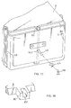
- Fig. 17 is a perspective view of a rear portion of the basket 7 according to a fourth modified example
- Fig. 18 is a perspective view of a cable connecting portion of the panel 8.
- a cable connecting portion 85 for connecting a cable 40 for transmitting the electric power generated by the panel 8 to the battery 10 is provided at a rear portion of the panel 8.
- the cable 40 is connected to an output terminal (not shown) of the panel 8 by the cable connecting portion 85.
- the cable 40 is led out to the rear side of the vehicle body through a through-hole 741 provided in the rear wall 74 of the basket 7, and is connected to the battery 10 through the above-mentioned harness 18.
- a diode 41 for inhibiting reverse flow of electric current is provided at an intermediate portion of the cable 40.
- the panel 8 is stored near the rear wall 74 of the basket 7, with the cable connecting portion 85 on the lower side (posture 8d in Fig. 17).
- the cable 40 is so treated as to extend upwards from the cable connecting portion 85 to reach the through-hole 741.
- the leading-out direction of the cable 40 is changed by 180° , between the situation where the panel 8 is mounted on the basket 7 in a roughly horizontal posture and the situation where the panel 8 is stored in a roughly vertical posture.
- the cable connecting portion 85 is provided with a groove 851 opened in two directions as shown in Fig. 18, so as thereby to cope with treatment of the cable 40.
- Fig. 19 is a side view of a bicycle comprising a basket (rear basket) mounted on a luggage carrier at a lower portion thereof, in which the same symbols as in Fig. 2 denote the same or equivalent portions.
- the rear basket 43 is fixed on the luggage carrier 42 located on the rear side of the seat 9, and the panel 8 is provided on the rear basket 43.
- the panel 8 is fitted turnably by a pivot shaft 26, in the same manner as in the case of fitting on the basket 7 located at a front portion of the vehicle body. It should be noted here, however, that the pivot shaft 26 is provided near the front wall of the rear basket 43.
- the pivot shaft 26 is guided vertically in guide holes 27 provided at side surfaces of the rear basket 43, whereby the panel 8 can be stored in the rear basket 43, which is a constitution applicable in common to the one shown in Fig. 1.
- the structure shown in Fig. 19 is not limitative; the structures for storing the panel 8 on the inside or outside of the rear basket 43 are the same as the structures for storing the panel 8 on the inside or outside of the front basket 7. Therefore, the constitutions described referring to Figs. 1 to 18 above can be applied to the rear basket 43 and the panel 8 mounted thereon in a roughly horizontal posture. In the application, it is natural that modifications can be appropriately made by known means according to the shape and size of the rear basket 43.
- the present invention is not limited to the above embodiments; the present invention can be widely applied generally to motor-assisted vehicles in which tread force is assisted by power of an electric motor, and can be applied to motor-driven vehicles such as a motor-driven wheel chair for running by power of an electric motor. Further, the present invention can be used for engine vehicles, for example, those which comprise a solar cell panel for charging a starting battery.
- the panel can not only be provided on the basket provided at a front portion or a rear portion of the vehicle body but can also be provided on each of the baskets provided at a front portion and a rear portion of the vehicle body.
- a solar cell panel 8 is supported on a front basket 7 in a horizontal posture, to receive light. In the cases of night or raining when sunlight is not received, the panel 8 is stored in the basket 7. Particularly, the panel 8 is supported by a pivot shaft 26 near a rear wall of the basket 7 so that it can be swiveled relative to the basket 7. Side surfaces of the basket 7 are provided with guide holes 7 for guiding the panel 8 through the pivot shaft 26 at the time of storing. The pivot shaft 26 is guided by the guide holes 27, and the panel 8 is stored in the basket 7 with the pivot shaft 26 on the lower side.
Landscapes
- Engineering & Computer Science (AREA)
- Mechanical Engineering (AREA)
- Chemical & Material Sciences (AREA)
- Combustion & Propulsion (AREA)
- Transportation (AREA)
- Power Engineering (AREA)
- Sustainable Development (AREA)
- Sustainable Energy (AREA)
- Life Sciences & Earth Sciences (AREA)
- Photovoltaic Devices (AREA)
- Packaging Of Machine Parts And Wound Products (AREA)
- Fittings On The Vehicle Exterior For Carrying Loads, And Devices For Holding Or Mounting Articles (AREA)
- Automatic Cycles, And Cycles In General (AREA)
Applications Claiming Priority (2)
| Application Number | Priority Date | Filing Date | Title |
|---|---|---|---|
| JP2001291299 | 2001-09-25 | ||
| JP2001291299A JP2003095183A (ja) | 2001-09-25 | 2001-09-25 | 太陽電池付き車両 |
Publications (3)
| Publication Number | Publication Date |
|---|---|
| EP1295784A2 true EP1295784A2 (de) | 2003-03-26 |
| EP1295784A3 EP1295784A3 (de) | 2003-10-01 |
| EP1295784B1 EP1295784B1 (de) | 2011-05-11 |
Family
ID=19113470
Family Applications (1)
| Application Number | Title | Priority Date | Filing Date |
|---|---|---|---|
| EP02019916A Expired - Lifetime EP1295784B1 (de) | 2001-09-25 | 2002-09-04 | Fahrzeug mit Solarzellen |
Country Status (6)
| Country | Link |
|---|---|
| EP (1) | EP1295784B1 (de) |
| JP (1) | JP2003095183A (de) |
| CN (1) | CN1281432C (de) |
| AT (1) | ATE508932T1 (de) |
| ES (1) | ES2363328T3 (de) |
| TW (1) | TW590948B (de) |
Cited By (7)
| Publication number | Priority date | Publication date | Assignee | Title |
|---|---|---|---|---|
| ITBO20110144A1 (it) * | 2011-03-23 | 2012-09-24 | Simon Plast Ind S R L | Veicolo azionato a passo |
| CN106828696A (zh) * | 2017-01-09 | 2017-06-13 | 上海共佰克智能科技有限公司 | 一种车把手以及自行车 |
| CN109866861A (zh) * | 2019-02-14 | 2019-06-11 | 张艺涵 | 便携式充电单车 |
| CN110803044A (zh) * | 2019-11-06 | 2020-02-18 | 徐州华创电子有限公司 | 一种电动车充电装置 |
| US20200172195A1 (en) * | 2017-08-07 | 2020-06-04 | Hangzhou Qingqi Science And Technology Co., Ltd. | Shared bicycle that can be charged conveniently |
| DE202020107472U1 (de) | 2020-12-22 | 2022-02-17 | MPR GmbH & Co. KG | System zur Anbringung eines Zubehörteils an einem Fahrrad |
| DE102022207533A1 (de) | 2022-07-22 | 2023-07-06 | Zf Friedrichshafen Ag | System zur Versorgung eines elektrischen Zweirads mit elektrischer Energie |
Families Citing this family (5)
| Publication number | Priority date | Publication date | Assignee | Title |
|---|---|---|---|---|
| US20100264183A1 (en) | 2009-04-15 | 2010-10-21 | Kaczowski Michael J | Motorcycle saddlebag |
| CN102420441A (zh) * | 2010-09-28 | 2012-04-18 | 吴镇煜 | 用于电动车蓄电池的太阳能充电装置 |
| JP5277376B1 (ja) * | 2012-05-16 | 2013-08-28 | 絵里香 田村 | 幅広蓋付施錠防犯強化自転車用収容ボックス |
| CN108551304A (zh) * | 2018-04-24 | 2018-09-18 | 佛山市所能网络有限公司 | 一种防遮挡的太阳能电池板 |
| CN111086578B (zh) * | 2019-12-23 | 2021-11-19 | 绍兴悦通新能源科技有限公司 | 一种共享单车上的太阳能吊篮 |
Citations (1)
| Publication number | Priority date | Publication date | Assignee | Title |
|---|---|---|---|---|
| JP2000247287A (ja) | 1999-02-28 | 2000-09-12 | Yoshitaka Hashimoto | 自転車用外部環境検知制御補助動力システム |
Family Cites Families (2)
| Publication number | Priority date | Publication date | Assignee | Title |
|---|---|---|---|---|
| JP3008205B2 (ja) * | 1990-04-17 | 2000-02-14 | 株式会社東京アールアンドデー | ソーラーセル併用型の電動スクーター |
| JPH08111905A (ja) * | 1994-10-07 | 1996-04-30 | Sanyo Electric Co Ltd | 電気自動車 |
-
2001
- 2001-09-25 JP JP2001291299A patent/JP2003095183A/ja active Pending
-
2002
- 2002-09-04 EP EP02019916A patent/EP1295784B1/de not_active Expired - Lifetime
- 2002-09-04 AT AT02019916T patent/ATE508932T1/de not_active IP Right Cessation
- 2002-09-04 ES ES02019916T patent/ES2363328T3/es not_active Expired - Lifetime
- 2002-09-09 TW TW091120425A patent/TW590948B/zh not_active IP Right Cessation
- 2002-09-10 CN CNB021416699A patent/CN1281432C/zh not_active Expired - Fee Related
Patent Citations (1)
| Publication number | Priority date | Publication date | Assignee | Title |
|---|---|---|---|---|
| JP2000247287A (ja) | 1999-02-28 | 2000-09-12 | Yoshitaka Hashimoto | 自転車用外部環境検知制御補助動力システム |
Cited By (10)
| Publication number | Priority date | Publication date | Assignee | Title |
|---|---|---|---|---|
| ITBO20110144A1 (it) * | 2011-03-23 | 2012-09-24 | Simon Plast Ind S R L | Veicolo azionato a passo |
| CN106828696A (zh) * | 2017-01-09 | 2017-06-13 | 上海共佰克智能科技有限公司 | 一种车把手以及自行车 |
| US20200172195A1 (en) * | 2017-08-07 | 2020-06-04 | Hangzhou Qingqi Science And Technology Co., Ltd. | Shared bicycle that can be charged conveniently |
| EP3650328A4 (de) * | 2017-08-07 | 2020-06-10 | Hangzhou Qingqi Science And Technology Co., Ltd. | Gemeinsames fahrrad mit praktischem aufladen |
| US11820455B2 (en) * | 2017-08-07 | 2023-11-21 | Hangzhou Qingqi Science And Technology Co., Ltd. | Shared bicycle that can be charged conveniently |
| CN109866861A (zh) * | 2019-02-14 | 2019-06-11 | 张艺涵 | 便携式充电单车 |
| CN109866861B (zh) * | 2019-02-14 | 2023-12-26 | 张艺涵 | 便携式充电单车 |
| CN110803044A (zh) * | 2019-11-06 | 2020-02-18 | 徐州华创电子有限公司 | 一种电动车充电装置 |
| DE202020107472U1 (de) | 2020-12-22 | 2022-02-17 | MPR GmbH & Co. KG | System zur Anbringung eines Zubehörteils an einem Fahrrad |
| DE102022207533A1 (de) | 2022-07-22 | 2023-07-06 | Zf Friedrichshafen Ag | System zur Versorgung eines elektrischen Zweirads mit elektrischer Energie |
Also Published As
| Publication number | Publication date |
|---|---|
| CN1410292A (zh) | 2003-04-16 |
| ES2363328T3 (es) | 2011-08-01 |
| TW590948B (en) | 2004-06-11 |
| ATE508932T1 (de) | 2011-05-15 |
| EP1295784B1 (de) | 2011-05-11 |
| JP2003095183A (ja) | 2003-04-03 |
| CN1281432C (zh) | 2006-10-25 |
| EP1295784A3 (de) | 2003-10-01 |
Similar Documents
| Publication | Publication Date | Title |
|---|---|---|
| EP2978659B1 (de) | Motorroller | |
| EP1295784B1 (de) | Fahrzeug mit Solarzellen | |
| EP0844169B1 (de) | Kleinfahrzeug | |
| EP2574531B1 (de) | Elektrisches Fahrzeug | |
| US10870460B2 (en) | Compact folding electric bicycle | |
| US5633095A (en) | Battery holding structure | |
| US6010173A (en) | Sunshield for motorcycles | |
| US5789898A (en) | Battery holding device for vehicle | |
| EP0648633B1 (de) | Elektrofahrzeug mit Abdeckung und Behälter zur Aufnahme der Batterie | |
| US9070925B2 (en) | Battery charger and battery charger attaching structure | |
| EP2738080B1 (de) | Anordnungsstruktur für elektrisches bauelement eines elektrofahrzeuges | |
| JP3682734B2 (ja) | 電動自転車 | |
| US8919483B2 (en) | Ridden vehicle with integrated fuel tank | |
| WO2011033967A1 (ja) | 電動二輪車 | |
| EP0729878B1 (de) | Befestigungsvorrichtung für Fahrradsattel | |
| CN109153422B (zh) | 用于双轮车的车身 | |
| JPH08207874A (ja) | 電動自転車 | |
| WO2008129589A2 (en) | Variable-geometry system for capturing solar and photovoltaic energy that can be applied on electrically driven vehicles | |
| JP2014043167A (ja) | 鞍乗り型車両の携帯端末収納構造 | |
| JP3976382B2 (ja) | カバー付自転車 | |
| JP3815869B2 (ja) | 電動自転車 | |
| JP2001097275A (ja) | 電動補助自転車のバッテリ取付構造 | |
| CN219904606U (zh) | 车辆的电池收纳装置 | |
| US11117632B2 (en) | Rider's seat for a two-wheeled vehicle | |
| CN103534165A (zh) | 两轮车 |
Legal Events
| Date | Code | Title | Description |
|---|---|---|---|
| PUAI | Public reference made under article 153(3) epc to a published international application that has entered the european phase |
Free format text: ORIGINAL CODE: 0009012 |
|
| AK | Designated contracting states |
Kind code of ref document: A2 Designated state(s): AT BE BG CH CY CZ DE DK EE ES FI FR GB GR IE IT LI LU MC NL PT SE SK TR |
|
| AX | Request for extension of the european patent |
Extension state: AL LT LV MK RO SI |
|
| PUAL | Search report despatched |
Free format text: ORIGINAL CODE: 0009013 |
|
| AK | Designated contracting states |
Kind code of ref document: A3 Designated state(s): AT BE BG CH CY CZ DE DK EE ES FI FR GB GR IE IT LI LU MC NL PT SE SK TR |
|
| AX | Request for extension of the european patent |
Extension state: AL LT LV MK RO SI |
|
| RIC1 | Information provided on ipc code assigned before grant |
Ipc: 7B 62J 9/00 A Ipc: 7B 62M 23/02 B Ipc: 7B 62K 19/46 B Ipc: 7B 60L 8/00 B |
|
| 17P | Request for examination filed |
Effective date: 20031125 |
|
| AKX | Designation fees paid |
Designated state(s): AT BE BG CH CY CZ DE DK EE ES FI FR GB GR IE IT LI LU MC NL PT SE SK TR |
|
| 17Q | First examination report despatched |
Effective date: 20070111 |
|
| GRAP | Despatch of communication of intention to grant a patent |
Free format text: ORIGINAL CODE: EPIDOSNIGR1 |
|
| GRAS | Grant fee paid |
Free format text: ORIGINAL CODE: EPIDOSNIGR3 |
|
| GRAA | (expected) grant |
Free format text: ORIGINAL CODE: 0009210 |
|
| RIN1 | Information on inventor provided before grant (corrected) |
Inventor name: CHO, TOSHIYUKIC/O KABUSHIKI KAISHA HONDA GIJUTSU K Inventor name: NAKAGOMI, YOSHIOC/O KABUSHIKI KAISHA HONDA GIJUTSU |
|
| AK | Designated contracting states |
Kind code of ref document: B1 Designated state(s): AT BE BG CH CY CZ DE DK EE ES FI FR GB GR IE IT LI LU MC NL PT SE SK TR |
|
| REG | Reference to a national code |
Ref country code: GB Ref legal event code: FG4D |
|
| REG | Reference to a national code |
Ref country code: CH Ref legal event code: EP Ref country code: CH Ref legal event code: NV Representative=s name: BOHEST AG |
|
| REG | Reference to a national code |
Ref country code: IE Ref legal event code: FG4D |
|
| REG | Reference to a national code |
Ref country code: DE Ref legal event code: R096 Ref document number: 60239982 Country of ref document: DE Effective date: 20110622 |
|
| REG | Reference to a national code |
Ref country code: NL Ref legal event code: T3 |
|
| REG | Reference to a national code |
Ref country code: ES Ref legal event code: FG2A Ref document number: 2363328 Country of ref document: ES Kind code of ref document: T3 Effective date: 20110801 |
|
| PG25 | Lapsed in a contracting state [announced via postgrant information from national office to epo] |
Ref country code: PT Free format text: LAPSE BECAUSE OF FAILURE TO SUBMIT A TRANSLATION OF THE DESCRIPTION OR TO PAY THE FEE WITHIN THE PRESCRIBED TIME-LIMIT Effective date: 20110912 Ref country code: SE Free format text: LAPSE BECAUSE OF FAILURE TO SUBMIT A TRANSLATION OF THE DESCRIPTION OR TO PAY THE FEE WITHIN THE PRESCRIBED TIME-LIMIT Effective date: 20110511 |
|
| PGFP | Annual fee paid to national office [announced via postgrant information from national office to epo] |
Ref country code: CH Payment date: 20110913 Year of fee payment: 10 |
|
| PG25 | Lapsed in a contracting state [announced via postgrant information from national office to epo] |
Ref country code: FI Free format text: LAPSE BECAUSE OF FAILURE TO SUBMIT A TRANSLATION OF THE DESCRIPTION OR TO PAY THE FEE WITHIN THE PRESCRIBED TIME-LIMIT Effective date: 20110511 Ref country code: BE Free format text: LAPSE BECAUSE OF FAILURE TO SUBMIT A TRANSLATION OF THE DESCRIPTION OR TO PAY THE FEE WITHIN THE PRESCRIBED TIME-LIMIT Effective date: 20110511 Ref country code: AT Free format text: LAPSE BECAUSE OF FAILURE TO SUBMIT A TRANSLATION OF THE DESCRIPTION OR TO PAY THE FEE WITHIN THE PRESCRIBED TIME-LIMIT Effective date: 20110511 Ref country code: CY Free format text: LAPSE BECAUSE OF FAILURE TO SUBMIT A TRANSLATION OF THE DESCRIPTION OR TO PAY THE FEE WITHIN THE PRESCRIBED TIME-LIMIT Effective date: 20110511 Ref country code: GR Free format text: LAPSE BECAUSE OF FAILURE TO SUBMIT A TRANSLATION OF THE DESCRIPTION OR TO PAY THE FEE WITHIN THE PRESCRIBED TIME-LIMIT Effective date: 20110812 |
|
| PG25 | Lapsed in a contracting state [announced via postgrant information from national office to epo] |
Ref country code: EE Free format text: LAPSE BECAUSE OF FAILURE TO SUBMIT A TRANSLATION OF THE DESCRIPTION OR TO PAY THE FEE WITHIN THE PRESCRIBED TIME-LIMIT Effective date: 20110511 Ref country code: CZ Free format text: LAPSE BECAUSE OF FAILURE TO SUBMIT A TRANSLATION OF THE DESCRIPTION OR TO PAY THE FEE WITHIN THE PRESCRIBED TIME-LIMIT Effective date: 20110511 |
|
| PG25 | Lapsed in a contracting state [announced via postgrant information from national office to epo] |
Ref country code: SK Free format text: LAPSE BECAUSE OF FAILURE TO SUBMIT A TRANSLATION OF THE DESCRIPTION OR TO PAY THE FEE WITHIN THE PRESCRIBED TIME-LIMIT Effective date: 20110511 Ref country code: DK Free format text: LAPSE BECAUSE OF FAILURE TO SUBMIT A TRANSLATION OF THE DESCRIPTION OR TO PAY THE FEE WITHIN THE PRESCRIBED TIME-LIMIT Effective date: 20110511 |
|
| PLBE | No opposition filed within time limit |
Free format text: ORIGINAL CODE: 0009261 |
|
| STAA | Information on the status of an ep patent application or granted ep patent |
Free format text: STATUS: NO OPPOSITION FILED WITHIN TIME LIMIT |
|
| 26N | No opposition filed |
Effective date: 20120214 |
|
| PG25 | Lapsed in a contracting state [announced via postgrant information from national office to epo] |
Ref country code: MC Free format text: LAPSE BECAUSE OF NON-PAYMENT OF DUE FEES Effective date: 20110930 |
|
| REG | Reference to a national code |
Ref country code: GB Ref legal event code: 746 Effective date: 20120521 |
|
| REG | Reference to a national code |
Ref country code: DE Ref legal event code: R097 Ref document number: 60239982 Country of ref document: DE Effective date: 20120214 |
|
| REG | Reference to a national code |
Ref country code: IE Ref legal event code: MM4A |
|
| PG25 | Lapsed in a contracting state [announced via postgrant information from national office to epo] |
Ref country code: IE Free format text: LAPSE BECAUSE OF NON-PAYMENT OF DUE FEES Effective date: 20110904 |
|
| REG | Reference to a national code |
Ref country code: DE Ref legal event code: R084 Ref document number: 60239982 Country of ref document: DE Effective date: 20120523 |
|
| PGFP | Annual fee paid to national office [announced via postgrant information from national office to epo] |
Ref country code: GB Payment date: 20120829 Year of fee payment: 11 |
|
| PGFP | Annual fee paid to national office [announced via postgrant information from national office to epo] |
Ref country code: DE Payment date: 20120829 Year of fee payment: 11 Ref country code: IT Payment date: 20120915 Year of fee payment: 11 Ref country code: FR Payment date: 20120926 Year of fee payment: 11 |
|
| PGFP | Annual fee paid to national office [announced via postgrant information from national office to epo] |
Ref country code: NL Payment date: 20120908 Year of fee payment: 11 |
|
| PGFP | Annual fee paid to national office [announced via postgrant information from national office to epo] |
Ref country code: ES Payment date: 20121004 Year of fee payment: 11 |
|
| PG25 | Lapsed in a contracting state [announced via postgrant information from national office to epo] |
Ref country code: LU Free format text: LAPSE BECAUSE OF NON-PAYMENT OF DUE FEES Effective date: 20110904 |
|
| PG25 | Lapsed in a contracting state [announced via postgrant information from national office to epo] |
Ref country code: BG Free format text: LAPSE BECAUSE OF FAILURE TO SUBMIT A TRANSLATION OF THE DESCRIPTION OR TO PAY THE FEE WITHIN THE PRESCRIBED TIME-LIMIT Effective date: 20110811 |
|
| PG25 | Lapsed in a contracting state [announced via postgrant information from national office to epo] |
Ref country code: TR Free format text: LAPSE BECAUSE OF FAILURE TO SUBMIT A TRANSLATION OF THE DESCRIPTION OR TO PAY THE FEE WITHIN THE PRESCRIBED TIME-LIMIT Effective date: 20110511 |
|
| REG | Reference to a national code |
Ref country code: NL Ref legal event code: V1 Effective date: 20140401 |
|
| REG | Reference to a national code |
Ref country code: CH Ref legal event code: PL |
|
| GBPC | Gb: european patent ceased through non-payment of renewal fee |
Effective date: 20130904 |
|
| REG | Reference to a national code |
Ref country code: FR Ref legal event code: ST Effective date: 20140530 |
|
| REG | Reference to a national code |
Ref country code: DE Ref legal event code: R119 Ref document number: 60239982 Country of ref document: DE Effective date: 20140401 |
|
| PG25 | Lapsed in a contracting state [announced via postgrant information from national office to epo] |
Ref country code: CH Free format text: LAPSE BECAUSE OF NON-PAYMENT OF DUE FEES Effective date: 20130930 Ref country code: GB Free format text: LAPSE BECAUSE OF NON-PAYMENT OF DUE FEES Effective date: 20130904 Ref country code: LI Free format text: LAPSE BECAUSE OF NON-PAYMENT OF DUE FEES Effective date: 20130930 |
|
| PG25 | Lapsed in a contracting state [announced via postgrant information from national office to epo] |
Ref country code: FR Free format text: LAPSE BECAUSE OF NON-PAYMENT OF DUE FEES Effective date: 20130930 Ref country code: DE Free format text: LAPSE BECAUSE OF NON-PAYMENT OF DUE FEES Effective date: 20140401 Ref country code: IT Free format text: LAPSE BECAUSE OF NON-PAYMENT OF DUE FEES Effective date: 20130904 Ref country code: NL Free format text: LAPSE BECAUSE OF NON-PAYMENT OF DUE FEES Effective date: 20140401 |
|
| REG | Reference to a national code |
Ref country code: ES Ref legal event code: FD2A Effective date: 20150506 |
|
| PG25 | Lapsed in a contracting state [announced via postgrant information from national office to epo] |
Ref country code: ES Free format text: LAPSE BECAUSE OF NON-PAYMENT OF DUE FEES Effective date: 20130905 |