EP1295973A1 - Appareil et procédé pour le transport de matériaux textiles en bande - Google Patents
Appareil et procédé pour le transport de matériaux textiles en bande Download PDFInfo
- Publication number
- EP1295973A1 EP1295973A1 EP01122930A EP01122930A EP1295973A1 EP 1295973 A1 EP1295973 A1 EP 1295973A1 EP 01122930 A EP01122930 A EP 01122930A EP 01122930 A EP01122930 A EP 01122930A EP 1295973 A1 EP1295973 A1 EP 1295973A1
- Authority
- EP
- European Patent Office
- Prior art keywords
- conveyor belt
- louvers
- installation according
- textile fabric
- air
- Prior art date
- Legal status (The legal status is an assumption and is not a legal conclusion. Google has not performed a legal analysis and makes no representation as to the accuracy of the status listed.)
- Granted
Links
- 239000004753 textile Substances 0.000 title claims abstract description 47
- 238000000034 method Methods 0.000 title claims abstract description 6
- 238000004519 manufacturing process Methods 0.000 claims abstract description 6
- 239000004744 fabric Substances 0.000 claims description 40
- 238000009960 carding Methods 0.000 claims description 12
- 239000000835 fiber Substances 0.000 claims description 3
- 238000009434 installation Methods 0.000 claims 15
- 230000032258 transport Effects 0.000 abstract 1
- 239000000463 material Substances 0.000 description 3
- 101100390736 Danio rerio fign gene Proteins 0.000 description 2
- 101100390738 Mus musculus Fign gene Proteins 0.000 description 2
- 239000000853 adhesive Substances 0.000 description 1
- 230000001070 adhesive effect Effects 0.000 description 1
- 238000005265 energy consumption Methods 0.000 description 1
- 239000002657 fibrous material Substances 0.000 description 1
- 239000000203 mixture Substances 0.000 description 1
Images


Classifications
-
- D—TEXTILES; PAPER
- D01—NATURAL OR MAN-MADE THREADS OR FIBRES; SPINNING
- D01G—PRELIMINARY TREATMENT OF FIBRES, e.g. FOR SPINNING
- D01G25/00—Lap-forming devices not integral with machines specified above
Definitions
- the invention relates to a system and a method for transporting textile Fabrics according to the preamble of claim 1 and claim 20, as well as a plant and a method for producing nonwoven webs according to the preamble of claim 16 or 22nd
- the invention is based on the object, a system and a method for Transporting textile fabrics or for producing nonwoven webs to create the transport of textile fabrics even at high transport speeds without permanent suction by suction devices allows.
- Die Invention provides advantageously that on the textile fabric opposite side of the conveyor belt several transverse to the conveyor belt extending air deflectors are arranged, that of the conveyor belt entrain entrained air on the side facing away from the textile fabric side.
- the invention advantageously allows the transport of textile Fabrics with a high transport speed of over 100 m / min without one permanent suction of conveyor belts through the use of suction devices on the bottom of it.
- the one for transport with high transport speeds required intake air flow is solely by the deflection of the achieved at the bottom of the conveyor belt entrained air. This results a proportional relationship between the conveyor belt speed and the adhesive force of the textile fabric on the conveyor belt. Because the plant no suction required, eliminating the need for a regulation of the suction. In addition, the power consumption of the suction, eliminates so that not only the investment costs but also the operating costs are reduced can be.
- the conveyor belt facing edge of the louvers runs along low, preferably adjustable distance from the conveyor belt.
- the low one Distance of the louvers from the conveyor belt ensures that the By far the greater part of the transport belt carried on the underside Air can be diverted to the desired air flow through the air To achieve textile fabrics and the conveyor belt. Because of the distance is adjustable, there is the possibility to adjust the suction power. Preferably, however, a distance between 0.1 and 10 mm is set.
- the louvers are preferably at a distance from the conveyor belt stationary supporting structure fixed fixed or alternatively parallel and in Slidably mounted longitudinally to the conveyor belt. Also the parallel shift allows the louvers in the longitudinal direction of the conveyor belt an individual adjustment of the air flow to specific requirements in certain Track sections of the conveyor belt. Preferably, the louvers have in the transport direction an equal distance from each other.
- the louvers are one parallel to the conveyor belt and transverse to the direction of transport axis pivotable. In this way, the distance of the louvers from the Conveyor belt in a simple manner and quickly adjustable.
- the louvers only in Edge region of the conveyor belt are arranged.
- the textile Sheet material in particular by its sucked edge areas on the Held conveyor belt.
- air guiding devices over the entire working width of the conveyor belt or only in the edge area are provided in an alternating arrangement. It can also several Air guiding devices of the same type can be arranged one behind the other.
- the louvers can at an angle of about 5 to 90 ° relative to the Movement level of the conveyor belt run.
- the louvers have according to a preferred embodiment in Cross section of an aerodynamic wing profile.
- the aerodynamic wing shape supports the deflection of the air entrained in the conveyor belt and increases thereby the suction power and thus the adhesion of the textile fabric the conveyor belt.
- louvers arrowhead in plan view run, with the arrowhead in the middle of the conveyor belt arranged a can.
- Such a design of the louvers allows an additional Generate transverse component of the air flow.
- the arrow-shaped arrangement of the louvers in plan view also be provided only in the border area.
- rotating parts can be used to prevent the trailing air from rotating Part Heilabstreif Raniedtreif Ranieden arranged, for example in the form of a doctor blade be.
- Such Heilabstreifshire are, for example, to the guide rollers of the Conveyor belt arranged to avoid that from the guide rollers entrained trailing air from below in the direction of the conveyor belt generated.
- louvers may be adjustable in groups together.
- the angle and the distance of the louvers to the conveyor belt and / or the mutual distance of the louvers in the transport direction can depend on the transport speed and / or basis weight and / or the fiber specification of the textile fabric automatically be adjustable.
- a suction device In the spaces between the louvers may be in the range of Transfer points at which the textile fabric is transferred to the conveyor belt is, using a suction device, a suction air flow for a short Time interval for starting assistance to be generated.
- a suction device can support the adhesion of the textile fabric during start-up operation and will be on reaching the transport speed or already before, for example, from a conveyor belt speed of 80 m / min, switched off.
- the invention further relates to a system for producing nonwoven webs with at least one card or card and with at least one evacuated permeable Conveyor belt for the transport of the card and / or carding produced Nonwoven web, this system with a transport system with the features of claims 1 to 15 is provided.
- the conveyor belt can be a mechanically produced nonwoven web or an aerodynamic transport generated nonwoven web.
- the plant for producing nonwoven webs can also have several nonwoven webs one above the other transferred to a single conveyor belt.
- the nonwoven webs can be generated by different cards or come from a Doppelab Strukturkrempel, each with a nonwoven web of a Conveyor belt is adopted.
- An upper nonwoven web is then from a upper conveyor belt on a lower nonwoven web on a lower conveyor belt passed and due to the air flow through the conveyor belt on the underlying Nonwoven web fixed.
- the arrangement of two conveyor belts one above the other has the further advantage that the air flowing through the upper conveyor belt, which is also through the lower Conveyor belt is passed, is highly uniformed, whereby the risk of air turbulence is greatly reduced.
- the inventive method for transporting textile fabrics with a permeable and evacuated conveyor belt by passing a textile Sheet on the moving conveyor belt provides that increased Contact pressure on the textile fabric by deflecting the on the underside of the conveyor belt entrained drag air is generated.
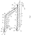
- Fig. 1 shows a plant for transporting textile fabrics with a Conveyor belt 4 for the transport of a textile fabric, by a Textile machine on the conveyor belt 4 passed to a transfer point 5 has been.
- the textile fabric can, for example, a random web, a Fabric, a film, pulp (chopped fiber material) or a nonwoven web 1, as supplied by a card or card 2, or a combination or mixture of the aforementioned materials.
- Fig. 1 shows take-off rollers 35,36 of a carding machine 2, which is a textile fabric in the form of a nonwoven web 1 mechanically on the conveyor belt 4 at the transfer point 5 put down.
- a take-off roll may also be used a nonwoven web 1 transferred to the conveyor belt 4.
- the conveyor belt 4 can also circulates endlessly and is permeable to air so that it flows from the Top of the conveyor belt 4 can allow to its bottom.
- Below the Conveyor belt are a plurality of louvers 6 by means of brackets. 8 attached to a parallel to the conveyor belt 4 extending support structure 10.
- the louvers 6 can with the help of the brackets 8 along the support structure 10, e.g.
- the Air guiding devices 6 a same mutual distance, however, exists also the possibility to set different distances.
- the louvers 6 are pivotally mounted and in different angular positions fixable.
- the pivot joint 14 is arranged on the holder 8. Relative to the plane of movement of the conveyor belt 4 are, for example, angle of attack ⁇ of the louvers 6 between 5 and 90 °, preferably between 10 and 70 °, adjustable.
- angles refer to the underside of the wing-like profile of Air guiding devices 6 in Fig. 1 in relation to the transport plane or to the parallel to the transport plane extending support structure 10th
- the louvers 6 may consist of straight sheets or concave or have convex curvatures.
- wing shape leads to an increase in the air velocity in the area between the louvers 6.
- the wing shape be designed so that the curvature of the wing contour is towards the support structure 10 is progressively reinforced.
- the distance of the support structure 10 to the conveyor belt can also be variably adjustable.
- the adjustable distance of the conveyor belt facing edge 9 of the louvers 6 is set so that the edge 9 of the louvers the Conveyor belt not touched. Depending on the material of the textile fabric can also a greater distance may be required.
- the louvers 6 steer those of the conveyor belt 4, on its underside entrained air and thereby generate an air flow through the textile Sheet and the conveyor belt 4 therethrough, whereby the adhesion of the textile fabric or the nonwoven web 1 on the conveyor belt 4 in high Dimensions is increased.
- Modern high-speed textile machines allow production speeds of over 200 m / min, even Production speeds of over 500 m / min are sought.
- the described Plant for transporting textile fabrics is for such high transport speeds, since the adhesion of the nonwoven web 1 with increasing Speed is automatically increased, causing a disruption of the Uniformity of a delicate textile fabric due to air turbulence can be excluded.
- one of the louvers 6 is with the conveyor belt 4 facing edge 9 on the transfer point 5 opposite Bottom of the conveyor belt 4.
- the edge 9 below the Axle of the doffer roll 36 run.
- For the start-up operation may additionally include a suction device 34 for the area be provided before or behind (Fig. 1) of the transfer point 5, the short while of the startup mode and when reaching a higher conveyor belt speed for example, via a flap 38 and stopping a Fan can be switched off again.
- the suction device 34 when reaching a conveyor belt speed of at least 80 m / min are switched off.
- the support structure 10 may be with devices not shown in the drawings Be provided with the help of the louvers 6 groups in terms of Angle and distance to the conveyor belt and / or the position of the louvers 6 are adjustable relative to the transfer point 5.
- angle and distance to the conveyor belt under consideration the transport speed and / or the basis weight of the textile fabric 1 and / or the fiber specification of the textile fabric 1 automatically be set.
- an air deflector 22 is arranged, the of the air conveyor 4 entrained air deflected in front of the deflection roller 20. additionally can at the guide roller 20 a Heilabstreif adopted 28 in the form of a doctor blade be provided, which strips the entrained by the guide roller 20 air.
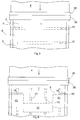
- Fig. 2 shows a plant for transporting textile fabrics 1, in the two nonwoven webs 1a, 1b are brought together on a lower conveyor belt 4.
- the nonwoven webs 1a, 1b can be fed from different carding machines or derive from a double buyer
- Both the upper conveyor belt 4a and the lower conveyor belt 4b are endlessly circulating and with those already described in connection with FIG Provided louvers 6.
- a roller 40 is arranged, for example consist of a smooth roll, a disk roll or a screen roll can and the nonwoven web 1a passes to the lower conveyor belt 4b.
- the louvers generate a high volume of air flow through the nonwoven web and the conveyor belt 4.
- FIG. 3 shows a plan view of the exemplary embodiment according to FIG. 1.
- Fig. 4 shows another embodiment of the louvers in which the Three-lane air ducts are with in edge regions 18 of the conveyor belt 4th arranged portions 6'a, 6'b and a central portion 6'c, the opposite the recessed in the edge region portions 6'a, 6'b is set back.
- the middle spoiler 6c ' also another angle and a have another distance to the conveyor belt 4.
- Fig. 5 shows another embodiment of the louvers 6 ", which is about the entire working width of the conveyor belt 4 extend.
- the in Figs. 4 to 6 illustrated arrow-shaped louvers 6 ', 6 ", 6"' allow an additional Cross-component of the air flow, which is either only in one edge area ( Figures 4 and 6) or over the entire working width is effective.
- Fig. 6 shows a side view of the embodiment of Fig. 5.
- the louvers 6 "are arranged in a puck-like manner one behind the other.
- FIGS. 5 and 6 is not an angle of attack of the louvers 6 "adjustable to the conveyor belt 4, but only the distance to the conveyor belt.
- Fig. 7 shows a further embodiment of the spoilers 6 "', the only are provided in an edge region 18 of the conveyor belt 4.
- Fig. 8 shows an embodiment of FIG. 7, wherein the louvers 6 'have a curvature opposite that of FIG. 7.
Landscapes
- Engineering & Computer Science (AREA)
- Textile Engineering (AREA)
- Preliminary Treatment Of Fibers (AREA)
Priority Applications (3)
| Application Number | Priority Date | Filing Date | Title |
|---|---|---|---|
| EP01122930A EP1295973B1 (fr) | 2001-09-25 | 2001-09-25 | Appareil et procédé pour le transport de matériaux textiles en bande |
| DE50108324T DE50108324D1 (de) | 2001-09-25 | 2001-09-25 | Anlage und Verfahren zum Transportieren von textilen Flächengebilden |
| US10/253,876 US6729465B2 (en) | 2001-09-25 | 2002-09-25 | Plant and a method for transporting textile fabrics |
Applications Claiming Priority (1)
| Application Number | Priority Date | Filing Date | Title |
|---|---|---|---|
| EP01122930A EP1295973B1 (fr) | 2001-09-25 | 2001-09-25 | Appareil et procédé pour le transport de matériaux textiles en bande |
Publications (2)
| Publication Number | Publication Date |
|---|---|
| EP1295973A1 true EP1295973A1 (fr) | 2003-03-26 |
| EP1295973B1 EP1295973B1 (fr) | 2005-12-07 |
Family
ID=8178718
Family Applications (1)
| Application Number | Title | Priority Date | Filing Date |
|---|---|---|---|
| EP01122930A Expired - Lifetime EP1295973B1 (fr) | 2001-09-25 | 2001-09-25 | Appareil et procédé pour le transport de matériaux textiles en bande |
Country Status (3)
| Country | Link |
|---|---|
| US (1) | US6729465B2 (fr) |
| EP (1) | EP1295973B1 (fr) |
| DE (1) | DE50108324D1 (fr) |
Cited By (2)
| Publication number | Priority date | Publication date | Assignee | Title |
|---|---|---|---|---|
| EP1672110A1 (fr) | 2004-12-16 | 2006-06-21 | Asselin-Thibeau | Procédé et dispositif de transport d'un non-tisse carde ou d'un non-tisse produit par voie aéraulique |
| EP2703534B1 (fr) * | 2012-08-29 | 2017-10-18 | Trützschler GmbH & Co. KG | Système d'acheminement pour des machines de traitement textiles |
Families Citing this family (2)
| Publication number | Priority date | Publication date | Assignee | Title |
|---|---|---|---|---|
| DE102012110975A1 (de) | 2012-06-19 | 2013-12-19 | Trützschler GmbH + Co KG Textilmaschinenfabrik | Anlage und Verfahren zum Transport von textilen Flächengebilden |
| US11383933B2 (en) | 2018-06-12 | 2022-07-12 | Thyssenkrupp Industrial Solutions (Usa), Inc. | Wind deflection apparatuses for trough conveyors |
Citations (5)
| Publication number | Priority date | Publication date | Assignee | Title |
|---|---|---|---|---|
| DE3116628A1 (de) * | 1981-04-27 | 1982-11-11 | Friedrich 4670 Lünen Abdinghoff | Im heckbereich eines personenkraftfahrzeuges mit heckscheibe angeordneter abweiser fuer schmutz, regen und dgl. |
| US4534086A (en) * | 1983-05-05 | 1985-08-13 | Ernst Fehrer | Apparatus for making fibrous webs |
| US5007137A (en) * | 1989-01-18 | 1991-04-16 | Hergeth Hollingsworth Gmbh | Carding apparatus |
| DE19511904A1 (de) * | 1995-03-31 | 1996-10-10 | Hollingsworth Gmbh | Anlage und Verfahren zur Herstellung von Vliesbahnen |
| US5584101A (en) * | 1994-09-30 | 1996-12-17 | Thibeau (Sa) | Apparatus for removing and conveying a fiber web at high speed from the outlet from a carder |
Family Cites Families (5)
| Publication number | Priority date | Publication date | Assignee | Title |
|---|---|---|---|---|
| US3862472A (en) * | 1973-01-05 | 1975-01-28 | Scott Paper Co | Method for forming a low basis weight non-woven fibrous web |
| DE2361313A1 (de) * | 1973-01-17 | 1974-07-18 | Fehrer Ernst | Verfahren zum spinnen textiler fasern |
| US4130915A (en) * | 1977-09-19 | 1978-12-26 | Scott Paper Company | Carding operation for forming a fibrous structure |
| US5093962A (en) * | 1987-07-20 | 1992-03-10 | Chicopee | Method of forming webs without confining ducts |
| US4904439A (en) * | 1988-07-18 | 1990-02-27 | Johnson & Johnson | Method of making a non-woven fiber web using a multi-headed ductless webber |
-
2001
- 2001-09-25 DE DE50108324T patent/DE50108324D1/de not_active Expired - Lifetime
- 2001-09-25 EP EP01122930A patent/EP1295973B1/fr not_active Expired - Lifetime
-
2002
- 2002-09-25 US US10/253,876 patent/US6729465B2/en not_active Expired - Lifetime
Patent Citations (5)
| Publication number | Priority date | Publication date | Assignee | Title |
|---|---|---|---|---|
| DE3116628A1 (de) * | 1981-04-27 | 1982-11-11 | Friedrich 4670 Lünen Abdinghoff | Im heckbereich eines personenkraftfahrzeuges mit heckscheibe angeordneter abweiser fuer schmutz, regen und dgl. |
| US4534086A (en) * | 1983-05-05 | 1985-08-13 | Ernst Fehrer | Apparatus for making fibrous webs |
| US5007137A (en) * | 1989-01-18 | 1991-04-16 | Hergeth Hollingsworth Gmbh | Carding apparatus |
| US5584101A (en) * | 1994-09-30 | 1996-12-17 | Thibeau (Sa) | Apparatus for removing and conveying a fiber web at high speed from the outlet from a carder |
| DE19511904A1 (de) * | 1995-03-31 | 1996-10-10 | Hollingsworth Gmbh | Anlage und Verfahren zur Herstellung von Vliesbahnen |
Cited By (2)
| Publication number | Priority date | Publication date | Assignee | Title |
|---|---|---|---|---|
| EP1672110A1 (fr) | 2004-12-16 | 2006-06-21 | Asselin-Thibeau | Procédé et dispositif de transport d'un non-tisse carde ou d'un non-tisse produit par voie aéraulique |
| EP2703534B1 (fr) * | 2012-08-29 | 2017-10-18 | Trützschler GmbH & Co. KG | Système d'acheminement pour des machines de traitement textiles |
Also Published As
| Publication number | Publication date |
|---|---|
| US6729465B2 (en) | 2004-05-04 |
| DE50108324D1 (de) | 2006-01-12 |
| US20030057057A1 (en) | 2003-03-27 |
| EP1295973B1 (fr) | 2005-12-07 |
Similar Documents
| Publication | Publication Date | Title |
|---|---|---|
| DE4447963B4 (de) | Einrichtung zum berührungsfreien Führen bogenförmigen Materials | |
| AT392991B (de) | Trockenpartie fuer eine maschine zur herstellung oder verarbeitung von faserbahnen, insbesondere papierbahnen | |
| EP0725178B1 (fr) | Procédé et dispositif de séchage et de rétrécissement d'étoffe textile | |
| DE69409648T3 (de) | Dispositif pour detacher et transporter à grande vitesse un voile fibreux en sortie de carde | |
| DE3314726A1 (de) | Verfahren und vorrichtung zum schneiden des endfuehrungsbandes einer papierbahn | |
| DE60007489T2 (de) | Vorrichtung zum Transportieren einer Materialbahn | |
| DE3841909C2 (fr) | ||
| DE69918653T2 (de) | Vorrichtung zum fördern und führen des einfädelstreifens einer bahn in einer papiermaschine | |
| DE4029487A1 (de) | Verfahren und vorrichtung zum fuehren einer papierbahn in der streichmaschine | |
| DE4013485C2 (de) | Verfahren und Vorrichtung zur Effektivierung der Bahnendaufführung in einer Papiermaschinentrockenpartie | |
| EP1792860B1 (fr) | Dispositif à dépression d'alimentation d'une bande pour guider une bande en movement | |
| EP1295973B1 (fr) | Appareil et procédé pour le transport de matériaux textiles en bande | |
| DE2137115A1 (de) | Bogenfoerdereinrichtung | |
| EP0744366B1 (fr) | Dispositif pour guider une bande fibreuse avec une barre de glissement stationnaire | |
| EP0785306B1 (fr) | Dispositif de guidage d'une bande de matériau | |
| EP3066239B1 (fr) | Dispositif de pose de non-tissé et procédé de pose de non-tissé | |
| DE4035985B4 (de) | Absaugverfahren und Absaugvorrichtung in einer Papiermaschine | |
| EP1606205A2 (fr) | Dispositif pour guider une bande de matiere fibreuse en deplacement | |
| DE19923418A1 (de) | Vorrichtung zum Erzeugen eines Vlieses aus Faserflocken, die mindestens einen im wesentlichen vertikalen Schacht von rechteckigem Querschnitt aufweist | |
| EP1354988B1 (fr) | Machine à carder avec détacheur à jet d'air | |
| DE4421918C1 (de) | Vorrichtung zum Fördern und gleichzeitigen Ausrichten von bogenförmigem Material, insbesondere aus Papier, Karton oder Folien | |
| EP2508672B1 (fr) | Dispositif destiné au transfert d'un bande dans une station d'une machine de fabrication de bandes ou de traitement | |
| EP0830478A1 (fr) | Procede et dispositif pour stabiliser une bande de papier dans une machine a papier, dans la zone d'un rouleau | |
| EP1520815B1 (fr) | Dispositif de transport sous vide, notamment dispositif d'enfilage d'une bande de materiau dans une machine pour la fabrication ou/et le finissage d'une bande de materiau | |
| DE102004003899A1 (de) | Vorrichtung zum Führen einer laufenden Faserstoffbahn |
Legal Events
| Date | Code | Title | Description |
|---|---|---|---|
| PUAI | Public reference made under article 153(3) epc to a published international application that has entered the european phase |
Free format text: ORIGINAL CODE: 0009012 |
|
| AK | Designated contracting states |
Kind code of ref document: A1 Designated state(s): AT BE CH CY DE DK ES FI FR GB GR IE IT LI LU MC NL PT SE TR |
|
| AX | Request for extension of the european patent |
Extension state: AL LT LV MK RO SI |
|
| 17P | Request for examination filed |
Effective date: 20030729 |
|
| AKX | Designation fees paid |
Designated state(s): BE DE FR IT |
|
| GRAP | Despatch of communication of intention to grant a patent |
Free format text: ORIGINAL CODE: EPIDOSNIGR1 |
|
| GRAS | Grant fee paid |
Free format text: ORIGINAL CODE: EPIDOSNIGR3 |
|
| GRAA | (expected) grant |
Free format text: ORIGINAL CODE: 0009210 |
|
| AK | Designated contracting states |
Kind code of ref document: B1 Designated state(s): BE DE FR IT |
|
| REF | Corresponds to: |
Ref document number: 50108324 Country of ref document: DE Date of ref document: 20060112 Kind code of ref document: P |
|
| ET | Fr: translation filed | ||
| PLBE | No opposition filed within time limit |
Free format text: ORIGINAL CODE: 0009261 |
|
| STAA | Information on the status of an ep patent application or granted ep patent |
Free format text: STATUS: NO OPPOSITION FILED WITHIN TIME LIMIT |
|
| 26N | No opposition filed |
Effective date: 20060908 |
|
| REG | Reference to a national code |
Ref country code: FR Ref legal event code: PLFP Year of fee payment: 15 |
|
| REG | Reference to a national code |
Ref country code: FR Ref legal event code: PLFP Year of fee payment: 16 |
|
| REG | Reference to a national code |
Ref country code: FR Ref legal event code: PLFP Year of fee payment: 17 |
|
| REG | Reference to a national code |
Ref country code: FR Ref legal event code: PLFP Year of fee payment: 18 |
|
| PGFP | Annual fee paid to national office [announced via postgrant information from national office to epo] |
Ref country code: BE Payment date: 20190925 Year of fee payment: 19 |
|
| PGFP | Annual fee paid to national office [announced via postgrant information from national office to epo] |
Ref country code: DE Payment date: 20200928 Year of fee payment: 20 Ref country code: FR Payment date: 20200925 Year of fee payment: 20 |
|
| PGFP | Annual fee paid to national office [announced via postgrant information from national office to epo] |
Ref country code: IT Payment date: 20200930 Year of fee payment: 20 |
|
| REG | Reference to a national code |
Ref country code: BE Ref legal event code: MM Effective date: 20200930 |
|
| PG25 | Lapsed in a contracting state [announced via postgrant information from national office to epo] |
Ref country code: BE Free format text: LAPSE BECAUSE OF NON-PAYMENT OF DUE FEES Effective date: 20200930 |
|
| REG | Reference to a national code |
Ref country code: DE Ref legal event code: R071 Ref document number: 50108324 Country of ref document: DE |