EP1296013A1 - Profilé de construction résistant au feu et procédé pour sa fabrication - Google Patents
Profilé de construction résistant au feu et procédé pour sa fabrication Download PDFInfo
- Publication number
- EP1296013A1 EP1296013A1 EP02005502A EP02005502A EP1296013A1 EP 1296013 A1 EP1296013 A1 EP 1296013A1 EP 02005502 A EP02005502 A EP 02005502A EP 02005502 A EP02005502 A EP 02005502A EP 1296013 A1 EP1296013 A1 EP 1296013A1
- Authority
- EP
- European Patent Office
- Prior art keywords
- fire
- fire protection
- hollow chamber
- protection insulating
- profile component
- Prior art date
- Legal status (The legal status is an assumption and is not a legal conclusion. Google has not performed a legal analysis and makes no representation as to the accuracy of the status listed.)
- Granted
Links
- 230000009970 fire resistant effect Effects 0.000 title claims abstract description 50
- 238000004519 manufacturing process Methods 0.000 title claims description 22
- 239000004568 cement Substances 0.000 claims abstract description 32
- 229910052782 aluminium Inorganic materials 0.000 claims abstract description 29
- XAGFODPZIPBFFR-UHFFFAOYSA-N aluminium Chemical compound [Al] XAGFODPZIPBFFR-UHFFFAOYSA-N 0.000 claims abstract description 29
- 239000011810 insulating material Substances 0.000 claims abstract description 29
- 239000002131 composite material Substances 0.000 claims abstract description 25
- CPLXHLVBOLITMK-UHFFFAOYSA-N magnesium oxide Inorganic materials [Mg]=O CPLXHLVBOLITMK-UHFFFAOYSA-N 0.000 claims abstract description 25
- 239000000203 mixture Substances 0.000 claims abstract description 22
- TWRXJAOTZQYOKJ-UHFFFAOYSA-L Magnesium chloride Chemical compound [Mg+2].[Cl-].[Cl-] TWRXJAOTZQYOKJ-UHFFFAOYSA-L 0.000 claims abstract description 18
- IQYKECCCHDLEPX-UHFFFAOYSA-N chloro hypochlorite;magnesium Chemical compound [Mg].ClOCl IQYKECCCHDLEPX-UHFFFAOYSA-N 0.000 claims abstract description 18
- 239000000395 magnesium oxide Substances 0.000 claims abstract description 15
- 229910001629 magnesium chloride Inorganic materials 0.000 claims abstract description 9
- AXZKOIWUVFPNLO-UHFFFAOYSA-N magnesium;oxygen(2-) Chemical compound [O-2].[Mg+2] AXZKOIWUVFPNLO-UHFFFAOYSA-N 0.000 claims abstract description 4
- 229920006395 saturated elastomer Polymers 0.000 claims abstract description 4
- 230000003068 static effect Effects 0.000 claims abstract description 3
- 150000001875 compounds Chemical class 0.000 claims description 59
- VYPSYNLAJGMNEJ-UHFFFAOYSA-N Silicium dioxide Chemical compound O=[Si]=O VYPSYNLAJGMNEJ-UHFFFAOYSA-N 0.000 claims description 27
- NTHWMYGWWRZVTN-UHFFFAOYSA-N sodium silicate Chemical compound [Na+].[Na+].[O-][Si]([O-])=O NTHWMYGWWRZVTN-UHFFFAOYSA-N 0.000 claims description 27
- 235000019353 potassium silicate Nutrition 0.000 claims description 21
- 239000011521 glass Substances 0.000 claims description 20
- 238000009413 insulation Methods 0.000 claims description 20
- 238000000034 method Methods 0.000 claims description 20
- 238000011049 filling Methods 0.000 claims description 19
- XLYOFNOQVPJJNP-UHFFFAOYSA-N water Substances O XLYOFNOQVPJJNP-UHFFFAOYSA-N 0.000 claims description 17
- 229910052751 metal Inorganic materials 0.000 claims description 16
- 239000002184 metal Substances 0.000 claims description 16
- 230000036961 partial effect Effects 0.000 claims description 16
- CSNNHWWHGAXBCP-UHFFFAOYSA-L Magnesium sulfate Chemical compound [Mg+2].[O-][S+2]([O-])([O-])[O-] CSNNHWWHGAXBCP-UHFFFAOYSA-L 0.000 claims description 14
- 239000002390 adhesive tape Substances 0.000 claims description 14
- 239000000377 silicon dioxide Substances 0.000 claims description 13
- 239000012774 insulation material Substances 0.000 claims description 11
- 239000011777 magnesium Substances 0.000 claims description 10
- 239000004033 plastic Substances 0.000 claims description 10
- 239000002253 acid Substances 0.000 claims description 8
- 239000002991 molded plastic Substances 0.000 claims description 8
- 229910052943 magnesium sulfate Inorganic materials 0.000 claims description 7
- 235000019341 magnesium sulphate Nutrition 0.000 claims description 7
- ZCNLQHSCJDWGEM-UHFFFAOYSA-N [Mg].O(Cl)Cl.[Mg] Chemical compound [Mg].O(Cl)Cl.[Mg] ZCNLQHSCJDWGEM-UHFFFAOYSA-N 0.000 claims description 6
- CENHPXAQKISCGD-UHFFFAOYSA-N trioxathietane 4,4-dioxide Chemical compound O=S1(=O)OOO1 CENHPXAQKISCGD-UHFFFAOYSA-N 0.000 claims description 6
- CDBYLPFSWZWCQE-UHFFFAOYSA-L Sodium Carbonate Chemical compound [Na+].[Na+].[O-]C([O-])=O CDBYLPFSWZWCQE-UHFFFAOYSA-L 0.000 claims description 5
- 239000007788 liquid Substances 0.000 claims description 5
- 150000003839 salts Chemical class 0.000 claims description 5
- 239000000243 solution Substances 0.000 claims description 5
- OSGAYBCDTDRGGQ-UHFFFAOYSA-L calcium sulfate Chemical compound [Ca+2].[O-]S([O-])(=O)=O OSGAYBCDTDRGGQ-UHFFFAOYSA-L 0.000 claims description 4
- 229910052500 inorganic mineral Inorganic materials 0.000 claims description 4
- 229910001510 metal chloride Inorganic materials 0.000 claims description 4
- 235000010755 mineral Nutrition 0.000 claims description 4
- 239000011707 mineral Substances 0.000 claims description 4
- 238000001556 precipitation Methods 0.000 claims description 4
- 230000001681 protective effect Effects 0.000 claims description 4
- UXVMQQNJUSDDNG-UHFFFAOYSA-L Calcium chloride Chemical compound [Cl-].[Cl-].[Ca+2] UXVMQQNJUSDDNG-UHFFFAOYSA-L 0.000 claims description 3
- 239000001110 calcium chloride Substances 0.000 claims description 3
- 229910001628 calcium chloride Inorganic materials 0.000 claims description 3
- 150000001768 cations Chemical class 0.000 claims description 3
- 238000005187 foaming Methods 0.000 claims description 3
- 150000003467 sulfuric acid derivatives Chemical class 0.000 claims description 3
- 229910004298 SiO 2 Inorganic materials 0.000 claims description 2
- 239000007864 aqueous solution Substances 0.000 claims description 2
- -1 calcium sulfate Chemical class 0.000 claims description 2
- 239000000155 melt Substances 0.000 claims description 2
- 150000007522 mineralic acids Chemical class 0.000 claims description 2
- 150000007524 organic acids Chemical class 0.000 claims description 2
- 239000011734 sodium Substances 0.000 claims description 2
- 239000004115 Sodium Silicate Substances 0.000 claims 1
- 239000006260 foam Substances 0.000 claims 1
- 229910052911 sodium silicate Inorganic materials 0.000 claims 1
- VTHJTEIRLNZDEV-UHFFFAOYSA-L magnesium dihydroxide Chemical compound [OH-].[OH-].[Mg+2] VTHJTEIRLNZDEV-UHFFFAOYSA-L 0.000 abstract description 3
- 239000000347 magnesium hydroxide Substances 0.000 abstract description 3
- 229910001862 magnesium hydroxide Inorganic materials 0.000 abstract description 3
- 235000012254 magnesium hydroxide Nutrition 0.000 abstract description 3
- 239000000463 material Substances 0.000 description 9
- 230000008901 benefit Effects 0.000 description 7
- 230000000694 effects Effects 0.000 description 7
- 238000006243 chemical reaction Methods 0.000 description 6
- 230000015572 biosynthetic process Effects 0.000 description 5
- 239000000945 filler Substances 0.000 description 5
- 238000010276 construction Methods 0.000 description 4
- 238000013461 design Methods 0.000 description 4
- 239000003063 flame retardant Substances 0.000 description 4
- 238000002844 melting Methods 0.000 description 4
- 230000008018 melting Effects 0.000 description 4
- 230000005494 condensation Effects 0.000 description 3
- 238000009833 condensation Methods 0.000 description 3
- 230000006870 function Effects 0.000 description 3
- 239000003365 glass fiber Substances 0.000 description 3
- 239000010440 gypsum Substances 0.000 description 3
- 229910052602 gypsum Inorganic materials 0.000 description 3
- 230000006872 improvement Effects 0.000 description 3
- 239000011159 matrix material Substances 0.000 description 3
- 235000012239 silicon dioxide Nutrition 0.000 description 3
- 229910000831 Steel Inorganic materials 0.000 description 2
- XLOMVQKBTHCTTD-UHFFFAOYSA-N Zinc monoxide Chemical compound [Zn]=O XLOMVQKBTHCTTD-UHFFFAOYSA-N 0.000 description 2
- 150000007513 acids Chemical class 0.000 description 2
- 229940037003 alum Drugs 0.000 description 2
- 238000005253 cladding Methods 0.000 description 2
- 239000013078 crystal Substances 0.000 description 2
- 239000007789 gas Substances 0.000 description 2
- 230000004048 modification Effects 0.000 description 2
- 238000012986 modification Methods 0.000 description 2
- 230000002829 reductive effect Effects 0.000 description 2
- 230000002787 reinforcement Effects 0.000 description 2
- RMAQACBXLXPBSY-UHFFFAOYSA-N silicic acid Chemical compound O[Si](O)(O)O RMAQACBXLXPBSY-UHFFFAOYSA-N 0.000 description 2
- 239000007787 solid Substances 0.000 description 2
- 239000010959 steel Substances 0.000 description 2
- 239000004952 Polyamide Substances 0.000 description 1
- QAOWNCQODCNURD-UHFFFAOYSA-L Sulfate Chemical compound [O-]S([O-])(=O)=O QAOWNCQODCNURD-UHFFFAOYSA-L 0.000 description 1
- GWEVSGVZZGPLCZ-UHFFFAOYSA-N Titan oxide Chemical compound O=[Ti]=O GWEVSGVZZGPLCZ-UHFFFAOYSA-N 0.000 description 1
- 238000004026 adhesive bonding Methods 0.000 description 1
- 239000003463 adsorbent Substances 0.000 description 1
- AZDRQVAHHNSJOQ-UHFFFAOYSA-N alumane Chemical group [AlH3] AZDRQVAHHNSJOQ-UHFFFAOYSA-N 0.000 description 1
- 239000002969 artificial stone Substances 0.000 description 1
- 239000010426 asphalt Substances 0.000 description 1
- 230000004888 barrier function Effects 0.000 description 1
- 238000005452 bending Methods 0.000 description 1
- 230000008859 change Effects 0.000 description 1
- 239000003795 chemical substances by application Substances 0.000 description 1
- 150000001805 chlorine compounds Chemical class 0.000 description 1
- 239000011248 coating agent Substances 0.000 description 1
- 238000000576 coating method Methods 0.000 description 1
- 238000001816 cooling Methods 0.000 description 1
- 238000002425 crystallisation Methods 0.000 description 1
- 230000008025 crystallization Effects 0.000 description 1
- 238000005520 cutting process Methods 0.000 description 1
- 230000003247 decreasing effect Effects 0.000 description 1
- 239000004744 fabric Substances 0.000 description 1
- 230000009969 flowable effect Effects 0.000 description 1
- 150000004677 hydrates Chemical class 0.000 description 1
- 150000004679 hydroxides Chemical class 0.000 description 1
- 238000005470 impregnation Methods 0.000 description 1
- 238000003780 insertion Methods 0.000 description 1
- 230000037431 insertion Effects 0.000 description 1
- 238000009434 installation Methods 0.000 description 1
- 230000003993 interaction Effects 0.000 description 1
- 150000002500 ions Chemical class 0.000 description 1
- 239000006193 liquid solution Substances 0.000 description 1
- 239000001095 magnesium carbonate Substances 0.000 description 1
- ZLNQQNXFFQJAID-UHFFFAOYSA-L magnesium carbonate Chemical compound [Mg+2].[O-]C([O-])=O ZLNQQNXFFQJAID-UHFFFAOYSA-L 0.000 description 1
- 235000014380 magnesium carbonate Nutrition 0.000 description 1
- 229910000021 magnesium carbonate Inorganic materials 0.000 description 1
- 239000011490 mineral wool Substances 0.000 description 1
- 238000000465 moulding Methods 0.000 description 1
- 230000007935 neutral effect Effects 0.000 description 1
- 235000005985 organic acids Nutrition 0.000 description 1
- TWNQGVIAIRXVLR-UHFFFAOYSA-N oxo(oxoalumanyloxy)alumane Chemical compound O=[Al]O[Al]=O TWNQGVIAIRXVLR-UHFFFAOYSA-N 0.000 description 1
- 239000003973 paint Substances 0.000 description 1
- 239000000049 pigment Substances 0.000 description 1
- 229920002647 polyamide Polymers 0.000 description 1
- 239000011148 porous material Substances 0.000 description 1
- 239000000843 powder Substances 0.000 description 1
- 230000008569 process Effects 0.000 description 1
- 239000002994 raw material Substances 0.000 description 1
- 230000009467 reduction Effects 0.000 description 1
- 230000003014 reinforcing effect Effects 0.000 description 1
- 230000004044 response Effects 0.000 description 1
- 238000004062 sedimentation Methods 0.000 description 1
- 229910001220 stainless steel Inorganic materials 0.000 description 1
- 239000010935 stainless steel Substances 0.000 description 1
- 239000007858 starting material Substances 0.000 description 1
- 239000000126 substance Substances 0.000 description 1
- 230000002195 synergetic effect Effects 0.000 description 1
- 238000012360 testing method Methods 0.000 description 1
- OGIDPMRJRNCKJF-UHFFFAOYSA-N titanium oxide Inorganic materials [Ti]=O OGIDPMRJRNCKJF-UHFFFAOYSA-N 0.000 description 1
- 238000012549 training Methods 0.000 description 1
- 238000011144 upstream manufacturing Methods 0.000 description 1
- 239000007966 viscous suspension Substances 0.000 description 1
- 239000011787 zinc oxide Substances 0.000 description 1
Images


Classifications
-
- E—FIXED CONSTRUCTIONS
- E06—DOORS, WINDOWS, SHUTTERS, OR ROLLER BLINDS IN GENERAL; LADDERS
- E06B—FIXED OR MOVABLE CLOSURES FOR OPENINGS IN BUILDINGS, VEHICLES, FENCES OR LIKE ENCLOSURES IN GENERAL, e.g. DOORS, WINDOWS, BLINDS, GATES
- E06B3/00—Window sashes, door leaves, or like elements for closing wall or like openings; Layout of fixed or moving closures, e.g. windows in wall or like openings; Features of rigidly-mounted outer frames relating to the mounting of wing frames
- E06B3/04—Wing frames not characterised by the manner of movement
- E06B3/263—Frames with special provision for insulation
- E06B3/267—Frames with special provision for insulation with insulating elements formed in situ
- E06B3/2675—Frames with special provision for insulation with insulating elements formed in situ combined with prefabricated insulating elements
-
- E—FIXED CONSTRUCTIONS
- E04—BUILDING
- E04B—GENERAL BUILDING CONSTRUCTIONS; WALLS, e.g. PARTITIONS; ROOFS; FLOORS; CEILINGS; INSULATION OR OTHER PROTECTION OF BUILDINGS
- E04B1/00—Constructions in general; Structures which are not restricted either to walls, e.g. partitions, or floors or ceilings or roofs
- E04B1/62—Insulation or other protection; Elements or use of specified material therefor
- E04B1/92—Protection against other undesired influences or dangers
- E04B1/94—Protection against other undesired influences or dangers against fire
- E04B1/941—Building elements specially adapted therefor
- E04B1/943—Building elements specially adapted therefor elongated
-
- E—FIXED CONSTRUCTIONS
- E06—DOORS, WINDOWS, SHUTTERS, OR ROLLER BLINDS IN GENERAL; LADDERS
- E06B—FIXED OR MOVABLE CLOSURES FOR OPENINGS IN BUILDINGS, VEHICLES, FENCES OR LIKE ENCLOSURES IN GENERAL, e.g. DOORS, WINDOWS, BLINDS, GATES
- E06B3/00—Window sashes, door leaves, or like elements for closing wall or like openings; Layout of fixed or moving closures, e.g. windows in wall or like openings; Features of rigidly-mounted outer frames relating to the mounting of wing frames
- E06B3/04—Wing frames not characterised by the manner of movement
- E06B3/263—Frames with special provision for insulation
- E06B3/2632—Frames with special provision for insulation with arrangements reducing the heat transmission, other than an interruption in a metal section
-
- E—FIXED CONSTRUCTIONS
- E06—DOORS, WINDOWS, SHUTTERS, OR ROLLER BLINDS IN GENERAL; LADDERS
- E06B—FIXED OR MOVABLE CLOSURES FOR OPENINGS IN BUILDINGS, VEHICLES, FENCES OR LIKE ENCLOSURES IN GENERAL, e.g. DOORS, WINDOWS, BLINDS, GATES
- E06B5/00—Doors, windows, or like closures for special purposes; Border constructions therefor
- E06B5/10—Doors, windows, or like closures for special purposes; Border constructions therefor for protection against air-raid or other war-like action; for other protective purposes
- E06B5/16—Fireproof doors or similar closures; Adaptations of fixed constructions therefor
- E06B5/162—Fireproof doors having windows or other openings, e.g. for permitting ventilation or escape
-
- E—FIXED CONSTRUCTIONS
- E06—DOORS, WINDOWS, SHUTTERS, OR ROLLER BLINDS IN GENERAL; LADDERS
- E06B—FIXED OR MOVABLE CLOSURES FOR OPENINGS IN BUILDINGS, VEHICLES, FENCES OR LIKE ENCLOSURES IN GENERAL, e.g. DOORS, WINDOWS, BLINDS, GATES
- E06B3/00—Window sashes, door leaves, or like elements for closing wall or like openings; Layout of fixed or moving closures, e.g. windows in wall or like openings; Features of rigidly-mounted outer frames relating to the mounting of wing frames
- E06B3/04—Wing frames not characterised by the manner of movement
- E06B3/263—Frames with special provision for insulation
- E06B3/2632—Frames with special provision for insulation with arrangements reducing the heat transmission, other than an interruption in a metal section
- E06B2003/26321—Frames with special provision for insulation with arrangements reducing the heat transmission, other than an interruption in a metal section with additional prefab insulating materials in the hollow space
-
- E—FIXED CONSTRUCTIONS
- E06—DOORS, WINDOWS, SHUTTERS, OR ROLLER BLINDS IN GENERAL; LADDERS
- E06B—FIXED OR MOVABLE CLOSURES FOR OPENINGS IN BUILDINGS, VEHICLES, FENCES OR LIKE ENCLOSURES IN GENERAL, e.g. DOORS, WINDOWS, BLINDS, GATES
- E06B3/00—Window sashes, door leaves, or like elements for closing wall or like openings; Layout of fixed or moving closures, e.g. windows in wall or like openings; Features of rigidly-mounted outer frames relating to the mounting of wing frames
- E06B3/04—Wing frames not characterised by the manner of movement
- E06B3/263—Frames with special provision for insulation
- E06B2003/26349—Details of insulating strips
- E06B2003/2635—Specific form characteristics
- E06B2003/26359—Specific form characteristics making flush mounting with neighbouring metal section members possible
-
- E—FIXED CONSTRUCTIONS
- E06—DOORS, WINDOWS, SHUTTERS, OR ROLLER BLINDS IN GENERAL; LADDERS
- E06B—FIXED OR MOVABLE CLOSURES FOR OPENINGS IN BUILDINGS, VEHICLES, FENCES OR LIKE ENCLOSURES IN GENERAL, e.g. DOORS, WINDOWS, BLINDS, GATES
- E06B3/00—Window sashes, door leaves, or like elements for closing wall or like openings; Layout of fixed or moving closures, e.g. windows in wall or like openings; Features of rigidly-mounted outer frames relating to the mounting of wing frames
- E06B3/04—Wing frames not characterised by the manner of movement
- E06B3/263—Frames with special provision for insulation
- E06B2003/26394—Strengthening arrangements in case of fire
Definitions
- the invention relates to a fire-resistant profile component for the production of Windows, doors, wall elements, facades and the like. Furthermore concerns the invention a method for producing such a fire-resistant Profile component.
- a fire retardant profile component which as Multi-chamber profile made of light metal, preferably aluminum, with a Insulating web reducing heat flow is manufactured.
- the outer and the inner shell each enclose a hollow chamber these two Hollow chambers are created using an insulating bridge and embedded bridge bridges connected so that a three-chamber profile is formed.
- Fire protection panels inserted, which are fixed by means of metal springs. In case of fire the fire protection panels release crystal water that cools the aluminum profile and prevents melting of the aluminum profile facing the fire.
- This Construction has the disadvantage that it only works for fire resistance times up to 30 Minutes. Higher fire resistance times of 60, 90 or 120 minutes cannot be reached with this.
- a frame system is also known from EP 0 785 334 B1, which also consists of Aluminum multi-chamber profiles is manufactured.
- an aluminum core profile is formed in each case, which the Fire protection glazing bears.
- This core profile are outer and inner shells upstream, so that a three-chamber profile is also formed here.
- the load-bearing The core profile or the two outer shells are the one with the heat flow reducing insulating web connected.
- the chamber of the core profile or the two Hollow chambers of the outer shells are filled with a fire protection insulating compound, so that the outer shells in the event of a fire are the load-bearing core of the aluminum profile protect.
- DE 44 43 762 A1 describes a fire protection element, in particular for building one Framework on a building for holding a clampable component, such as a fire protection glazing or panel, known, the one core profile, one the core profile surrounding heat-insulating filling compound, one enclosing the filling compound Has casing and an outer cover strip for clamping the component, wherein the core profile, the filling compound and the cladding form a composite body.
- the Framework is designed in such a way that on the fire-bearing side Light metal profiles can be used, whose melting point is lower than the temperature to be expected in the event of a fire, which acts on the metal profiles, where melting of these load-bearing light metal profiles over a predetermined safety period should be prevented.
- the material of the plates is concerned or molded body around a mixture of gypsum and alum, which when exposed to heat has an energy-consuming effect.
- the plates set when a response temperature is reached or shaped bodies free crystal water, through which the metal structure is cooled.
- the Energy-consuming material can also be placed in a liquid form in the inner chamber Metal profile are filled and then binds to a solid in the inner chamber Shaped body.
- the invention has for its object to produce a with less effort Fire-resistant profile component and a method for the same To create manufacturing, the profile component at simpler and cheaper Manufacturing is suitable to fire resistance times of 30, 60, 90 and 120 minutes consist.
- the profile component each have a load-bearing interior and Has outer shell, which by means of an insulating web, the z. B. made of polyamide or PVC, is non-positively and positively connected, so that for the normal Use, i.e. not in the event of fire, a statically stable composite profile is formed.
- This composite profile surrounds a single hollow chamber, which with a fire protection insulating compound is at least partially completed.
- the inventive method for producing the fire-resistant Profile component are initially two essentially U-shaped profile parts, especially made of extruded aluminum, which has an inner shell and a Form the outer tray, at its free leg ends by means of thermal isolating webs to a surrounding a single cavity Composite profile connected and then the hollow chamber with a fire protection insulating compound at least partially filled out.
- the profile can be filled by inserting prefabricated molded parts or by pouring a mortar-like mass.
- the fire protection insulation can e.g. B. from a matrix of glass fiber reinforced mineral substances exist.
- the fire protection protective effect of the profile component according to the invention arises from the interaction of the individual components.
- the outer or inner aluminum shell of the Composite profile In case of fire depending on the location of the fire, the outer or inner aluminum shell of the Composite profile.
- the melting point of aluminum is 600-650 ° C.
- this temperature is according to the E-T-K (Standard temperature curve) already reached after approx. 10 minutes, after 30 minutes the temperature in the fire furnace is 822 ° C and after 90 minutes 986 ° C.
- the Insulating webs made of a mechanically strong material with low thermal conductivity exist, prevent the heat from reaching the aluminum tray the side facing away from the fire.
- This aluminum carrier shell forms in In the event of a fire, together with the fire insulation material, the statically bearing one Cross-section. It is particularly advantageous here that the frame system consists of one There is a single-chamber profile because the insulating compound has a large hollow chamber stable block together with the aluminum tray on the fire-away Can form side, which then takes over the static
- the fire protection insulating material due to its Composition has an insulating effect, advantageously this insulating compound releases crystalline bound water under heat, whereby the cooled entire profile component according to the invention and thus the fire resistance time is positively influenced.
- Another option is to change the depth of the inner or outer shells. In the event of a fire, it is impossible to predict from which side the fire will hit the Profile component meets and the profile component with all anchorages, fittings, glass and Panel brackets must ensure the closure of the room, are all these parts each attached to the outer and inner support shell of the aluminum composite profile.
- the particular economic advantage of the single-chamber composite profile according to the invention is that the open, U-shaped aluminum interior and External support shells are cheaper to manufacture than hollow aluminum profiles, and that it is possible to use metal corner brackets to create the single-chamber composite profiles like normal thermally insulated aluminum profiles to frames process and the fire protection insulating material subsequently through the large hollow chamber fill in the prefabricated frame.
- the particular fire protection advantage of the single-chamber composite profile according to the invention lies in the fact that the large hollow chamber means a lot Fire protection insulating compound can be filled into the single-chamber composite profile which forms a stable insulating block in which the corner angles and Lanyards can be embedded. This is the case with multi-chamber composite profiles not possible.
- the fire-resistant according to the invention Component is filled with a fire protection insulating compound that Contains magnesium oxychloride cement or entirely of magnesium oxychloride cement consists.
- Magnesium oxychloride cement is based on a patent that was granted to K. u. K. Privilege Archives has been registered, and is named after its inventor Sorel cement or also called magnesia cement. Mixtures of magnesium oxide (burnt magnesia) and concentrated magnesium chloride solution stone-like with formation of basic chlorides, the structure of which differs from that of Magnesium hydroxide derived, and were neutralized, for example, with admixture Fillers and paints for the production of artificial stones and seamless floors (cf. DIN 272 - magnesia screeds) as well as artificial ivory (billiard balls) used (see Holleman-Wiberg, Textbook of inorganic chemistry, 81.-90. Edition, pp. 685-686).
- magnesia screeds also called magnesite screeds
- the profile component according to the invention is a composite body, which is also a load-bearing one Function, a high bulk density of the cement has an advantageous effect. If necessary, however, a reduction in density can also be advantageous, in particular non-load-bearing profile components according to the invention can be achieved.
- the corrosiveness can be counteracted by e.g. a protective coat on the Inner walls of the hollow chamber applied or this is made of aluminum. A possibly less high water resistance than that of conventional The material used only falls due to the existing casing of the mass insignificant in weight.
- the fire-resistant profile component according to the invention surprisingly has increased fire resistance.
- the magnesium oxychloride cement has a composition with a molar ratio of MgCl 2 / Mg (OH) 2 / H 2 O of 1: (2.5 to 5): (8 to 12 ) having.
- the filler of the magnesium oxychloride cement can also be made with the addition of magnesium sulfate, whereby it can consist of a matrix in which Mg (OH) 2 -, MgCl 2 -, MgSO 4 -, Mg x OCl -, Mg y OSO 4 - and Mg z CISO 4 molecules or ions are contained, which can have an advantageous effect on increased water retention and on the water resistance of the cement.
- magnesium oxychloride-magnesium oxysulfate cement formed by admixing magnesium sulfate has a composition with a molar ratio of MgCl 2 / MgSO 4 of 1: (0.02 to 1.9).
- the fire insulation material Water glass, especially soda water glass, and / or silica, especially in Gel form contains, the latter in a particularly advantageous manner by means of precipitation Metal salt and / or acid from in the filling mass initially (in aqueous solution) contained water glass can be generated.
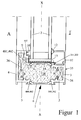
- FIG 1 is an example of a cross section through a fixed glazing made of fire-resistant Profile components 1 shown, wherein I the inside and A the Inscribed on the outside.
- the fixed glazing consists of a frame R (cf. Fig. 6) joined sections of the profile components 1 and fire protection glazing 2.
- the profile component 1 consists of an essentially U-shaped Inner tray 3 and a substantially U-shaped outer tray 4, which are made, for example, of extruded aluminum.
- the interior and Outer support shell 3, 4 face each other with their side legs 5 and point towards the inside I or outside A.
- the thermally separating insulating webs 6 Take up the curl in a positive and positive manner.
- the insulating webs 6 have the Characteristic that they are poorly heat-conducting and under the influence of heat melt.
- the profile component 1 with the inner shell 3 and outer shell 4 and the insulating webs 6 form a single-chamber aluminum composite profile 35, encloses a single hollow chamber H which is covered with a fire protection insulating compound 7 is filled.
- the fire protection insulation 7 is with the inner shell 3 and External support shell 4 connected positively or positively and non-positively.
- the Insulating webs 6 and the side legs 5 of the inner and outer support shell 3, 4 can in the depth transverse to the X-X axis are executed at different depths; hereby the fire resistance period can be controlled.
- the fire protection insulating material 7 consists of a material that melts when melted a carrying case 3 or 4, the opposite carrying case 3 or 4 before exceeding of the temperatures specified in the standards. This is achieved in that the insulating compound 7 as an insulating block in front of the inner or outer support shell 3 or 4 facing away from the fire and the fire protection insulating material 7 releases crystalline water under the influence of heat, so that entire supporting profile 3 or 4 cooled together with the fire protection insulating compound 7 becomes.
- a metallic wire mesh can also be used to improve the load-bearing capacity 8 are inserted into the fire protection insulating compound 7 as a moning.
- the glazing 2 formed from fire protection glass is held for the Normal case (not the case of fire) in a known manner in that the formed Profile component 1 has an approximately L-shaped cross section with a glass abutment 9 in parallel to the X-X axis, in which a groove 405 for receiving the outer Glass seal 10 is molded.
- a groove 405 for receiving the outer Glass seal 10 is molded on the inside I of the profile component 1
- Fire protection glass 2 held by a glass strip 11 which is in a groove in a Side leg 5 of the inner support shell 3 is provided, inserted and through an inner glass seal 12 is fixed.
- the holder of the fire protection glass 2 in the event of a fire is carried out by metallic molded parts 13, which are preferably in the form of pieces made of stainless steel.
- the metallic moldings 13 can have a width of 2 to 5 cm.
- the distance the molded parts can be between 20 and 100 cm. The higher the fire resistance duration the smaller the distance becomes.
- the thickness of the molded part 13 is between 0.5 and 2 mm.
- a frame 15 is together with a sash 16 on the Lock side of a single-leaf door shown, between which a revolving Folding chamber F is formed.
- the door lock 17 in the casement 16 is with a Connecting strap 18 by means of screws on the inner and outer support shell 3, 4 attached.
- the anchor part 20 is on the frame 15 each by means of screws on the inside and External support shell 3, 4 attached.
- FIG 3 is the area of a middle cuff of a two-leaf door with two juxtaposed posts of casement frames 16 and 23 are shown.
- the sash 16 with the door lock 17 corresponds to the embodiment of Figure 2
- the Post of the sash or sash 23 contains in the fire insulation 7 in the middle is an existing one made of plastic or metal Guide tube 24 for receiving a locking bar 25.
- the locking bar 25 serves in Connection to the driving bolt lock 26 for locking the casement 23.
- the guide tube 24 is centered in the fire protection insulating compound 7 and thus roughly in the neutral bending zone, so that if the Casement 23, which arises in the event of fire, the fire protection insulation 7 not is additionally loaded with tensions which cause the block to burst out of the Fire protection insulation 7 can lead.
- the guide tube 24 with the locking bar 25 also in the casement 16 for additional locking e.g. a door active leaf can be used.
- FIG. 4 shows a framework which corresponds in structure to FIG. 2.
- the profile formation is advantageously designed so that the framework as an openable window of fire protection class F30, F60 and F90 in one External facade can be used.
- the profile design advantageously designed so that the rebate space between the window frame 27 and the window casement 28 in the area of respective outer support shell 4 is enlarged, so that in a receiving groove 29a Side leg of the outer shell 4 of the window frame 27 a center bar seal 29 can be pinched, the upper lip of one Stop edge of the outer support shell 4 of the window casement 28 abuts and thus ensuring wind and rain tightness.
- When water enters the drainage chamber 31 the water through the drain hole 32 again directed outside.
- the drainage hole 32 is in a known manner with a Rain cap 30 covered.
- the fitting installation, the glass bracket and the anchorages are carried out as described in Figure 2.
- FIG. 1 An alternative holder for the fire protection glass 2 is shown in FIG.
- the metallic retaining strip shows a U-shaped cross-sectional design with two side legs 33a and one these connecting base legs 33b.
- the side legs 33a are with a continuous hollow chamber formed, for. B. made of appropriate steel pipes.
- the side legs 33a are attached by means of screws (not shown here) attached to the bottom leg 33b.
- the bottom leg 33b is about 2 to 5 cm wide and is attached at a distance of about 20 to 100 cm.
- the thickness of the bottom leg 33b is approximately 2 to 5 mm.
- the distance and number of floor legs 33b depend on the fire resistance duration.
- the bottom legs 33b are each by screws on the side legs 5 of the aluminum interior and External trays 3, 4 attached. According to the invention, this glass holder achieved that regardless of the direction of fire, the additional glass bracket is always attached to a support shell 3 or 4 facing away from the fire.
- FIG. 6 schematically shows the production of a frame R, as it is, for example for the formation of those used in the figures explained above Frame and / or casement for the formation of windows, doors, wall elements, Facades and the like can be used shown.
- profile components with the structure explained above are made essentially U-shaped extruded aluminum sections, each form an inner support shell 3 and an outer support shell 4 and at their free Leg ends by means of thermally separating insulating webs 6 into a single one Hollow chamber H surrounding composite profile 35 prefabricated and into individual frame sections, that are identified in FIG. 6 by reference numbers R1, R2, R3 and R4 are cut to length.
- the fire protection insulation 7 at least partially, as one or more of the whole or a partial cross section of the hollow chamber H shaped part (s) is introduced, which is illustrated in the drawing by reference numeral 36 is.
- the frame consists of the frame sections R1 to R4 in the manner is composed that the in the respective frame sections R1 to R4 surrounded by the composite profile 35 hollow chamber and continuing through the entire frame R is guided, a single insertion of a hole is sufficient B or from two holes B, E in the frame R to the entire circumferential To be able to fill hollow chamber H with fire protection insulating compound 7.
- corner connectors in the Transitional areas between adjacent frame sections R1, R2, R3, R4 are used, one for each frame section R1 to R4 Bore B for filling the fire protection insulating compound 7 and one bore E each introduced to escape the contained air and thus each frame section R1 to R4 of the frame R are filled separately with the fire protection insulating compound 7.
- a major advantage of the method described above is that cutting the profile sections to length before filling them with the fire protection insulating compound 7 takes place. Since in this case only aluminum (the outer and inner support shell 3, 4) and plastic (the insulating webs 6) must be cut, this can be done conventional sawing devices without much effort and wear carry out. A filling with already completed at this time Fire protection insulation 7, however, due to the additional to be cut Fire protection insulating material 7 very high saw wear, the invention is avoided.
- Figure 7 corresponds essentially to Figure 1.
- 4 before filling the Profiles with fire protection insulation 7 in the aluminum trays 3, 4 at least a molded part (not shown) inserted after filling and curing the fire protection insulating material 7 pulled out of the profile component 1 again can be, so that in the single hollow chamber H at least one (in Case two shown) partial chamber (s) not filled with fire protection insulating compound 7 37 remain.
- This method has the advantage that the profiles on the rod can be filled and the unfilled subchambers 37 for connecting the Profiles with a corner bracket (corner connector) can be used.
- Figure 8 corresponds essentially to Figure 2.
- the only one Hollow chamber H at least one (again two in the case shown) partial chamber (s) 37 filled with fire protection insulating compound 7 are provided. additionally is in the middle of the profile component 1, e.g. thermal insulation made of mineral wool 38 used.
- This insulation 38 fulfills the purpose that at Use of the profile components 1 in an outdoor area in addition to fire resistance a good heat-insulating effect of the profile component can also be achieved.
- the fire protection insulation 7 - as shown - with a Reinforcement 39 are reinforced.
- Thermal insulation 38 and / or reinforcement 39 can of course also be filled in regardless of the presence Subchambers 37 are provided. They also come with this version aforementioned manufacturing advantages to bear.
- Figure 9 illustrates two other ways to accomplish that in the single hollow chamber H partial chamber (s) not filled with fire protection insulating compound 7 37 remain.
- an adhesive tape 40 in the Profile component 1 glued.
- the adhesive tape 40 closes the filled part of the Hollow chamber H against the unfilled partial chamber 37.
- Gluing the Adhesive tape 40 is before connecting the inner tray 3 and the Outer support shell 4 through the insulating webs 6 and before filling the profile component 1 made with fire protection insulating compound 7.
- the adhesive tape 40 prevents one Filling of sub-chamber 37 with fire protection insulating compound 7.
- After filling the adhesive tape 40 remains in the profile.
- the adhesive tape 40 is preferably two protruding into the hollow chamber H, facing each other at a distance L.
- Legs 41, 42 of the inner support shell 3 are glued and bridge the distance L. between the legs 41, 42.
- the adhesive tape 40 is in each case in contact Side walls of the legs 41, 42, which with the 7 fire insulation filled or initially to be filled part of the hollow chamber H are facing. This can cause it under the pressure of the fire protection insulating material 7 Do not loosen the filling, but press it even more firmly.
- An adhesive tape 40 could can of course also be provided analogously on the outer support shell 4.
- FIG. 9 there are two opposite L at a distance Legs 43, 44 of the outer support shell 4 are a molded plastic body 45 pushed.
- the molded plastic body 45 closes the filled part of the hollow chamber H against the unfilled partial chamber 37. Sliding on the molded plastic body 45 is before or after connecting the inner support shell 3 and External tray 4 through the insulating webs 6, but in any case before filling the Profile component 1 made with fire protection insulating material 7, whereby the distance L is bridged between the legs 43, 44.
- the plastic molded body 45 prevents the partial chamber 37 from being filled with fire protection insulating compound 7. After after filling, it remains in the profile.
- the plastic molded body 45 under the pressure of the fire protection insulating material 7 can not solve when filling, it includes form-fitting the free ends of the legs 43, 44. For this is on the two A groove 406 is provided on each of the long sides of the shaped body 45.
- a plastic molded body 45 could of course also analogously on the inner tray 3 be provided.
- the fire protection insulating compound 7 all or part of a magnesium oxychloride cement, if necessary also contains magnesium sulfate. This feature as well as those given above Compositions that differ from the stoichiometry of the setting derived reactions, is - as already mentioned - also inventive Attached importance.
- part of the magnesium chloride used to manufacture the fire protection insulating material 7 can be replaced by a metal chloride, such as calcium chloride, the cation of which forms sparingly soluble sulfates.
- a sedimentation reaction according to the equation runs during the production of the insulating compound 7 CaCl 2 + MgSO 4 ---> MgCl 2 + CaSO 4 ⁇ from, in which the magnesium chloride is formed in the manufacturing process itself from the other metal chloride.
- the precipitated, poorly soluble metal sulfate, in the illustrated case gypsum can act as a filler in the hardened insulating compound 7, but can also contribute to a further improvement in properties.
- the fire protection insulation 7 contains water glass, in particular sodium water glass, this results in greater strength and water resistance and in an increased fire resistance of the composition.
- the sodium water glass has a composition with an average molar Na 2 O / SiO 2 ratio of 1: (1.5 to 4.0) and if the sodium water glass is initially liquid in the insulating compound 7 is introduced, it should have a density of about 1.32 to 1.55 g / cm 3 .
- the amount of water glass introduced into the insulating compound 7 should be selected such that the magnesium oxychloride cement or magnesium oxychloride-magnesium oxysulfate cement has a composition with an average molar ratio of MgCl 2 to soda water glass of approximately 1: (0.02 to 0.35) having.
- the insulating compound 7 contains silica contains. This can e.g. can be added as an amorphous powder.
- silica in the insulating compound 7 brings about similar improvements in properties like that of water glass, but it increases its effectiveness.
- silica is a collective name for compounds that Silicon dioxide and different proportions of water can contain. So a distinction is made between orthosilicic acid, different types of polysilicic acids and Metasilicic acids and finally the so-called phyllodic silica, whereby the mentioned silicas by an increasing in the order given Characterize degree of condensation and decreasing water content and in the final stage the condensation occurring to form chain molecules is almost anhydrous Silicon dioxide is created.
- Silicic acid can be precipitated by means of metal salt and / or acid from water glass are generated, with a low degree of condensation they are initially used as (liquid) Hydrosol is present and at an appropriate temperature (starting at Room temperature or a little above) and at an appropriate pH value (greater or less than about 3.1-3.3) an envelope of the colloidally disperse silica particles uses, which can lead to gel formation.
- the silica is higher in a network and / or honeycomb structure specific surface and porosity arranged in the water.
- the circumstance of the sol-gel reaction can be used according to the invention by the silica through Precipitation using metal salt and / or acid from the insulating compound 7 initially contained water glass is generated. This advantageously results on the one hand an increase in strength and fire resistance, and on the other hand, the Shrinkage amount of the curing insulating compound 7 is reduced.
- the fire protection insulation 7 is - as stated - in the flowable state in the Hollow chamber H introduced.
- a magnesium oxychloride cement a fire protection insulation 7 used, which from a Mixture of magnesium oxide (reactively fired magnesia) and concentrated, in particular saturated or supersaturated, aqueous magnesium chloride solution is produced and also produced with the addition of magnesium sulfate can be.
- a metal chloride such as Calcium chloride, the cation of which forms poorly soluble sulfates, such as calcium sulfate.
- the insulating compound 7 can also with the addition of water glass, in particular Sodium water glass in liquid solution, preferably two Partial mixtures, one of the starting materials mentioned for the magnesium oxychloride cement and another from the water glass, if necessary mixed with magnesium sulfate, to be stirred into a highly viscous suspension.
- water glass in particular Sodium water glass in liquid solution, preferably two Partial mixtures, one of the starting materials mentioned for the magnesium oxychloride cement and another from the water glass, if necessary mixed with magnesium sulfate, to be stirred into a highly viscous suspension.
- the insulating compound 7 can also contain silica, which is preferably produced in the manufacturing process of the insulating compound 7 by precipitation from water glass using acid or salt. Mineral and / or organic acids can be used to set a suitable pH.
- a fire resistance class of up to F120 can be achieved.
- the invention is limited not to the various illustrated embodiments, but also includes all equivalent designs.
- the person skilled in the art can additional others provide advantageous measures, such as the admixture of fillers or pigments for fire protection insulation 7, in particular zinc oxide, Titanium oxide and aluminum oxide are particularly suitable.
- an embedding reinforcing parts or materials, such as glass fibers or a fabric made of plastic, wire, glass fibers or the like, into the fire protection insulating compound 7 can be provided as a measure that reinforces the advantages of the invention.
Landscapes
- Engineering & Computer Science (AREA)
- Civil Engineering (AREA)
- Structural Engineering (AREA)
- Physics & Mathematics (AREA)
- Architecture (AREA)
- Electromagnetism (AREA)
- Thermal Sciences (AREA)
- Special Wing (AREA)
- Building Environments (AREA)
Priority Applications (5)
| Application Number | Priority Date | Filing Date | Title |
|---|---|---|---|
| EP02797967A EP1425492B1 (fr) | 2001-09-10 | 2002-09-09 | Element profile refractaire et procede permettant de le produire |
| PCT/EP2002/010060 WO2003023175A1 (fr) | 2001-09-10 | 2002-09-09 | Element profile refractaire et procede permettant de le produire |
| AT02797967T ATE384187T1 (de) | 2001-09-10 | 2002-09-09 | Feuerwiderstandsfähiges profilbauteil und verfahren zu seiner herstellung |
| DE50211563T DE50211563D1 (de) | 2001-09-10 | 2002-09-09 | Feuerwiderstandsfähiges profilbauteil und verfahren zu seiner herstellung |
| PL367822A PL203004B1 (pl) | 2001-09-10 | 2002-09-09 | Ognioodporny profilowy element konstrukcyjny i sposób jego wytwarzania oraz okno albo drzwi wykonane z ognioodpornego profilowego elementu konstrukcyjnego i sposób jego wytwarzania |
Applications Claiming Priority (4)
| Application Number | Priority Date | Filing Date | Title |
|---|---|---|---|
| DE20111298U | 2001-07-07 | ||
| DE20111298 | 2001-07-07 | ||
| DE20114949U DE20114949U1 (de) | 2001-07-07 | 2001-09-10 | Feuerwiderstandsfähiges Profilbauteil |
| DE20114949U | 2001-09-10 |
Publications (2)
| Publication Number | Publication Date |
|---|---|
| EP1296013A1 true EP1296013A1 (fr) | 2003-03-26 |
| EP1296013B1 EP1296013B1 (fr) | 2004-10-27 |
Family
ID=26057086
Family Applications (1)
| Application Number | Title | Priority Date | Filing Date |
|---|---|---|---|
| EP20020005502 Expired - Lifetime EP1296013B1 (fr) | 2001-07-07 | 2002-03-11 | Profilé de construction résistant au feu et procédé pour sa fabrication |
Country Status (2)
| Country | Link |
|---|---|
| EP (1) | EP1296013B1 (fr) |
| AT (1) | ATE280884T1 (fr) |
Cited By (6)
| Publication number | Priority date | Publication date | Assignee | Title |
|---|---|---|---|---|
| EP1970522A2 (fr) | 2007-03-14 | 2008-09-17 | Reynaers Aluminium, naamloze vennootschap | Ébénisterie pour fenêtre et portes, ou similaire, et élément d'insert appliqué à une telle ébénisterie |
| CH703403A1 (de) * | 2010-07-06 | 2012-01-13 | Swissstarsysteme Ag | Rahmen. |
| EP2910724A1 (fr) * | 2014-02-20 | 2015-08-26 | Evonik Degussa GmbH | Cadre rempli de matière thermo-isolante et son procédé de fabrication |
| CN106593197A (zh) * | 2017-02-24 | 2017-04-26 | 黄连欣 | 一种铝合金耐火型材 |
| EP3450671A1 (fr) * | 2017-08-29 | 2019-03-06 | Hörmann KG Glastechnik | Procédé de fabrication d'éléments de fermeture de protection contre les incendies avec et sans vitrage ainsi que série d'éléments de fermeture de protection contre les incendies |
| EP3636869A1 (fr) * | 2018-10-12 | 2020-04-15 | heroal- Johann Henkenjohann GmbH & Co. KG | Profilé creux à chambres multiples pour portes ou fenêtres de protection contre l'incendie, procédé ainsi que dispositif de fabrication d'un tel profilé creux à chambres multiples |
Families Citing this family (1)
| Publication number | Priority date | Publication date | Assignee | Title |
|---|---|---|---|---|
| US10759697B1 (en) | 2019-06-11 | 2020-09-01 | MSB Global, Inc. | Curable formulations for structural and non-structural applications |
Citations (9)
| Publication number | Priority date | Publication date | Assignee | Title |
|---|---|---|---|---|
| FR2465863A1 (fr) * | 1979-09-22 | 1981-03-27 | Hueck Fa E | Profile composite isolant pour fenetres, portes et ouvrages analogues, en particulier pour fenetres coulissantes, et son procede de fabrication |
| US4364987A (en) * | 1981-05-14 | 1982-12-21 | Cawm-Crete International Limited | Fire door construction |
| EP0485867A2 (fr) * | 1990-11-13 | 1992-05-20 | Grünzweig + Hartmann AG | Composition retardratice de feu à base d'hydroxyde métallique et de liant magnésien et utilisation |
| DE4443762A1 (de) | 1994-12-08 | 1996-06-13 | Schueco Int Kg | Rahmenwerk aus Metallprofilen in Brandschutzausführung für Fenster, Türen, Fassaden oder Glasdächer |
| EP0741003A1 (fr) * | 1995-05-05 | 1996-11-06 | Grünzweig + Hartmann AG | Elément stratifié de protection contre le feu, en particulier comme pièce intercalaire pour portes coupe-feu ainsi que le demi-produit utilisé à cet effet |
| WO1997007315A1 (fr) * | 1995-08-21 | 1997-02-27 | Glostal Limited | Ameliorations apportees a des ecrans pare-feu ou s'y rapportant |
| EP0785334A2 (fr) | 1992-09-26 | 1997-07-23 | TRUBE & KINGS KG | Elément de construction coupe-feu |
| DE9321360U1 (de) * | 1992-09-26 | 1997-08-28 | Trube & Kings KG, 56767 Uersfeld | Feuerhemmendes Bauteil |
| EP0927809A2 (fr) * | 1997-12-19 | 1999-07-07 | Skandinaviska Aluminium Profiler Ab | Elément de construction coupe-feu |
-
2002
- 2002-03-11 AT AT02005502T patent/ATE280884T1/de active
- 2002-03-11 EP EP20020005502 patent/EP1296013B1/fr not_active Expired - Lifetime
Patent Citations (10)
| Publication number | Priority date | Publication date | Assignee | Title |
|---|---|---|---|---|
| FR2465863A1 (fr) * | 1979-09-22 | 1981-03-27 | Hueck Fa E | Profile composite isolant pour fenetres, portes et ouvrages analogues, en particulier pour fenetres coulissantes, et son procede de fabrication |
| US4364987A (en) * | 1981-05-14 | 1982-12-21 | Cawm-Crete International Limited | Fire door construction |
| EP0485867A2 (fr) * | 1990-11-13 | 1992-05-20 | Grünzweig + Hartmann AG | Composition retardratice de feu à base d'hydroxyde métallique et de liant magnésien et utilisation |
| EP0785334A2 (fr) | 1992-09-26 | 1997-07-23 | TRUBE & KINGS KG | Elément de construction coupe-feu |
| DE9321360U1 (de) * | 1992-09-26 | 1997-08-28 | Trube & Kings KG, 56767 Uersfeld | Feuerhemmendes Bauteil |
| DE4443762A1 (de) | 1994-12-08 | 1996-06-13 | Schueco Int Kg | Rahmenwerk aus Metallprofilen in Brandschutzausführung für Fenster, Türen, Fassaden oder Glasdächer |
| EP0717165A1 (fr) | 1994-12-08 | 1996-06-19 | SCHÜCO International KG | Ossature de profiles métalliques ignifuges pour fenêtres, portes, façades ou toits vitrés |
| EP0741003A1 (fr) * | 1995-05-05 | 1996-11-06 | Grünzweig + Hartmann AG | Elément stratifié de protection contre le feu, en particulier comme pièce intercalaire pour portes coupe-feu ainsi que le demi-produit utilisé à cet effet |
| WO1997007315A1 (fr) * | 1995-08-21 | 1997-02-27 | Glostal Limited | Ameliorations apportees a des ecrans pare-feu ou s'y rapportant |
| EP0927809A2 (fr) * | 1997-12-19 | 1999-07-07 | Skandinaviska Aluminium Profiler Ab | Elément de construction coupe-feu |
Cited By (8)
| Publication number | Priority date | Publication date | Assignee | Title |
|---|---|---|---|---|
| EP1970522A2 (fr) | 2007-03-14 | 2008-09-17 | Reynaers Aluminium, naamloze vennootschap | Ébénisterie pour fenêtre et portes, ou similaire, et élément d'insert appliqué à une telle ébénisterie |
| EP1970522A3 (fr) * | 2007-03-14 | 2008-12-24 | Reynaers Aluminium, naamloze vennootschap | Ébénisterie pour fenêtre et portes, ou similaire, et élément d'insert appliqué à une telle ébénisterie |
| CH703403A1 (de) * | 2010-07-06 | 2012-01-13 | Swissstarsysteme Ag | Rahmen. |
| EP2910724A1 (fr) * | 2014-02-20 | 2015-08-26 | Evonik Degussa GmbH | Cadre rempli de matière thermo-isolante et son procédé de fabrication |
| EP3128113A1 (fr) * | 2014-02-20 | 2017-02-08 | Evonik Degussa GmbH | Cadre rempli de matière thermo-isolante et son procédé de fabrication |
| CN106593197A (zh) * | 2017-02-24 | 2017-04-26 | 黄连欣 | 一种铝合金耐火型材 |
| EP3450671A1 (fr) * | 2017-08-29 | 2019-03-06 | Hörmann KG Glastechnik | Procédé de fabrication d'éléments de fermeture de protection contre les incendies avec et sans vitrage ainsi que série d'éléments de fermeture de protection contre les incendies |
| EP3636869A1 (fr) * | 2018-10-12 | 2020-04-15 | heroal- Johann Henkenjohann GmbH & Co. KG | Profilé creux à chambres multiples pour portes ou fenêtres de protection contre l'incendie, procédé ainsi que dispositif de fabrication d'un tel profilé creux à chambres multiples |
Also Published As
| Publication number | Publication date |
|---|---|
| EP1296013B1 (fr) | 2004-10-27 |
| ATE280884T1 (de) | 2004-11-15 |
Similar Documents
| Publication | Publication Date | Title |
|---|---|---|
| EP0590236B1 (fr) | Elément de construction coupe-feu | |
| DE3009729A1 (de) | Bauteil (bauelement) | |
| EP1097807B2 (fr) | Produit pour la protection contre le feu à base de laine minérale lié et élément pour la protection contre le feu comprenant ledit produit | |
| DE10144820A1 (de) | Brandschutzelement, Verfahren zu dessen Herstellung und brandschutzgesichertes Rahmenwerk für ein Gebäudeteil, wie für eine Gebäudefassade oder dgl. | |
| DE20114949U1 (de) | Feuerwiderstandsfähiges Profilbauteil | |
| EP1296013B1 (fr) | Profilé de construction résistant au feu et procédé pour sa fabrication | |
| DE102018121776A1 (de) | Zarge für Fenster und Türen sowie Fenster- oder Türelement mit einer solchen | |
| EP2072748A2 (fr) | Elément de réception pour un système d'ombrage | |
| EP2620567A2 (fr) | Système composite d'isolation thermique avec une barrière ignifuge, élément d'isolation thermique et utilisation de l'élément d'isolation thermique comme barrière ignifuge | |
| DE10144551A1 (de) | Brandschutzelement, Verfahren zu dessen Herstellung und brandschutzgesichertes Rahmenwerk für ein Gebäudeteil, wie für eine Gebäudefassade oder dgl. | |
| EP3122956A1 (fr) | Brique d'isolation pour mur multicouche, mur multicouche pourvu d'une telle brique et bâtiment formé à un tel mur et procédé d'érection d'un mur multicouche | |
| DE2734513A1 (de) | Baublock | |
| WO2003023175A1 (fr) | Element profile refractaire et procede permettant de le produire | |
| DE19643618A1 (de) | Wärmedämmverbundsystem | |
| DE3414388C2 (fr) | ||
| DE9321360U1 (de) | Feuerhemmendes Bauteil | |
| EP1425492B1 (fr) | Element profile refractaire et procede permettant de le produire | |
| DE9211944U1 (de) | Feuerschutzabschluß im Gebäudebereich | |
| DE19860974C1 (de) | Wärme-und/oder Schalldämmelement | |
| DE4443761A1 (de) | Wärmebindendes Bauteil für den Innen- und Außenausbau in Brandschutzausführung | |
| EP2535473A2 (fr) | Système pare-feu ainsi que porte coupe-feu, élément mural pare-feu et panneau coupe-feu à cet effet | |
| AT385899B (de) | Anordnung zur im brandfall wirksamen abdichtung von oeffnungen in bauteilen | |
| DE102018125362A1 (de) | Mehrkammerhohlprofil für Brandschutztüren oder -fenster und Verfahren sowie Vorrichtung zum Herstellen eines solchen Mehrkammerhohlprofils | |
| EP1445389A2 (fr) | Elément de façade et procédé pour sa fabrication | |
| DE202012104974U1 (de) | Dämmelement |
Legal Events
| Date | Code | Title | Description |
|---|---|---|---|
| PUAI | Public reference made under article 153(3) epc to a published international application that has entered the european phase |
Free format text: ORIGINAL CODE: 0009012 |
|
| AK | Designated contracting states |
Designated state(s): AT BE CH CY DE DK ES FI FR GB GR IE IT LI LU MC NL PT SE TR Kind code of ref document: A1 Designated state(s): AT BE CH CY DE DK ES FI FR GB GR IE IT LI LU MC NL PT SE TR |
|
| AX | Request for extension of the european patent |
Extension state: AL LT LV MK RO SI |
|
| 17P | Request for examination filed |
Effective date: 20030820 |
|
| AKX | Designation fees paid |
Designated state(s): AT BE CH CY DE DK ES FI FR GB GR IE IT LI LU MC NL PT SE TR |
|
| 17Q | First examination report despatched |
Effective date: 20031114 |
|
| GRAP | Despatch of communication of intention to grant a patent |
Free format text: ORIGINAL CODE: EPIDOSNIGR1 |
|
| GRAS | Grant fee paid |
Free format text: ORIGINAL CODE: EPIDOSNIGR3 |
|
| GRAA | (expected) grant |
Free format text: ORIGINAL CODE: 0009210 |
|
| RAP1 | Party data changed (applicant data changed or rights of an application transferred) |
Owner name: BEMO BRANDSCHUTZSYSTEME GMBH |
|
| AK | Designated contracting states |
Kind code of ref document: B1 Designated state(s): AT BE CH CY DE DK ES FI FR GB GR IE IT LI LU MC NL PT SE TR |
|
| PG25 | Lapsed in a contracting state [announced via postgrant information from national office to epo] |
Ref country code: IT Free format text: LAPSE BECAUSE OF FAILURE TO SUBMIT A TRANSLATION OF THE DESCRIPTION OR TO PAY THE FEE WITHIN THE PRESCRIBED TIME-LIMIT;WARNING: LAPSES OF ITALIAN PATENTS WITH EFFECTIVE DATE BEFORE 2007 MAY HAVE OCCURRED AT ANY TIME BEFORE 2007. THE CORRECT EFFECTIVE DATE MAY BE DIFFERENT FROM THE ONE RECORDED. Effective date: 20041027 Ref country code: TR Free format text: LAPSE BECAUSE OF FAILURE TO SUBMIT A TRANSLATION OF THE DESCRIPTION OR TO PAY THE FEE WITHIN THE PRESCRIBED TIME-LIMIT Effective date: 20041027 Ref country code: GB Free format text: LAPSE BECAUSE OF FAILURE TO SUBMIT A TRANSLATION OF THE DESCRIPTION OR TO PAY THE FEE WITHIN THE PRESCRIBED TIME-LIMIT Effective date: 20041027 Ref country code: FI Free format text: LAPSE BECAUSE OF FAILURE TO SUBMIT A TRANSLATION OF THE DESCRIPTION OR TO PAY THE FEE WITHIN THE PRESCRIBED TIME-LIMIT Effective date: 20041027 Ref country code: IE Free format text: LAPSE BECAUSE OF FAILURE TO SUBMIT A TRANSLATION OF THE DESCRIPTION OR TO PAY THE FEE WITHIN THE PRESCRIBED TIME-LIMIT Effective date: 20041027 Ref country code: NL Free format text: LAPSE BECAUSE OF FAILURE TO SUBMIT A TRANSLATION OF THE DESCRIPTION OR TO PAY THE FEE WITHIN THE PRESCRIBED TIME-LIMIT Effective date: 20041027 |
|
| REG | Reference to a national code |
Ref country code: GB Ref legal event code: FG4D Free format text: NOT ENGLISH |
|
| REG | Reference to a national code |
Ref country code: CH Ref legal event code: EP |
|
| REG | Reference to a national code |
Ref country code: IE Ref legal event code: FG4D Free format text: GERMAN |
|
| REF | Corresponds to: |
Ref document number: 50201392 Country of ref document: DE Date of ref document: 20041202 Kind code of ref document: P |
|
| PG25 | Lapsed in a contracting state [announced via postgrant information from national office to epo] |
Ref country code: DK Free format text: LAPSE BECAUSE OF FAILURE TO SUBMIT A TRANSLATION OF THE DESCRIPTION OR TO PAY THE FEE WITHIN THE PRESCRIBED TIME-LIMIT Effective date: 20050127 Ref country code: GR Free format text: LAPSE BECAUSE OF FAILURE TO SUBMIT A TRANSLATION OF THE DESCRIPTION OR TO PAY THE FEE WITHIN THE PRESCRIBED TIME-LIMIT Effective date: 20050127 Ref country code: SE Free format text: LAPSE BECAUSE OF FAILURE TO SUBMIT A TRANSLATION OF THE DESCRIPTION OR TO PAY THE FEE WITHIN THE PRESCRIBED TIME-LIMIT Effective date: 20050127 |
|
| PG25 | Lapsed in a contracting state [announced via postgrant information from national office to epo] |
Ref country code: ES Free format text: LAPSE BECAUSE OF FAILURE TO SUBMIT A TRANSLATION OF THE DESCRIPTION OR TO PAY THE FEE WITHIN THE PRESCRIBED TIME-LIMIT Effective date: 20050207 |
|
| REG | Reference to a national code |
Ref country code: CH Ref legal event code: NV Representative=s name: BRAUNPAT BRAUN EDER AG |
|
| PG25 | Lapsed in a contracting state [announced via postgrant information from national office to epo] |
Ref country code: LU Free format text: LAPSE BECAUSE OF NON-PAYMENT OF DUE FEES Effective date: 20050311 Ref country code: CY Free format text: LAPSE BECAUSE OF FAILURE TO SUBMIT A TRANSLATION OF THE DESCRIPTION OR TO PAY THE FEE WITHIN THE PRESCRIBED TIME-LIMIT Effective date: 20050311 |
|
| PG25 | Lapsed in a contracting state [announced via postgrant information from national office to epo] |
Ref country code: MC Free format text: LAPSE BECAUSE OF NON-PAYMENT OF DUE FEES Effective date: 20050331 Ref country code: BE Free format text: LAPSE BECAUSE OF NON-PAYMENT OF DUE FEES Effective date: 20050331 |
|
| NLV1 | Nl: lapsed or annulled due to failure to fulfill the requirements of art. 29p and 29m of the patents act | ||
| REG | Reference to a national code |
Ref country code: IE Ref legal event code: FD4D |
|
| GBV | Gb: ep patent (uk) treated as always having been void in accordance with gb section 77(7)/1977 [no translation filed] |
Effective date: 20041027 |
|
| PLBE | No opposition filed within time limit |
Free format text: ORIGINAL CODE: 0009261 |
|
| STAA | Information on the status of an ep patent application or granted ep patent |
Free format text: STATUS: NO OPPOSITION FILED WITHIN TIME LIMIT |
|
| BERE | Be: lapsed |
Owner name: BEMO BRANDSCHUTZSYSTEME G.M.B.H. Effective date: 20050331 |
|
| 26N | No opposition filed |
Effective date: 20050728 |
|
| ET | Fr: translation filed | ||
| BERE | Be: lapsed |
Owner name: *BEMO BRANDSCHUTZSYSTEME G.M.B.H. Effective date: 20050331 |
|
| PG25 | Lapsed in a contracting state [announced via postgrant information from national office to epo] |
Ref country code: PT Free format text: LAPSE BECAUSE OF NON-PAYMENT OF DUE FEES Effective date: 20050327 |
|
| REG | Reference to a national code |
Ref country code: CH Ref legal event code: PUE Owner name: NOVOFERM GMBH Free format text: BEMO BRANDSCHUTZSYSTEME GMBH#KAERLICHERSTRASSE#56575 WEISSENTHURM (DE) -TRANSFER TO- NOVOFERM GMBH#ISSELBURGER STRASSE 31#46459 REES (DE) |
|
| REG | Reference to a national code |
Ref country code: FR Ref legal event code: TP |
|
| REG | Reference to a national code |
Ref country code: FR Ref legal event code: PLFP Year of fee payment: 14 |
|
| PGFP | Annual fee paid to national office [announced via postgrant information from national office to epo] |
Ref country code: CH Payment date: 20150313 Year of fee payment: 14 |
|
| PGFP | Annual fee paid to national office [announced via postgrant information from national office to epo] |
Ref country code: AT Payment date: 20150309 Year of fee payment: 14 Ref country code: FR Payment date: 20150309 Year of fee payment: 14 |
|
| PGFP | Annual fee paid to national office [announced via postgrant information from national office to epo] |
Ref country code: DE Payment date: 20150527 Year of fee payment: 14 |
|
| REG | Reference to a national code |
Ref country code: DE Ref legal event code: R119 Ref document number: 50201392 Country of ref document: DE |
|
| REG | Reference to a national code |
Ref country code: CH Ref legal event code: PL |
|
| REG | Reference to a national code |
Ref country code: AT Ref legal event code: MM01 Ref document number: 280884 Country of ref document: AT Kind code of ref document: T Effective date: 20160311 |
|
| REG | Reference to a national code |
Ref country code: FR Ref legal event code: ST Effective date: 20161130 |
|
| PG25 | Lapsed in a contracting state [announced via postgrant information from national office to epo] |
Ref country code: LI Free format text: LAPSE BECAUSE OF NON-PAYMENT OF DUE FEES Effective date: 20160331 Ref country code: CH Free format text: LAPSE BECAUSE OF NON-PAYMENT OF DUE FEES Effective date: 20160331 Ref country code: DE Free format text: LAPSE BECAUSE OF NON-PAYMENT OF DUE FEES Effective date: 20161001 Ref country code: FR Free format text: LAPSE BECAUSE OF NON-PAYMENT OF DUE FEES Effective date: 20160331 |
|
| PG25 | Lapsed in a contracting state [announced via postgrant information from national office to epo] |
Ref country code: AT Free format text: LAPSE BECAUSE OF NON-PAYMENT OF DUE FEES Effective date: 20160311 |