EP1296055A2 - Brennstoffeinspritzventil mit drosselnder Lochplatte - Google Patents
Brennstoffeinspritzventil mit drosselnder Lochplatte Download PDFInfo
- Publication number
- EP1296055A2 EP1296055A2 EP02020960A EP02020960A EP1296055A2 EP 1296055 A2 EP1296055 A2 EP 1296055A2 EP 02020960 A EP02020960 A EP 02020960A EP 02020960 A EP02020960 A EP 02020960A EP 1296055 A2 EP1296055 A2 EP 1296055A2
- Authority
- EP
- European Patent Office
- Prior art keywords
- passage
- fuel
- control chamber
- plate
- pressure control
- Prior art date
- Legal status (The legal status is an assumption and is not a legal conclusion. Google has not performed a legal analysis and makes no representation as to the accuracy of the status listed.)
- Granted
Links
Images


Classifications
-
- F—MECHANICAL ENGINEERING; LIGHTING; HEATING; WEAPONS; BLASTING
- F02—COMBUSTION ENGINES; HOT-GAS OR COMBUSTION-PRODUCT ENGINE PLANTS
- F02M—SUPPLYING COMBUSTION ENGINES IN GENERAL WITH COMBUSTIBLE MIXTURES OR CONSTITUENTS THEREOF
- F02M61/00—Fuel-injectors not provided for in groups F02M39/00 - F02M57/00 or F02M67/00
- F02M61/16—Details not provided for in, or of interest apart from, the apparatus of groups F02M61/02 - F02M61/14
- F02M61/168—Assembling; Disassembling; Manufacturing; Adjusting
-
- F—MECHANICAL ENGINEERING; LIGHTING; HEATING; WEAPONS; BLASTING
- F02—COMBUSTION ENGINES; HOT-GAS OR COMBUSTION-PRODUCT ENGINE PLANTS
- F02M—SUPPLYING COMBUSTION ENGINES IN GENERAL WITH COMBUSTIBLE MIXTURES OR CONSTITUENTS THEREOF
- F02M47/00—Fuel-injection apparatus operated cyclically with fuel-injection valves actuated by fluid pressure
- F02M47/02—Fuel-injection apparatus operated cyclically with fuel-injection valves actuated by fluid pressure of accumulator-injector type, i.e. having fuel pressure of accumulator tending to open, and fuel pressure in other chamber tending to close, injection valves and having means for periodically releasing that closing pressure
- F02M47/027—Electrically actuated valves draining the chamber to release the closing pressure
-
- F—MECHANICAL ENGINEERING; LIGHTING; HEATING; WEAPONS; BLASTING
- F02—COMBUSTION ENGINES; HOT-GAS OR COMBUSTION-PRODUCT ENGINE PLANTS
- F02M—SUPPLYING COMBUSTION ENGINES IN GENERAL WITH COMBUSTIBLE MIXTURES OR CONSTITUENTS THEREOF
- F02M2200/00—Details of fuel-injection apparatus, not otherwise provided for
- F02M2200/28—Details of throttles in fuel-injection apparatus
Definitions
- the present invention relates to a fuel injection valve, in which injection amount and injection timing are controlled by changing fuel pressure of a pressure control chamber.
- a common rail fuel injection system in which high pressure fuel accumulated in a common rail is injected into a combustion chamber, is well known.
- Afuel injection valve which is applicable to the common rail fuel injection system, has a pressure control chamber, whose pressure is controlled by fuel supplied thereto through an entrance orifice provided in a fuel flow-in passage and ejected therefrom through an exit orifice provided in a fuel flow-out passage for giving backpressure to a control piston movable together with a needle.
- the injection amount and injection timing are variable based on a change of the fuel pressure of the pressure control chamber (backpressure to the control piston).
- the fuel pressure of the pressure control chamber is changed by an electromagnetic valve that is operative to open and close the fuel flow-out passage including the exit orifice through which the pressure control chamber communicates with a low pressure source.
- a first plate in which the entrance orifice is formed and a second plate in which the exit orifice is formed are different members.
- This causes an inconvenience, on adjusting length of the entrance orifice for securing a target flow amount of fuel, that a change of enlarging the length of the entrance orifice is not sufficiently free, since the entrance orifice is limited to be positioned within the first plate whose thickness is relatively thin. Therefore, in this case, instead of enlarging the length of the entrance orifice, the diameter of the entrance orifice is obliged to be reduced for the adjustment of fuel flow.
- An object of the present invention is to provide a fuel injection valve having a piece of plate in which both of an entrance orifice and an exit orifice are formed so that length of the entrance orifice is easily changed for adjusting a flow amount of fuel passing therethrough to a target value.
- the fuel injection valve having a pressure control chamber to which fuel is supplied from high pressure source via a fuel flow-in passage including an entrance orifice and from which the fuel is ejected to a low pressure source via a fuel flow-out passage including an exit orifice, a nozzle provided with a needle making an axial and reciprocal movement in response to fuel pressure in the pressure control chamber and with an injection hole to be opened and closed by the movement of the needle, and an electromagnetic valve operative to allow and interrupt a fuel communication between the fuel flow-out passage and the low pressure source for controlling the fuel pressure in the pressure control chamber, the fuel flow-in passage, the fuel flow-out passage and at least a part of the pressure control chamber are formed in a single piece of a plate.
- the part of the pressure control chamber is opened to an axial end surface of the plate and the fuel flow-out passage extends so as to penetrate the plate axially from an inner wall of the part of the pressure control chamber to another axial end surface of the plate.
- the fuel flow-in passage comprises a first passage extending from the axial end surface of the plate and a second passage extending from the inner wall of the part of the pressure control chamber, which intersect with each other within the plate.
- the entrance orifice is formed in one of the first and second passages.
- one of the first and second passages is a blind passage and at least a part of the other of the first and second passages is the entrance orifice running into the blind passage.
- the first passage is the blind passage
- an end of the entrance orifice of the second passage is opened to the inner wall of the part of the pressure control chamber and another end thereof is opened to a vicinity of a dead end of the blind passage.
- the second passage is the blind passage whose inner diameter is axially substantially uniform
- the first passage is provided at an end thereof on a side of the second passage with the entrance orifice opened to the blind passage at a position away by more than 0.2 mm from a dead end thereof.
- the entrance orifice of the first passage is connected substantially perpendicularly to the second passage.
- an angle of the first passage to the axial end surface of the plate which is an angle opposed to the second passage, falls within a range from 25° to 90° and an angle of the second passage to the axial end surface of the plate, which is an angle opposed to the first passage, falls within a range from 15° to 55°.
- the inner wall of the part of the pressure control chamber is at least partly a conical shape inner wall whose diameter is larger toward the axial end surface of the plate and to which the second passage is opened.
- an extended axial line of the second passage passes through inside of the part of the pressure control chamber without running against the inner wall thereof.
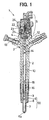
- An injector 1 according to a first embodiment is described with reference to Figs. 1,2A and 2B.
- the injector 1 is inserted to and mounted on an engine head of an engine (not shown) and injects high pressure fuel supplied from a common rail (not shown) directly to each inside of cylinders of the engine.
- the injector 1 is composed mainly of a nozzle 50, a nozzle holder 2, a control piston 3, an orifice plate 4 and an electromagnetic valve 5.
- the nozzle 50 is composed of a nozzle body 6 provided at a leading end thereof with an injection hole 6a, a needle 7 disposed slidably and reciprocatingly in the nozzle body 6 and a retaining nut 8 with which the nozzle body is connected to a lower part of the nozzle holder 2.
- the nozzle holder 2 is provided with a fuel introduction passage 10 through which high pressure fuel supplied from the common rail (high pressure source) is introduced to a fuel passage 9 formed inside the nozzle body 6, a fuel supply passage 11 through which the high pressure fuel from the common rail is supplied to a pressure control chamber 11 (also refer to Fig. 2A) and a fuel ejecting passage 13 through which the fuel from the control pressure chamber 11 is ejected to a low pressure source.
- a fuel introduction passage 10 through which high pressure fuel supplied from the common rail (high pressure source) is introduced to a fuel passage 9 formed inside the nozzle body 6, a fuel supply passage 11 through which the high pressure fuel from the common rail is supplied to a pressure control chamber 11 (also refer to Fig. 2A) and a fuel ejecting passage 13 through which the fuel from the control pressure chamber 11 is ejected to a low pressure source.
- the control piston 3 is slidably housed in a cylinder 14 formed inside the nozzle holder 2.
- the control piston 3 is connected to the needle 7 via a pressure pin 15 slidably accommodated in a cylinder 14 formed inside the nozzle holder 2.
- the orifice plate 4 is arranged at an axial end of the nozzle holder 2 to which an upper end of the cylinder 14, which constitutes the pressure control chamber 11, is opened.
- the orifice plate 4 is provided at an axial end with a part of the pressure control chamber 11 being opened to and communicating with the cylinder 14, a fuel flow-in passage 60 communicating with the fuel supply passage 12 of the nozzle holder 2, and a fuel flow-out passage 70 capable to communicate via the electromagnetic valve 5 with the fuel ejecting passage 13.
- An inner wall of the part of the pressure control chamber 11 is at least partly a conical shape inner wall whose diameter is larger toward the axial end surface of the orifice plate 4.
- the fuel flow-out passage 70 extends so as to penetrate the orifice plate 4 axially from the inner wall of the part of the pressure control chamber 11 to another axial end surface of the orifice plate 11.
- the fuel flow-out passage 70 is provided at an upper part thereof with an exit orifice 20.
- the fuel flow-in passage 60 is composed of a first passage 19 extending from the axial end surface of the orifice plate 4 and a second passage 17 extending from the inner wall of the part of the pressure control chamber 11, which intersect with each other within the orifice plate 4.
- the second passage 17 is a blind passage and an entrance orifice 18 formed partly in the first passage 19 runs into the second passage 17 (blind passage).
- the entrance orifice 18 is formed by drilling from an axial end surface of the orifice plate 4.
- the second passage 17, whose diameter is axially substantially uniform, is formed as the blind passage by drilling from the inner wall of the part of the pressure control chamber 11 so that an extended axial line of the second passage 17 passes through inside of the part of the pressure control chamber 11 without running against the inner wall thereof.
- the entrance orifice 18 is connected substantially perpendicularly to the first passage 17 at a position away by more than 0.2 mm from a dead end of the first passage.
- Inner diameter (flow path diameter) of the exit orifice 20 is larger than that of the entrance orifice 18.
- the electromagnetic valve 5 is composed of an armature 21 operative to allow and interrupt a flow communication between the fuel flow-out passage 70 and the fuel ejecting passage 13 by opening and closing the exit orifice 20, a spring 21 urging the armature 21 in a valve closing direction (downward in Fig. 1), a solenoid 23 driving the armature 21 in a valve opening direction.
- the electromagnetic valve 5 is mounted via the orifice plate 4 on the axial end of the nozzle holder 2 and connected to the nozzle holder 2 by a retaining nut 24.
- Fuel is discharged from a fuel injection pump (not shown) and delivered to the common rail.
- High pressure fuel which is accumulated to given pressure in the accumulated pressure chamber of the common rail, is introduced to the fuel passage 9 of the nozzle body 6 and to the pressure control chamber 11.
- the electromagnetic valve 5 When the electromagnetic valve 5 is in a valve closing state (in a state that the armature 21 closes the exit orifice 20), high pressure of fuel introduced to the pressure control chamber acts on the needle 7 via the control piston 3 and the pressure pin 15 and, in corporation with a biasing force of the spring 16, urges the needle 7 in a valve closing direction.
- High pressure of fuel introduced in the fuel passage 9 acts on a pressure receiving surface of the needle 7 and urges the needle 7 in a valve opening direction.
- a force of urging the needle 7 in a valve closing direction is greater than that in a valve opening direction so that the needle 7 does not lift, thereby the injection hole 6a being closed not to inject fuel.
- the solenoid 23 When the solenoid 23 is energized and the electromagnetic valve is in a valve opening state (in a state that the armature 21 opens the exit orifice 20), the fuel communication between the fuel flow-out passage 70 and the fuel ejecting passage 13 is allowed so that the fuel in the pressure control chamber 11 is ejected via the fuel ejecting passage 13 to the low pressure source. Even if the electromagnetic valve 5 is in a valve opening state, high pressure fuel continues to be supplied to the pressure control chamber 11. However, the fuel pressure of the pressure control chamber 11 acting on the control piston 3 is reduced.
- the force of urging the needle 7 in a valve closing direction based on a sum of the fuel pressure of the pressure control chamber 11 and the biasing force of the spring 16 is reduced and, when the force of urging the needle 7 in a valve opening direction exceeds that in a valve closing direction, the needle 7 starts lifting so that the injection hole 6a is opened to inject fuel.
- injection behaviors such as injection amount and injection timing are controlled by changing the fuel pressure of the pressure control chamber 11. Therefore, it is required to accurately control so as to stabilize the fuel pressure of the pressure control chamber 11 for securing stable fuel injection. It is inevitable for this purpose to stabilize a flow of fuel in the second passage 17 after the fuel passes through the fuel flow-in passage 60, in particular, in case that the entrance orifice 18 runs into the second passage 17.
- Fig. 4 shows a test result showing every injection cycle variation 2 ⁇ of injection amount, when the distance L is changed under conditions that fuel pressure is 160 MPa and width of drive pulse is 1.01 ms. According to this test result, it is proved that stabilization of every fuel injection largely depends on the distance L and, at the distance L ⁇ 0.2 mm, every injection amount variation is relatively small. It can be concluded that, when the entrance orifice 18 is connected perpendicularly to the blind passage 17 whose inner diameter is axially uniform, the distance L ⁇ 0.2 mm serves to reduce the every injection amount variation of the fuel injection valve 1.
- the entrance orifice 18 and the exit orifice 20 are formed in a single piece of the orifice plate 4, an axial length of the orifice plate 4 is longer, compared with the conventional orifice plate made of two pieces, so that the orifice plate 4 has a sufficient space for securing an adequate length of the entrance orifice 18, whereby enhancing freedom on designing the entrance orifice 18 in such a manner that an angle of the first passage 19 to the axial end surface of the orifice plate 4 and an angle of the second passage 17 to the axial end surface of the orifice plate 4 are adequately adjusted.
- the orifice plate 4 according to the first embodiment may be modified to an orifice plate 4 according to a second embodiment, as shown in Fig. 5.
- the orifice plate 4 according to the second embodiment is different from the orifice plate 4 according to the first embodiment in a point that the fuel flow-in passage 60 is composed of a first passage 38, which is a blind passage 38, extending from the axial end surface of the orifice plate 4 and a second passage 37, which is an entrance orifice 37, extending from the inner wall of the part of the pressure control chamber 11, which intersect with each other within the orifice plate 4.
- the first passage 38 is formed by drilling from an axial end surface of the orifice plate 4.
- the entrance orifice 37 is formed by drilling from the inner wall of the part of the pressure control chamber 11 so that an extended axial line of the second passage 17 passes through inside of the part of the pressure control chamber 11 without running against the inner wall thereof .
- an axial length of the orifice plate 4 is longer, compared with the conventional orifice plate made of two pieces, so that the orifice plate 4 has a sufficient space for securing an adequate length of the entrance orifice 37, whereby enhancing freedom on designing the entrance orifice 37 in such a manner that an angle ⁇ 1 of the first passage (blind passage) 38 to the axial end surface of the orifice plate 4, as shown in Figs. 6A and 6B, and an angle of the second passage (entrance orifice) 37 to the axial end surface of the orifice plate 4, as shown in Figs. 7A and 7B, are adequately adjusted.
- the angle ⁇ 1 of the first passage (blind passage) 38 to the axial end surface of the orifice plate 4 falls within a range from 25° to 90° and the angle ⁇ 2 of the second passage (entrance orifice) 37 to the axial end surface of the orifice plate 4 falls within a range from 15° to 55°.
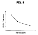
- an amount of fuel passing through the entrance orifice 37 is variable according to a variation of a length of the entrance orifice 37 and the length of the entrance orifice 37 can be enlarged by changing the angle ⁇ 1 or ⁇ 2 of the first or second passages 38 or 37 from a state shown in Fig. 6A or 7B to that shown in Fig. 6B or 7A. Accordingly, it is very easy to slightly change the flow amount of fuel passing through the entrance orifice 37 in order to secure accurate and stable fuel injection.
Landscapes
- Engineering & Computer Science (AREA)
- Chemical & Material Sciences (AREA)
- Combustion & Propulsion (AREA)
- Mechanical Engineering (AREA)
- General Engineering & Computer Science (AREA)
- Physics & Mathematics (AREA)
- Fluid Mechanics (AREA)
- Manufacturing & Machinery (AREA)
- Fuel-Injection Apparatus (AREA)
Applications Claiming Priority (4)
| Application Number | Priority Date | Filing Date | Title |
|---|---|---|---|
| JP2001286934A JP3882555B2 (ja) | 2001-09-20 | 2001-09-20 | 燃料噴射弁 |
| JP2001286934 | 2001-09-20 | ||
| JP2001367031A JP3882597B2 (ja) | 2001-11-30 | 2001-11-30 | 燃料噴射弁 |
| JP2001367031 | 2001-11-30 |
Publications (3)
| Publication Number | Publication Date |
|---|---|
| EP1296055A2 true EP1296055A2 (de) | 2003-03-26 |
| EP1296055A3 EP1296055A3 (de) | 2004-12-01 |
| EP1296055B1 EP1296055B1 (de) | 2006-01-11 |
Family
ID=26622591
Family Applications (1)
| Application Number | Title | Priority Date | Filing Date |
|---|---|---|---|
| EP02020960A Expired - Lifetime EP1296055B1 (de) | 2001-09-20 | 2002-09-19 | Brennstoffeinspritzventil mit drosselnder Lochplatte |
Country Status (4)
| Country | Link |
|---|---|
| US (1) | US6698666B2 (de) |
| EP (1) | EP1296055B1 (de) |
| CN (1) | CN1208548C (de) |
| DE (1) | DE60208615T2 (de) |
Cited By (4)
| Publication number | Priority date | Publication date | Assignee | Title |
|---|---|---|---|---|
| CN102400823A (zh) * | 2011-11-09 | 2012-04-04 | 王晓燕 | 一种电控柴油机喷油器 |
| WO2015078629A1 (de) * | 2013-11-28 | 2015-06-04 | Robert Bosch Gmbh | Kraftstoffinjektor |
| WO2016005180A1 (en) * | 2014-07-08 | 2016-01-14 | Delphi International Operations Luxembourg S.À R.L. | Fuel injector for an internal combustion engine |
| WO2016020469A1 (de) * | 2014-08-08 | 2016-02-11 | Continental Automotive Gmbh | Drosseleinrichtung zum steuern einer einer kraftstoff-einspritzdüse zuzuführenden kraftstoffmenge sowie einspritzeinrichtung |
Families Citing this family (10)
| Publication number | Priority date | Publication date | Assignee | Title |
|---|---|---|---|---|
| JP4062221B2 (ja) * | 2003-09-17 | 2008-03-19 | 株式会社デンソー | 電磁アクチュエータ、電磁アクチュエータの製造方法、および燃料噴射弁 |
| JP4066959B2 (ja) * | 2004-01-27 | 2008-03-26 | 株式会社デンソー | 燃料噴射装置 |
| JP2005226580A (ja) * | 2004-02-13 | 2005-08-25 | Denso Corp | 燃料噴射装置 |
| JP4301047B2 (ja) * | 2004-03-18 | 2009-07-22 | 株式会社デンソー | コイル装置、コイル装置の製造方法、および燃料噴射弁 |
| JP2006090176A (ja) * | 2004-09-22 | 2006-04-06 | Denso Corp | インジェクタ |
| DE102007038139A1 (de) * | 2007-08-13 | 2009-02-19 | Robert Bosch Gmbh | Elektrischer Stecker mit Kraftstoffrücklauf |
| JP5169669B2 (ja) * | 2007-11-02 | 2013-03-27 | 株式会社デンソー | 燃圧検出装置、及び燃圧検出システム |
| JP5262933B2 (ja) * | 2009-04-03 | 2013-08-14 | 株式会社デンソー | 燃料噴射装置 |
| EP2570650B1 (de) * | 2010-05-12 | 2015-06-24 | Toyota Jidosha Kabushiki Kaisha | Kraftstoffeinspritzventil |
| JP5195890B2 (ja) * | 2010-12-21 | 2013-05-15 | トヨタ自動車株式会社 | 燃料噴射弁および内燃機関 |
Family Cites Families (8)
| Publication number | Priority date | Publication date | Assignee | Title |
|---|---|---|---|---|
| FR2145081A5 (de) * | 1971-07-08 | 1973-02-16 | Peugeot & Renault | |
| US4129256A (en) * | 1977-09-12 | 1978-12-12 | General Motors Corporation | Electromagnetic unit fuel injector |
| ES2025054B3 (es) * | 1985-12-02 | 1992-03-16 | Marco Alfredo Ganser | Aparato para inyeccion de fuel para motores de combustion interna. |
| CH689282A5 (de) * | 1994-03-29 | 1999-01-29 | Christian Dipl-Ing Eth Mathis | Einspritzventil fuer eine insbesondere als Dieselmotor vorgesehene Brennkraftmaschine. |
| US6027037A (en) | 1995-12-05 | 2000-02-22 | Denso Corporation | Accumulator fuel injection apparatus for internal combustion engine |
| GB9810208D0 (en) * | 1998-05-13 | 1998-07-08 | Lucas Ind Plc | Fuel injector |
| JP3557996B2 (ja) * | 1999-06-21 | 2004-08-25 | トヨタ自動車株式会社 | 燃料噴射装置 |
| DE19936668A1 (de) * | 1999-08-04 | 2001-02-22 | Bosch Gmbh Robert | Common-Rail-Injektor |
-
2002
- 2002-09-19 US US10/246,638 patent/US6698666B2/en not_active Expired - Lifetime
- 2002-09-19 DE DE60208615T patent/DE60208615T2/de not_active Expired - Lifetime
- 2002-09-19 EP EP02020960A patent/EP1296055B1/de not_active Expired - Lifetime
- 2002-09-20 CN CN02142470.5A patent/CN1208548C/zh not_active Expired - Fee Related
Cited By (8)
| Publication number | Priority date | Publication date | Assignee | Title |
|---|---|---|---|---|
| CN102400823A (zh) * | 2011-11-09 | 2012-04-04 | 王晓燕 | 一种电控柴油机喷油器 |
| WO2015078629A1 (de) * | 2013-11-28 | 2015-06-04 | Robert Bosch Gmbh | Kraftstoffinjektor |
| WO2016005180A1 (en) * | 2014-07-08 | 2016-01-14 | Delphi International Operations Luxembourg S.À R.L. | Fuel injector for an internal combustion engine |
| US10047709B2 (en) | 2014-07-08 | 2018-08-14 | Delphi Technologies Ip Limited | Fuel injector for an internal combustion engine |
| WO2016020469A1 (de) * | 2014-08-08 | 2016-02-11 | Continental Automotive Gmbh | Drosseleinrichtung zum steuern einer einer kraftstoff-einspritzdüse zuzuführenden kraftstoffmenge sowie einspritzeinrichtung |
| CN106662056A (zh) * | 2014-08-08 | 2017-05-10 | 大陆汽车有限公司 | 用于控制待供给至燃料喷嘴的燃料的量的节流装置以及喷射装置 |
| US10240566B2 (en) | 2014-08-08 | 2019-03-26 | Continental Automotive Gmbh | Throttle device for controlling an amount of fuel to be supplied to a fuel injection nozzle, as well as an injection device |
| CN106662056B (zh) * | 2014-08-08 | 2020-03-27 | 大陆汽车有限公司 | 控制待供给至燃料喷嘴的燃料量的节流装置以及喷射装置 |
Also Published As
| Publication number | Publication date |
|---|---|
| US20030052202A1 (en) | 2003-03-20 |
| US6698666B2 (en) | 2004-03-02 |
| CN1405446A (zh) | 2003-03-26 |
| CN1208548C (zh) | 2005-06-29 |
| EP1296055A3 (de) | 2004-12-01 |
| EP1296055B1 (de) | 2006-01-11 |
| DE60208615D1 (de) | 2006-04-06 |
| DE60208615T2 (de) | 2006-09-14 |
Similar Documents
| Publication | Publication Date | Title |
|---|---|---|
| JP3700981B2 (ja) | 蓄圧式燃料噴射装置 | |
| EP1296055B1 (de) | Brennstoffeinspritzventil mit drosselnder Lochplatte | |
| US6820858B2 (en) | Electromagnetic valve for controlling an injection valve of an internal combustion engine | |
| US6994273B2 (en) | Fuel injection valve for internal combustion engines | |
| JPS6045750B2 (ja) | 空気圧縮噴射式内燃機関用ポンプ‐ノズル装置 | |
| JP4418594B2 (ja) | 着座ピンアクチュエータを備える油圧作動燃料噴射器 | |
| EP1163440B1 (de) | Kraftstoffinjektor | |
| US7172140B2 (en) | Fuel injection valve for internal combustion engines with damping chamber reducing pressure oscillations | |
| CZ20031313A3 (cs) | Vstřikovací tryska pro spalovací motory | |
| KR100730866B1 (ko) | 연료 분사 밸브 | |
| US6276335B1 (en) | Fuel injection valve | |
| JP2007239735A (ja) | 燃料噴射ノズル、燃料噴射装置、およびインジェクタ | |
| JPH07324665A (ja) | 噴射量決定を行う間隙通路をチェックするための案内付き燃料噴射ノズル | |
| JP3882555B2 (ja) | 燃料噴射弁 | |
| JP4103583B2 (ja) | ノズル及び燃料インジェクタ及び内燃機関 | |
| EP0974750A2 (de) | Brennstoffeinspritzpumpe mit Speicher zur Dampfverhinderung | |
| JP3882597B2 (ja) | 燃料噴射弁 | |
| US6913212B2 (en) | Oil activated fuel injector control with delay plunger | |
| US6526943B2 (en) | Control valve for hydraulically oil activated fuel injector | |
| JP3844092B2 (ja) | 蓄圧式燃料噴射装置 | |
| JP3818206B2 (ja) | 燃料噴射弁 | |
| US6923382B2 (en) | Hydraulically actuated injector with delay piston and method of using the same | |
| KR100213567B1 (ko) | 엔진의 가변 인젝션 시스템 | |
| US20020073969A1 (en) | Rail connection with rate shaping behavior for a hydraulically actuated fuel injector | |
| US20230077533A1 (en) | Injection nozzle for injecting fuel under high pressure |
Legal Events
| Date | Code | Title | Description |
|---|---|---|---|
| PUAI | Public reference made under article 153(3) epc to a published international application that has entered the european phase |
Free format text: ORIGINAL CODE: 0009012 |
|
| AK | Designated contracting states |
Kind code of ref document: A2 Designated state(s): AT BE BG CH CY CZ DE DK EE ES FI FR GB GR IE IT LI LU MC NL PT SE SK TR Designated state(s): AT BE BG CH CY CZ DE DK EE ES FI FR GB GR IE IT LI LU MC NL PT SE SK TR |
|
| AX | Request for extension of the european patent |
Extension state: AL LT LV MK RO SI |
|
| PUAL | Search report despatched |
Free format text: ORIGINAL CODE: 0009013 |
|
| AK | Designated contracting states |
Kind code of ref document: A3 Designated state(s): AT BE BG CH CY CZ DE DK EE ES FI FR GB GR IE IT LI LU MC NL PT SE SK TR |
|
| AX | Request for extension of the european patent |
Extension state: AL LT LV MK RO SI |
|
| 17P | Request for examination filed |
Effective date: 20050428 |
|
| GRAP | Despatch of communication of intention to grant a patent |
Free format text: ORIGINAL CODE: EPIDOSNIGR1 |
|
| AKX | Designation fees paid |
Designated state(s): DE FR IT |
|
| GRAS | Grant fee paid |
Free format text: ORIGINAL CODE: EPIDOSNIGR3 |
|
| GRAA | (expected) grant |
Free format text: ORIGINAL CODE: 0009210 |
|
| AK | Designated contracting states |
Kind code of ref document: B1 Designated state(s): DE FR IT |
|
| REF | Corresponds to: |
Ref document number: 60208615 Country of ref document: DE Date of ref document: 20060406 Kind code of ref document: P |
|
| ET | Fr: translation filed | ||
| PLBE | No opposition filed within time limit |
Free format text: ORIGINAL CODE: 0009261 |
|
| STAA | Information on the status of an ep patent application or granted ep patent |
Free format text: STATUS: NO OPPOSITION FILED WITHIN TIME LIMIT |
|
| 26N | No opposition filed |
Effective date: 20061012 |
|
| PGFP | Annual fee paid to national office [announced via postgrant information from national office to epo] |
Ref country code: IT Payment date: 20140925 Year of fee payment: 13 |
|
| REG | Reference to a national code |
Ref country code: FR Ref legal event code: PLFP Year of fee payment: 14 |
|
| PGFP | Annual fee paid to national office [announced via postgrant information from national office to epo] |
Ref country code: FR Payment date: 20150626 Year of fee payment: 14 |
|
| PG25 | Lapsed in a contracting state [announced via postgrant information from national office to epo] |
Ref country code: IT Free format text: LAPSE BECAUSE OF NON-PAYMENT OF DUE FEES Effective date: 20150919 |
|
| REG | Reference to a national code |
Ref country code: FR Ref legal event code: ST Effective date: 20170531 |
|
| PG25 | Lapsed in a contracting state [announced via postgrant information from national office to epo] |
Ref country code: FR Free format text: LAPSE BECAUSE OF NON-PAYMENT OF DUE FEES Effective date: 20160930 |
|
| PGFP | Annual fee paid to national office [announced via postgrant information from national office to epo] |
Ref country code: DE Payment date: 20200925 Year of fee payment: 19 |
|
| REG | Reference to a national code |
Ref country code: DE Ref legal event code: R119 Ref document number: 60208615 Country of ref document: DE |
|
| PG25 | Lapsed in a contracting state [announced via postgrant information from national office to epo] |
Ref country code: DE Free format text: LAPSE BECAUSE OF NON-PAYMENT OF DUE FEES Effective date: 20220401 |