EP1296101A2 - Wärmetauscheranordnung für eine Heizeinrichtung, insbesondere eine Kraftfahrzeugheizeinrichtung - Google Patents
Wärmetauscheranordnung für eine Heizeinrichtung, insbesondere eine Kraftfahrzeugheizeinrichtung Download PDFInfo
- Publication number
- EP1296101A2 EP1296101A2 EP02015117A EP02015117A EP1296101A2 EP 1296101 A2 EP1296101 A2 EP 1296101A2 EP 02015117 A EP02015117 A EP 02015117A EP 02015117 A EP02015117 A EP 02015117A EP 1296101 A2 EP1296101 A2 EP 1296101A2
- Authority
- EP
- European Patent Office
- Prior art keywords
- heat exchanger
- projection
- wall
- area
- housing
- Prior art date
- Legal status (The legal status is an assumption and is not a legal conclusion. Google has not performed a legal analysis and makes no representation as to the accuracy of the status listed.)
- Granted
Links
- 238000010438 heat treatment Methods 0.000 claims description 11
- 230000007704 transition Effects 0.000 claims description 4
- 239000012530 fluid Substances 0.000 claims description 3
- 239000007789 gas Substances 0.000 description 16
- 238000002485 combustion reaction Methods 0.000 description 9
- 239000007788 liquid Substances 0.000 description 2
- XLYOFNOQVPJJNP-UHFFFAOYSA-N water Substances O XLYOFNOQVPJJNP-UHFFFAOYSA-N 0.000 description 2
- 239000000567 combustion gas Substances 0.000 description 1
- 230000000694 effects Effects 0.000 description 1
- 238000007493 shaping process Methods 0.000 description 1
- 238000010792 warming Methods 0.000 description 1
Images


Classifications
-
- F—MECHANICAL ENGINEERING; LIGHTING; HEATING; WEAPONS; BLASTING
- F24—HEATING; RANGES; VENTILATING
- F24H—FLUID HEATERS, e.g. WATER OR AIR HEATERS, HAVING HEAT-GENERATING MEANS, e.g. HEAT PUMPS, IN GENERAL
- F24H1/00—Water heaters, e.g. boilers, continuous-flow heaters or water-storage heaters
- F24H1/22—Water heaters other than continuous-flow or water-storage heaters, e.g. water heaters for central heating
- F24H1/24—Water heaters other than continuous-flow or water-storage heaters, e.g. water heaters for central heating with water mantle surrounding the combustion chamber or chambers
- F24H1/26—Water heaters other than continuous-flow or water-storage heaters, e.g. water heaters for central heating with water mantle surrounding the combustion chamber or chambers the water mantle forming an integral body
- F24H1/263—Water heaters other than continuous-flow or water-storage heaters, e.g. water heaters for central heating with water mantle surrounding the combustion chamber or chambers the water mantle forming an integral body with a dry-wall combustion chamber
Definitions
- the present invention relates to a heat exchanger arrangement for a Heating device, in particular a motor vehicle heating device, comprising a pot-like housing with a bottom area and a wall area, being on a side facing the housing interior of the A floor protrusion arrangement is provided;
- DE 196 13 760 A1 discloses a heat exchanger arrangement for a Heater, wherein this heat exchanger arrangement is pot-shaped and surrounds a combustion chamber with its wall area. The one from the Hot exhaust gases emerging from the combustion chamber hit the floor area, are deflected axially there and then flow along the wall area to the axially open end of the heat exchanger housing.
- a Heat exchanger arrangement for a heating device in particular a Motor vehicle heater, comprising a pot-like housing with a Bottom area and a wall area, one of which is the interior of the housing facing side of the floor area a floor protrusion arrangement is provided.
- the floor protrusion arrangement at least one in the direction of the wall area includes extending rib-like bottom projection.
- the heat exchanger housing Due to the inventive design of the heat exchanger housing on the one hand it ensures that by increasing the surface area good heat transfer capacity by enlarging the heat transfer surface provided. Provision is essential for this at least one rib-like projection on the bottom area.
- the orientation of this rib-like projection namely in Direction away from the wall, for example approximately with radial orientation in relation to a longitudinal central axis of the housing, for the fact that in the floor area hitting the housing and there in the Generally heated gas radially outward and then axially redirected when flowing along a comparatively large surface experiences significantly lower gas flow resistance than when providing a variety of pin-like projections is the case.
- the bottom projection arrangement a plurality of has base projections arranged in a star-like configuration. Due to the star-like configuration, as already mentioned, at Enlarged overall surface for the lowest possible flow resistance taken care of. It can be provided, for example, that the Floor protrusions extend from a central area of the floor area Extend towards the wall area. To flow around the rib-like To hinder protrusions as little as possible, it is suggested that the floor protrusions are in their closer to each other End areas are not connected.
- the Bottom projections are curved, preferably opposite the swirl direction of a fluid flow flowing towards the bottom region is curved is trained. Enable by the curved design the bottom projections a better entry of the incoming fluid or the incoming gas in the space between the individual floor protrusions and thus reduce the flow resistance.
- a wall projection arrangement is provided, comprising at least one bottom projection of the bottom projection arrangement assigned one adjoining this and moving towards wall projection extending away from the floor area. Also at Flow along the wall area is thus for the heated gas an enlarged surface is provided.
- the flow resistance can already be provided in the floor area can be further reduced.
- This can be further preferred be provided that in a transition area between the Floor area and the wall area at least one floor projection merges into a wall projection essentially without interruption.
- the wall projection arrangement at least has a wall protrusion on which no base protrusion followed.
- a wall projection can then, for example, in the Be provided between two wall projections connect an assigned floor protrusion.
- the one or more wall projections can be designed such that they approximately in the direction of a longitudinal central axis of the housing extend.
- the present invention further relates to a heating device, which a Has heat exchanger assembly according to the invention.
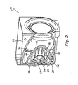
- Fig. 1 is a general view of the essential components shown with 10 heater, such as as Auxiliary heating or auxiliary heater can be used in a motor vehicle can.
- the heating device 10 includes one generally designated 12 Combustion chamber, from which a flame shield 14 is used during combustion resulting heated gases in the flame tube 16 enclosed space extending along a longitudinal axis L. 18 occur.
- the flame tube 16 is at its from the combustion chamber 12 distant end portion 20 axially open.
- An essentially pot-shaped housing 22 of a heat exchanger arrangement 24 surrounds the flame tube 16 radially on the outside and lies with its bottom region 26 the axially open end region 20 of the flame tube 16 opposite.
- One at the bottom area 26 in a connection area 28 adjoining wall area 30 of the housing 22 extends approximately parallel to the flame tube 16 and approximately also along the longitudinal axis L, which is also a longitudinal center line for the flame tube 16 and the housing 22 forms.
- annular space area 32 is formed between the flame tube 16 and the wall area 30 of the housing 22 . That from the axially open end area 20 of the flame tube 16 escaping heated gases meet the Bottom area 26 and are there, as shown in Fig. 1 by arrows, first deflected radially outwards and then in the axial direction, see above that they are along the flame tube 16 and the wall region 30 again towards the combustion chamber 14 and radially outside of it be given outside.
- Housing 22 of the heat exchanger assembly 24 on its outside surround another housing 36, commonly referred to as a water jacket is.
- a water jacket is another housing 36, commonly referred to as a water jacket.
- rib-like elevations 38 are provided, which ensure that the to warming liquid in the best possible heat transfer contact with can enter the housing 22.
- the housing 22 instructs its bottom region 26 on the inside of the housing, that is to say Flame tube 16 facing side 40 a generally designated 42 Floor protrusion arrangement on.
- the bottom projections end in their radially inner region 46 44 near the central region 48 of the base region 26 there, however, not in mutual connection. It will be close to that central area 48 is essentially enclosed by end areas 46 Space area 50 is formed, in which the central area of the flame tube 16 flowing gases can occur. At the redirection these gases then pass radially outward through the spaces 52 between two bottom projections 44 and radially outwards In this way it is ensured that at the bottom area 16 no room or shielded or blocked against flow Volume areas arise.
- an inner side 31 recognizable wall projection arrangement 54 is also provided in the figures.
- This comprises a plurality of wall projections 56, which extend along the housing 22 or the wall region 30 extend approximately in the direction of the longitudinal axis L. It can be seen that in the transition region 28 each of the bottom projections 44 merges into a wall projection 56 assigned to this, this transition is preferably designed without interruption. Furthermore, between each two wall projections 56 to which one Bottom projection 44 connects, a wall projection 56 'is provided in each case, to which no bottom projection 44 connects. One recognizes before all in the top view of FIG.
- An essential characteristic of the configuration according to the invention of the housing 22 is that at a comparatively large for heat transfer contributing inner surface the flow resistance for that Flame tube 16 leaving heated gases kept comparatively low is because of the different protrusions which increase the overall surface contribute in the direction of flow, which for the heated gases is predetermined or provided. This will the total flow resistance for those generated during combustion heated gases are kept small, which is a very efficient operation of the Heating device allowed.
- FIG. 4 shows a view of a bottom region 26 of an alternative embodiment Housing 22. It can be seen here that the bottom projections 44 are curved from radially outside to radially inside, so that in the area of radially inner free end portions 46 of these one extension directional component have in the circumferential direction. That from the combustion chamber 14 has heated gas flowing along the flame tube 16 Due to the conveying effect of a blower used, which is indicated by the arrows in Fig. 4. By the opposite configuration of the floor protrusions curved in this swirl direction 44 becomes in the axial direction and with a twist towards the bottom region 26 flowing heated gas an easier entry into between each allows two of the bottom projections 44 formed space and thus a reduction in flow resistance is achieved.
Landscapes
- Engineering & Computer Science (AREA)
- Physics & Mathematics (AREA)
- Thermal Sciences (AREA)
- Chemical & Material Sciences (AREA)
- Combustion & Propulsion (AREA)
- Mechanical Engineering (AREA)
- General Engineering & Computer Science (AREA)
- Air-Conditioning For Vehicles (AREA)
Abstract
Description
- Fig. 1
- eine Längsschnittansicht einer Heizeinrichtung, welche eine erfindungsgemäße Wärmetauscheranordnung aufweist;
- Fig. 2
- eine perspektivische Ansicht einer Heizeinrichtung, teilweise im Schnitt dargestellt;
- Fig. 3
- eine Axialansicht eines Wärmetauschergehäuses;
- Fig. 4
- eine Querschnittansicht eines Wärmetauschergehäuses nahe dem Bodenbereich desselben.
Claims (10)
- Wärmetauscheranordnung für eine Heizeinrichtung, insbesondere eine Kraftfahrzeugheizeinrichtung, umfassend ein topfartiges Gehäuse (22) mit einem Bodenbereich (26) und einem Wandungsbereich (30), wobei an einer dem Gehäuseinneren zugewandten Seite (40) des Bodenbereichs (26) eine Bodenvorsprungsanordnung (42) vorgesehen ist,
dadurch gekennzeichnet, dass die Bodenvorsprungsanordnung (42) wenigstens einen sich in Richtung von dem Wandungsbereich (30) weg erstreckenden rippenartigen Bodenvorsprung (44) umfasst. - Wärmetauscheranordnung nach Anspruch 1,
dadurch gekennzeichnet, dass die Bodenvorsprungsanordnung (42) eine Mehrzahl von in sternartiger Konfiguration angeordneten Bodenvorsprüngen (44) aufweist. - Wärmetauscheranordnung nach Anspruch 2,
dadurch gekennzeichnet, dass die Bodenvorsprünge (44) sich von einem zentralen Bereich (48) des Bodenbereichs (26) in Richtung zum Wandungsbereich (30) erstrecken. - Wärmetauscheranordnung nach Anspruch 2 oder 3,
dadurch gekennzeichnet, dass die Bodenvorsprünge (44) in ihren einander näher liegenden Endbereichen (46) nicht miteinander in Verbindung stehen. - Wärmetauscheranordnung nach einem der Ansprüche 2 bis 4,
dadurch gekennzeichnet, dass wenigstens ein Teil der Bodenvorsprünge (44) gekrümmt ausgebildet ist, vorzugsweise entgegengesetzt der Drallrichtung eines auf den Bodenbereich (26) zuströmenden Fluidstroms gekrümmt ausgebildet ist. - Wärmetauscheranordnung nach einem der Ansprüche 1 bis 5,
dadurch gekennzeichnet, dass an dem Wandungsbereich (30) an einer dem Gehäuseinneren zugewandten Seite (31) eine Wandungsvorsprungsanordnung (54) vorgesehen ist, umfassend wenigstens einem Bodenvorsprung (44) der Bodenvorsprungsanordnung (42) zugeordnet einen an diesen anschließenden und sich in Richtung vom Bodenbereich (26) weg erstreckenden Wandungsvorsprung (56). - Wärmetauscheranordnung nach Anspruch 6,
dadurch gekennzeichnet, dass in einem Übergangsbereich (28) zwischen dem Bodenbereich (26) und dem Wandungsbereich (30) wenigstens ein Bodenvorsprung (44) im Wesentlichen unterbrechungsfrei in einen Wandungsvorsprung (56) übergeht. - Wärmetauscheranordnung nach Anspruch 6 oder 7,
dadurch gekennzeichnet, dass die Wandungsvorsprungsanordnung (54) wenigstens einen Wandungsvorsprung (56') aufweist, an welchen kein Bodenvorsprung (44) anschließt. - Wärmetauscheranordnung nach einem der Ansprüche 6 bis 8,
dadurch gekennzeichnet, dass der wenigstens eine Wandungsvorsprung (56) sich näherungsweise in Richtung einer Längsmittelachse (L) des Gehäuses (22) erstreckt. - Heizeinrichtung, insbesondere für ein Kraftfahrzeug, umfassend eine Wärmetauscheranordnung (24) nach einem der vorangehenden Ansprüche.
Applications Claiming Priority (2)
| Application Number | Priority Date | Filing Date | Title |
|---|---|---|---|
| DE2001146610 DE10146610A1 (de) | 2001-09-21 | 2001-09-21 | Wärmetauscheranordnung für eine Heizeinrichtung, insbesondere eine Kraftfahrzeugheizung |
| DE10146610 | 2001-09-21 |
Publications (3)
| Publication Number | Publication Date |
|---|---|
| EP1296101A2 true EP1296101A2 (de) | 2003-03-26 |
| EP1296101A3 EP1296101A3 (de) | 2003-12-10 |
| EP1296101B1 EP1296101B1 (de) | 2012-06-20 |
Family
ID=7699827
Family Applications (1)
| Application Number | Title | Priority Date | Filing Date |
|---|---|---|---|
| EP02015117A Expired - Lifetime EP1296101B1 (de) | 2001-09-21 | 2002-07-05 | Heizeinrichtung, insbesondere eine Kraftfahrzeugheizeinrichtung |
Country Status (2)
| Country | Link |
|---|---|
| EP (1) | EP1296101B1 (de) |
| DE (1) | DE10146610A1 (de) |
Cited By (3)
| Publication number | Priority date | Publication date | Assignee | Title |
|---|---|---|---|---|
| EP1589298A3 (de) * | 2004-04-23 | 2006-09-06 | J. Eberspächer GmbH & Co. KG | Heizgerät, insbesondere für ein Fahrzeug |
| CN102642455A (zh) * | 2011-02-15 | 2012-08-22 | J.艾伯施拜谢有限责任两合公司 | 热交换装置 |
| WO2016012514A3 (de) * | 2014-07-23 | 2016-03-17 | Webasto SE | Wärmeübertrager und baukastensystem zur herstellung eines wärmeübertragers |
Families Citing this family (4)
| Publication number | Priority date | Publication date | Assignee | Title |
|---|---|---|---|---|
| DE102005053514A1 (de) | 2004-11-26 | 2006-07-06 | Webasto Ag | Luftheizgerät für ein Kraftfahrzeug |
| DE102008025314B4 (de) | 2008-05-27 | 2021-10-07 | Eberspächer Climate Control Systems GmbH | Wärmetauscheranordnung für eine Heizeinrichtung, insbesondere für ein Fahrzeug |
| DE102008034139B4 (de) | 2008-07-22 | 2022-11-10 | Eberspächer Climate Control Systems GmbH | Heizgerät, insbesondere für ein Fahrzeug |
| DE102017100133A1 (de) * | 2017-01-05 | 2018-07-05 | Eberspächer Climate Control Systems GmbH & Co. KG | Wärmetauschergehäuse |
Citations (1)
| Publication number | Priority date | Publication date | Assignee | Title |
|---|---|---|---|---|
| DE19613760A1 (de) | 1996-04-06 | 1997-10-09 | Webasto Thermosysteme Gmbh | Wärmetauscher für ein Heizgerät |
Family Cites Families (4)
| Publication number | Priority date | Publication date | Assignee | Title |
|---|---|---|---|---|
| US2744516A (en) * | 1951-10-13 | 1956-05-08 | American Air Filter Co | Portable fluid fuel burning air heater |
| FR2617579B1 (fr) * | 1987-07-03 | 1989-12-08 | Airelec Ind | Chaudiere de chauffage central pour bruleur a air souffle, comprenant un foyer sec et une resistance chauffante |
| DE3807189A1 (de) * | 1988-03-04 | 1989-09-14 | Webasto Ag Fahrzeugtechnik | Heizgeraet, insbesondere fahrzeugzusatzheizgeraet |
| DE19734814C1 (de) * | 1997-08-12 | 1999-01-14 | Webasto Thermosysteme Gmbh | Brennstoffbetriebene Heizvorrichtung mit optimierter Verbrennungsgasführung |
-
2001
- 2001-09-21 DE DE2001146610 patent/DE10146610A1/de not_active Ceased
-
2002
- 2002-07-05 EP EP02015117A patent/EP1296101B1/de not_active Expired - Lifetime
Patent Citations (1)
| Publication number | Priority date | Publication date | Assignee | Title |
|---|---|---|---|---|
| DE19613760A1 (de) | 1996-04-06 | 1997-10-09 | Webasto Thermosysteme Gmbh | Wärmetauscher für ein Heizgerät |
Cited By (6)
| Publication number | Priority date | Publication date | Assignee | Title |
|---|---|---|---|---|
| EP1589298A3 (de) * | 2004-04-23 | 2006-09-06 | J. Eberspächer GmbH & Co. KG | Heizgerät, insbesondere für ein Fahrzeug |
| CN102642455A (zh) * | 2011-02-15 | 2012-08-22 | J.艾伯施拜谢有限责任两合公司 | 热交换装置 |
| EP2489534A1 (de) * | 2011-02-15 | 2012-08-22 | J. Eberspächer GmbH & Co. KG | Wärmetauscheranordnung, insbesondere für ein brennstoffbetriebenes Fahrzeugheizgerät |
| CN102642455B (zh) * | 2011-02-15 | 2016-01-20 | J.艾伯施拜谢有限责任两合公司 | 热交换装置 |
| US9482447B2 (en) | 2011-02-15 | 2016-11-01 | Eberspaecher Climate Control Systems Gmbh & Co. Kg | Heat exchanger arrangement, especially for a fuel-operated vehicle heater |
| WO2016012514A3 (de) * | 2014-07-23 | 2016-03-17 | Webasto SE | Wärmeübertrager und baukastensystem zur herstellung eines wärmeübertragers |
Also Published As
| Publication number | Publication date |
|---|---|
| EP1296101A3 (de) | 2003-12-10 |
| EP1296101B1 (de) | 2012-06-20 |
| DE10146610A1 (de) | 2003-04-24 |
Similar Documents
| Publication | Publication Date | Title |
|---|---|---|
| DE3941049C2 (de) | ||
| DE60015374T2 (de) | Spiralwärmetauscher | |
| EP2546573B1 (de) | Fahrzeugheizgerät | |
| EP0544853B1 (de) | Luftheizgerät | |
| DE69733698T2 (de) | Einführ- und wärmeaustausch-vorrichtung für fliessfähige medien | |
| EP3301378A1 (de) | Wärmeübertragerrohr und heizkessel mit einem solchen wärmeübertragerrohr | |
| DE19734814C1 (de) | Brennstoffbetriebene Heizvorrichtung mit optimierter Verbrennungsgasführung | |
| EP1296101A2 (de) | Wärmetauscheranordnung für eine Heizeinrichtung, insbesondere eine Kraftfahrzeugheizeinrichtung | |
| DE19707647A1 (de) | Scheibenkühler | |
| EP2096372A2 (de) | Heizgerät | |
| EP1445552B1 (de) | Fahrzeugheizeinrichtung | |
| DE3320903C2 (de) | ||
| DE1293792B (de) | Vorrichtung zur Nachverbrennung des Abgases von Brennkraftmaschinen | |
| EP2157382A2 (de) | Heizgerät | |
| DE10126359B4 (de) | Kolben für einen Verbrennungsmotor | |
| EP2306112B1 (de) | Heizgerät | |
| DE19926264B4 (de) | Heizgerät | |
| DE102005001662A1 (de) | Wärmetauscherkörper und Fahrzeugheizgerät mit einem Wärmetauscherkörper | |
| DE1501777C3 (de) | Verbrennungskammer für Heizvorrichtungen, insbesondere für Lufterhitzer | |
| DE102006001590A1 (de) | Heizkessel | |
| DE102004008358B4 (de) | Fahrzeugheizgerät | |
| DE10014104B4 (de) | Brenner | |
| DE102008025314B4 (de) | Wärmetauscheranordnung für eine Heizeinrichtung, insbesondere für ein Fahrzeug | |
| DE3940299C2 (de) | ||
| DE3428829A1 (de) | Oel/gas-heizkessel |
Legal Events
| Date | Code | Title | Description |
|---|---|---|---|
| PUAI | Public reference made under article 153(3) epc to a published international application that has entered the european phase |
Free format text: ORIGINAL CODE: 0009012 |
|
| AK | Designated contracting states |
Designated state(s): AT BE BG CH CY CZ DE DK EE ES FI FR GB GR IE IT LI LU MC NL PT SE SK TR Kind code of ref document: A2 Designated state(s): AT BE BG CH CY CZ DE DK EE ES FI FR GB GR IE IT LI LU MC NL PT SE SK TR |
|
| AX | Request for extension of the european patent |
Extension state: AL LT LV MK RO SI |
|
| PUAL | Search report despatched |
Free format text: ORIGINAL CODE: 0009013 |
|
| AK | Designated contracting states |
Kind code of ref document: A3 Designated state(s): AT BE BG CH CY CZ DE DK EE ES FI FR GB GR IE IT LI LU MC NL PT SE SK TR |
|
| AX | Request for extension of the european patent |
Extension state: AL LT LV MK RO SI |
|
| RIC1 | Information provided on ipc code assigned before grant |
Ipc: 7F 24H 9/00 B Ipc: 7F 24H 1/26 A |
|
| 17P | Request for examination filed |
Effective date: 20040212 |
|
| AKX | Designation fees paid |
Designated state(s): CZ DE |
|
| 17Q | First examination report despatched |
Effective date: 20051017 |
|
| RTI1 | Title (correction) |
Free format text: HEATER, ESPECIALLY FOR A VEHICLE HEATER |
|
| GRAP | Despatch of communication of intention to grant a patent |
Free format text: ORIGINAL CODE: EPIDOSNIGR1 |
|
| GRAS | Grant fee paid |
Free format text: ORIGINAL CODE: EPIDOSNIGR3 |
|
| GRAA | (expected) grant |
Free format text: ORIGINAL CODE: 0009210 |
|
| AK | Designated contracting states |
Kind code of ref document: B1 Designated state(s): CZ DE |
|
| REG | Reference to a national code |
Ref country code: DE Ref legal event code: R096 Ref document number: 50215512 Country of ref document: DE Effective date: 20120816 |
|
| REG | Reference to a national code |
Ref country code: DE Ref legal event code: R097 Ref document number: 50215512 Country of ref document: DE |
|
| PLBE | No opposition filed within time limit |
Free format text: ORIGINAL CODE: 0009261 |
|
| STAA | Information on the status of an ep patent application or granted ep patent |
Free format text: STATUS: NO OPPOSITION FILED WITHIN TIME LIMIT |
|
| 26N | No opposition filed |
Effective date: 20130321 |
|
| REG | Reference to a national code |
Ref country code: DE Ref legal event code: R082 Ref document number: 50215512 Country of ref document: DE Representative=s name: WEICKMANN & WEICKMANN, DE |
|
| REG | Reference to a national code |
Ref country code: DE Ref legal event code: R097 Ref document number: 50215512 Country of ref document: DE Effective date: 20130321 |
|
| REG | Reference to a national code |
Ref country code: DE Ref legal event code: R081 Ref document number: 50215512 Country of ref document: DE Owner name: EBERSPAECHER CLIMATE CONTROL SYSTEMS GMBH & CO, DE Free format text: FORMER OWNER: J. EBERSPAECHER GMBH & CO. KG, 73730 ESSLINGEN, DE Effective date: 20130607 Ref country code: DE Ref legal event code: R081 Ref document number: 50215512 Country of ref document: DE Owner name: EBERSPAECHER CLIMATE CONTROL SYSTEMS GMBH & CO, DE Free format text: FORMER OWNER: J. EBERSPAECHER GMBH & CO. KG, 73730 ESSLINGEN, DE Effective date: 20120621 Ref country code: DE Ref legal event code: R082 Ref document number: 50215512 Country of ref document: DE Representative=s name: WEICKMANN & WEICKMANN, DE Effective date: 20130607 Ref country code: DE Ref legal event code: R082 Ref document number: 50215512 Country of ref document: DE Representative=s name: PATENTANWAELTE WEICKMANN & WEICKMANN, DE Effective date: 20130607 Ref country code: DE Ref legal event code: R082 Ref document number: 50215512 Country of ref document: DE Representative=s name: RUTTENSPERGER LACHNIT TROSSIN GOMOLL PATENT- U, DE Effective date: 20130607 Ref country code: DE Ref legal event code: R082 Ref document number: 50215512 Country of ref document: DE Representative=s name: RUTTENSPERGER LACHNIT TROSSIN GOMOLL, PATENT- , DE Effective date: 20130607 |
|
| PGFP | Annual fee paid to national office [announced via postgrant information from national office to epo] |
Ref country code: CZ Payment date: 20140624 Year of fee payment: 13 |
|
| REG | Reference to a national code |
Ref country code: DE Ref legal event code: R082 Ref document number: 50215512 Country of ref document: DE Representative=s name: RUTTENSPERGER LACHNIT TROSSIN GOMOLL PATENT- U, DE Ref country code: DE Ref legal event code: R082 Ref document number: 50215512 Country of ref document: DE Representative=s name: RUTTENSPERGER LACHNIT TROSSIN GOMOLL, PATENT- , DE |
|
| PGFP | Annual fee paid to national office [announced via postgrant information from national office to epo] |
Ref country code: DE Payment date: 20150731 Year of fee payment: 14 |
|
| PG25 | Lapsed in a contracting state [announced via postgrant information from national office to epo] |
Ref country code: CZ Free format text: LAPSE BECAUSE OF NON-PAYMENT OF DUE FEES Effective date: 20150705 |
|
| REG | Reference to a national code |
Ref country code: DE Ref legal event code: R119 Ref document number: 50215512 Country of ref document: DE |
|
| PG25 | Lapsed in a contracting state [announced via postgrant information from national office to epo] |
Ref country code: DE Free format text: LAPSE BECAUSE OF NON-PAYMENT OF DUE FEES Effective date: 20170201 |