EP1296101B1 - Chaudière, en particulier pour systèmes de chauffage de véhicules automobiles - Google Patents
Chaudière, en particulier pour systèmes de chauffage de véhicules automobiles Download PDFInfo
- Publication number
- EP1296101B1 EP1296101B1 EP02015117A EP02015117A EP1296101B1 EP 1296101 B1 EP1296101 B1 EP 1296101B1 EP 02015117 A EP02015117 A EP 02015117A EP 02015117 A EP02015117 A EP 02015117A EP 1296101 B1 EP1296101 B1 EP 1296101B1
- Authority
- EP
- European Patent Office
- Prior art keywords
- area
- wall
- protrusion
- heating device
- housing
- Prior art date
- Legal status (The legal status is an assumption and is not a legal conclusion. Google has not performed a legal analysis and makes no representation as to the accuracy of the status listed.)
- Expired - Lifetime
Links
- 239000007789 gas Substances 0.000 claims description 21
- 238000002485 combustion reaction Methods 0.000 claims description 17
- 238000010438 heat treatment Methods 0.000 claims description 16
- 230000007704 transition Effects 0.000 claims description 4
- 239000007788 liquid Substances 0.000 description 2
- XLYOFNOQVPJJNP-UHFFFAOYSA-N water Substances O XLYOFNOQVPJJNP-UHFFFAOYSA-N 0.000 description 2
- 239000012530 fluid Substances 0.000 description 1
Images

Classifications
-
- F—MECHANICAL ENGINEERING; LIGHTING; HEATING; WEAPONS; BLASTING
- F24—HEATING; RANGES; VENTILATING
- F24H—FLUID HEATERS, e.g. WATER OR AIR HEATERS, HAVING HEAT-GENERATING MEANS, e.g. HEAT PUMPS, IN GENERAL
- F24H1/00—Water heaters, e.g. boilers, continuous-flow heaters or water-storage heaters
- F24H1/22—Water heaters other than continuous-flow or water-storage heaters, e.g. water heaters for central heating
- F24H1/24—Water heaters other than continuous-flow or water-storage heaters, e.g. water heaters for central heating with water mantle surrounding the combustion chamber or chambers
- F24H1/26—Water heaters other than continuous-flow or water-storage heaters, e.g. water heaters for central heating with water mantle surrounding the combustion chamber or chambers the water mantle forming an integral body
- F24H1/263—Water heaters other than continuous-flow or water-storage heaters, e.g. water heaters for central heating with water mantle surrounding the combustion chamber or chambers the water mantle forming an integral body with a dry-wall combustion chamber
Definitions
- the present invention relates to a heating device, in particular a motor vehicle heating device, according to the preamble of claim 1.
- the DE 196 13 760 A1 discloses a heat exchanger assembly for a heater, said heat exchanger assembly is pot-shaped and surrounds with its wall region a combustion chamber. The exiting from the combustion chamber hot exhaust gases hit the bottom area where they are deflected axially and then flow along the Wandungs Schemes to the axially open end of the heat exchanger housing.
- this has a plurality of pin-like projections in the bottom region on the side facing the housing interior. These pin-like projections extend parallel to the longitudinal axis of the housing and have a frustoconical shape.
- the hot gas emerging from the combustion chamber flows through the spatial region formed between the pin-like projections and thereby encounters a comparatively large surface area.
- a heater is out of the DE 38 07 189 A1 known.
- this known heating device extending heat transfer ribs are provided in the wall region of a pot-like heat exchanger housing in the longitudinal direction, which extend along the outside of a flame tube.
- the flame tube is open at its end near the bottom in the direction of the bottom area.
- the bottom region is essentially planar and thus lies opposite the open end of the flame tube with a planar surface.
- the FR 2 617 579 A discloses a heating device in which deflecting ribs are present in an annular flow space. These also continue in a bottom region of the flow space, wherein the deflection ribs present in this bottom region are oriented in such a way that they guide the flowing medium in the direction of an outlet opening.
- a heater according to the preamble of claim 1 is known from DE 197 34 814 C1 known.
- the design of a heating device according to the invention ensures that by increasing the surface, a good heat transfer capability is provided by enlarging the heat transfer surface.
- Essential for this is the provision of rib-like projections on the floor area.
- the orientation of these rib-like projections namely in the direction away from the wall, ensures that the heated gas impinging on the housing in the bottom region and generally radially outward and then axially deflected there when flowing along a comparatively large surface has a significantly lower gas flow resistance learns than is the case when providing a plurality of pin-like projections.
- the bottom projection arrangement has a plurality of bottom projections arranged in a star-like configuration. Due to the star-like configuration, as already explained, the smallest possible flow resistance is provided with an increased total surface area. In this case, it may be provided, for example, that the floor projections project from a central area of the floor area Extending direction to the wall area. In order to impede the flow around the rib-like projections as little as possible, it is proposed that the bottom projections are not connected to each other in their end regions lying closer to one another.
- the bottom projections are formed curved opposite to the twisting direction of a combustion exhaust gas stream flowing to the bottom region. Due to the curved configuration, the bottom projections allow a better entry of the inflowing fluid or the inflowing gas into the space between the individual bottom projections and thus reduce the flow resistance.
- a wall projection arrangement to be provided on the wall region on a side facing the housing interior, comprising at least one bottom projection of the bottom projection arrangement associated with a wall projection which adjoins the latter and extends away from the bottom region. Even when flowing along the wall region, an enlarged surface is thus provided for the heated gas.
- By connecting to an already provided in the bottom area bottom projection of the flow resistance can be further reduced.
- it can further preferably be provided that, in a transition region between the bottom region and the wall region, at least one bottom projection merges into a wall projection essentially without interruption.
- the wall projection arrangement has at least one wall projection, to which no floor projection adjoins.
- Such a wall projection can then be provided, for example, in the region between two wall projections, which adjoin a respective associated bottom projection.
- the wall projection (s) may be configured to extend approximately in the direction of a longitudinal central axis of the housing.
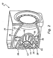
- Fig. 1 is a view of the essential components of a generally designated 10 heating device, as it can be used for example as a heater or heater in a motor vehicle application.
- the heater 10 includes a generally designated 12 Combustion chamber, from which via a flame diaphragm 14, the heated gases formed during combustion enter the space region 18 enclosed by a fire tube 16 and extending along a longitudinal axis L.
- the flame tube 16 is axially open at its end remote from the combustion chamber 12 end portion 20.
- a substantially cup-shaped housing 22 of a heat exchanger assembly 24 surrounds the flame tube 16 radially outward and lies with its bottom portion 26 of the axially open end portion 20 of the flame tube 16 opposite.
- An adjoining the bottom portion 26 in a connecting portion 28 wall portion 30 of the housing 22 extends approximately parallel to the flame tube 16 and approximately along the longitudinal axis L, which also forms a longitudinal center line for the flame tube 16 and the housing 22 simultaneously.
- an approximately ring-like space portion 32 is formed between the flame tube 16 and the wall portion 30 of the housing 22, an approximately ring-like space portion 32 is formed.
- the heated gases discharged from the axially open end region 20 of the flame tube 16 impinge on the bottom region 26 and become there as in FIG Fig. 1 represented by arrows, initially radially outward and then deflected in the axial direction, so that they are discharged along the flame tube 16 and the wall portion 30 back toward the combustion chamber 14 and radially outwardly thereof to the outside.
- the housing 22 of the heat exchanger assembly 24 is surrounded on its outer side by a generally designated as a water jacket further housing 36.
- a plurality of rib-like elevations 38 are provided on the outside of the housing 22, which ensure that the liquid to be heated can enter the housing 22 in as good a heat transfer contact as possible.
- the housing 22 at its bottom portion 26 on the interior of the housing, so also to the flame tube 16 side facing side 40 a generally designated 42 Bodenvorsprungsan extract.
- This comprises a plurality of approximately radially extending bottom projections 44 with respect to the longitudinal axis L.
- the bottom projections 44 end near the central region 48 of the bottom region 26, but are not in mutual communication there.
- a space region 50 essentially enclosed by the end regions 46 is formed, into which the gases flowing in the central region of the flame tube 16 can enter.
- these gases then pass radially through the intermediate spaces 52 between two bottom projections 44 and care is taken in this way that no space or volume regions which are shielded against flow around the bottom area are formed at the bottom region 16.
- a wall projection arrangement 54 which is also recognizable in the figures, is provided on an inner side 31.
- This comprises a plurality of wall projections 56, which extend along the housing 22 or the wall portion 30 thereof approximately in the direction of the longitudinal axis L. It can be seen that, in the transition region 28, each of the bottom projections 44 merges into a respective wall projection 56 assigned to it, wherein this transition is preferably formed without interruption. Furthermore, between each two wall projections 56, to which a bottom projection 44 connects, in each case a wall projection 56 'is provided, to which no bottom projection 44 adjoins.
- An essential characteristic of the housing 22 is that, with a comparatively large inner surface contributing to the heat transfer, the flow resistance for the heated gases leaving the flame tube 16 is kept comparatively low, since the various projections which contribute to the increase in the total surface area, in the flow direction which is responsible for the heated gases is predetermined or provided extend. Thereby, the total flow resistance for the heated gases generated in the combustion is kept small, which allows a very efficient operation of the heater.
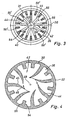
- the Fig. 4 shows a view of a bottom portion 26 of a designed according to the principles of the invention housing 22. It can be seen that the bottom projections 44 are curved from radially outward to radially inward, so that in the region of the radially inner free end portions 46 of which have an extension direction component in the circumferential direction , The heated gas flowing out of the combustion chamber 14 along the flame tube 16, due to the conveying action of an inserted blower, has a twist which is indicated by the arrows in FIG Fig. 4 is indicated.
- the bottom projections 44 By the configuration of the bottom projections 44, which is bent in the opposite direction to this twisting direction, the heated gas to be flowed in the axial direction and with swirl on the bottom region 26 is made easier to enter into the intermediate space formed between each two of the bottom projections 44, thus achieving a reduction of the flow resistance.
- the bottom projections 44 essentially form guide surfaces for the oncoming and deflected gas with their convexly curved surface regions 45.
- the statement that at least a portion of the bottom projections 44 means curved is formed so that they have curved or possibly also angled extending surface areas.
Landscapes
- Engineering & Computer Science (AREA)
- Physics & Mathematics (AREA)
- Thermal Sciences (AREA)
- Chemical & Material Sciences (AREA)
- Combustion & Propulsion (AREA)
- Mechanical Engineering (AREA)
- General Engineering & Computer Science (AREA)
- Air-Conditioning For Vehicles (AREA)
Claims (7)
- Un dispositif de chauffage, en particulier pour un véhicule, comprenant un arrangement d'échangeur de chaleur (24), ce dernier comprenant un boîtier de type pot (22) avec une section de fond (26) et une section de paroi (30), le dispositif de chauffage comprenant en outre une chambre de combustion (12) et un tube de flamme (16) menant des gaz d'échappement de combustion de la chambre de combustion (12) envers la section de fond (26), ce dernier étant à son bout en face de sa section de fond (26) ouvert axialement envers la section de fond (26), un espace annulaire ramenant des gaz d'échappement de combustion détournés dans la section de fond envers la chambre de combustion (12) étant formé entre le tube de flamme (16) et la section de paroi (30),
un arrangement de projecture de fond (42) étant prévu à un côté (40) de la section de fond (26) tourné vers l'intérieur du boîtier, l'arrangement de projecture de fond (42) comprenant une pluralité de projections de fond (44) de type renfort s'éloignant de la section de paroi (30) et arrangées dans la forme d'une étoile, caractérisé par les projections de fond étant formées courbées de radialement extérieur à radialement intérieur à l'opposé de la direction de torsion d'un flux de gaz d'échappement de combustion s'écoulant envers la section de fond (26). - Un dispositif de chauffage selon la revendication 1,
caractérisé par les projections de fond (44) s'étendant d'une section centrale (48) de la section de fond (26) envers la section de paroi (30). - Un dispositif de chauffage selon la revendication 1 ou 2,
caractérisé par les projections de fond (44) ne pas étant connectées à leurs section terminales (46) qui se rapprochent. - Un dispositif de chauffage selon une des revendications 1 à 3,
caractérisé en ce que dans la section de paroi (30) à un côté (31) orienté envers l'intérieur du boîtier un arrangement de projecture de paroi (54) est prévu, comprenant une projection de paroi (56) associé à au moins une projection de fond (44) de l'arrangement de projecture de fond (42), se raccordant à celle-là et s'éloignant de la section de fond (26). - Un dispositif de chauffage selon la revendication 4,
caractérisé par au moins une projection de fond (44) se changeant, substantiellement sans interruption, en une projection de paroi (56) dans une zone de transition (28) entre la section de fond (26) et la section de paroi (30). - Un dispositif de chauffage selon la revendication 4 ou 5,
caractérisé par l'arrangement de projecture de paroi (54) comprenant au moins une projection de paroi (56') à laquelle ne se raccorde aucune projection de fond (44). - Un dispositif de chauffage selon une des revendications 4 à 6,
caractérisé par la au moins une projection de paroi (56) s'étendant approximativement dans la direction d'une axe central longitudinal (L) du boîtier (22).
Applications Claiming Priority (2)
| Application Number | Priority Date | Filing Date | Title |
|---|---|---|---|
| DE2001146610 DE10146610A1 (de) | 2001-09-21 | 2001-09-21 | Wärmetauscheranordnung für eine Heizeinrichtung, insbesondere eine Kraftfahrzeugheizung |
| DE10146610 | 2001-09-21 |
Publications (3)
| Publication Number | Publication Date |
|---|---|
| EP1296101A2 EP1296101A2 (fr) | 2003-03-26 |
| EP1296101A3 EP1296101A3 (fr) | 2003-12-10 |
| EP1296101B1 true EP1296101B1 (fr) | 2012-06-20 |
Family
ID=7699827
Family Applications (1)
| Application Number | Title | Priority Date | Filing Date |
|---|---|---|---|
| EP02015117A Expired - Lifetime EP1296101B1 (fr) | 2001-09-21 | 2002-07-05 | Chaudière, en particulier pour systèmes de chauffage de véhicules automobiles |
Country Status (2)
| Country | Link |
|---|---|
| EP (1) | EP1296101B1 (fr) |
| DE (1) | DE10146610A1 (fr) |
Families Citing this family (7)
| Publication number | Priority date | Publication date | Assignee | Title |
|---|---|---|---|---|
| DE102004019870A1 (de) * | 2004-04-23 | 2005-11-17 | J. Eberspächer GmbH & Co. KG | Heizgerät, insbesondere für ein Fahrzeug |
| DE102005053514A1 (de) | 2004-11-26 | 2006-07-06 | Webasto Ag | Luftheizgerät für ein Kraftfahrzeug |
| DE102008025314B4 (de) | 2008-05-27 | 2021-10-07 | Eberspächer Climate Control Systems GmbH | Wärmetauscheranordnung für eine Heizeinrichtung, insbesondere für ein Fahrzeug |
| DE102008034139B4 (de) | 2008-07-22 | 2022-11-10 | Eberspächer Climate Control Systems GmbH | Heizgerät, insbesondere für ein Fahrzeug |
| DE102011004159A1 (de) | 2011-02-15 | 2012-08-16 | J. Eberspächer GmbH & Co. KG | Wärmetauscheranordnung, insbesondere für ein brennstoffbetriebenes Fahrzeugheizgerät |
| DE102014010891A1 (de) * | 2014-07-23 | 2016-01-28 | Webasto SE | Wärmeübertrager und Baukastensystem zur Herstellung eines Wärmeübertragers |
| DE102017100133A1 (de) * | 2017-01-05 | 2018-07-05 | Eberspächer Climate Control Systems GmbH & Co. KG | Wärmetauschergehäuse |
Citations (2)
| Publication number | Priority date | Publication date | Assignee | Title |
|---|---|---|---|---|
| US2744516A (en) * | 1951-10-13 | 1956-05-08 | American Air Filter Co | Portable fluid fuel burning air heater |
| DE19734814C1 (de) * | 1997-08-12 | 1999-01-14 | Webasto Thermosysteme Gmbh | Brennstoffbetriebene Heizvorrichtung mit optimierter Verbrennungsgasführung |
Family Cites Families (3)
| Publication number | Priority date | Publication date | Assignee | Title |
|---|---|---|---|---|
| FR2617579B1 (fr) * | 1987-07-03 | 1989-12-08 | Airelec Ind | Chaudiere de chauffage central pour bruleur a air souffle, comprenant un foyer sec et une resistance chauffante |
| DE3807189A1 (de) * | 1988-03-04 | 1989-09-14 | Webasto Ag Fahrzeugtechnik | Heizgeraet, insbesondere fahrzeugzusatzheizgeraet |
| DE19613760A1 (de) | 1996-04-06 | 1997-10-09 | Webasto Thermosysteme Gmbh | Wärmetauscher für ein Heizgerät |
-
2001
- 2001-09-21 DE DE2001146610 patent/DE10146610A1/de not_active Ceased
-
2002
- 2002-07-05 EP EP02015117A patent/EP1296101B1/fr not_active Expired - Lifetime
Patent Citations (2)
| Publication number | Priority date | Publication date | Assignee | Title |
|---|---|---|---|---|
| US2744516A (en) * | 1951-10-13 | 1956-05-08 | American Air Filter Co | Portable fluid fuel burning air heater |
| DE19734814C1 (de) * | 1997-08-12 | 1999-01-14 | Webasto Thermosysteme Gmbh | Brennstoffbetriebene Heizvorrichtung mit optimierter Verbrennungsgasführung |
Also Published As
| Publication number | Publication date |
|---|---|
| EP1296101A3 (fr) | 2003-12-10 |
| EP1296101A2 (fr) | 2003-03-26 |
| DE10146610A1 (de) | 2003-04-24 |
Similar Documents
| Publication | Publication Date | Title |
|---|---|---|
| EP3040638B1 (fr) | Tuyau de transfert de chaleur et chaudiere dotee d'un tel tuyau de transfert de chaleur | |
| DE60015374T2 (de) | Spiralwärmetauscher | |
| EP2546573B1 (fr) | Vehicle heating device | |
| DE10143458B4 (de) | Zusatzheizgerät mit einem Wärmeübertrager | |
| EP0544853B1 (fr) | Appareil de chauffage d'air | |
| EP0175875B1 (fr) | Brûleur à huile ou à gaz pour la génération de gaz à chaud | |
| EP1296101B1 (fr) | Chaudière, en particulier pour systèmes de chauffage de véhicules automobiles | |
| DE19734814C1 (de) | Brennstoffbetriebene Heizvorrichtung mit optimierter Verbrennungsgasführung | |
| EP2096372A2 (fr) | Appareil de chauffage | |
| WO2007079730A1 (fr) | Chaudière de chauffage | |
| EP1445552B1 (fr) | Installation de chauffage de voitures | |
| EP2157382A2 (fr) | Appareil de chauffage | |
| DE2107514A1 (de) | Vorrichtung zum Heizen mit Infrarot Strahlung | |
| DE102014214768A1 (de) | Wärmetauscheranordnung, insbesondere für ein Fahrzeugheizgerät | |
| DE102004008358B4 (de) | Fahrzeugheizgerät | |
| DE3320903C2 (fr) | ||
| EP4223398B1 (fr) | Module de mélange pour un système d'échappement d'un moteur à combustion interne | |
| EP2306112B1 (fr) | Appareil de chauffage | |
| EP1681519A2 (fr) | Echangeur de chaleur et appareil de chauffage pour véhicules avec un tel échangeur de chaleur | |
| DE19926264B4 (de) | Heizgerät | |
| DE1501777C3 (de) | Verbrennungskammer für Heizvorrichtungen, insbesondere für Lufterhitzer | |
| DE102011081401B4 (de) | Wärmetauscheranordnung, insbesondere für ein brennstoffbetriebenes Fahrzeugheizgerät | |
| EP0971194B1 (fr) | Echangeur de chaleur statique | |
| DE10262065B4 (de) | Zusatzheizgerät mit einem Wärmeübertrager | |
| DE10014104B4 (de) | Brenner |
Legal Events
| Date | Code | Title | Description |
|---|---|---|---|
| PUAI | Public reference made under article 153(3) epc to a published international application that has entered the european phase |
Free format text: ORIGINAL CODE: 0009012 |
|
| AK | Designated contracting states |
Designated state(s): AT BE BG CH CY CZ DE DK EE ES FI FR GB GR IE IT LI LU MC NL PT SE SK TR Kind code of ref document: A2 Designated state(s): AT BE BG CH CY CZ DE DK EE ES FI FR GB GR IE IT LI LU MC NL PT SE SK TR |
|
| AX | Request for extension of the european patent |
Extension state: AL LT LV MK RO SI |
|
| PUAL | Search report despatched |
Free format text: ORIGINAL CODE: 0009013 |
|
| AK | Designated contracting states |
Kind code of ref document: A3 Designated state(s): AT BE BG CH CY CZ DE DK EE ES FI FR GB GR IE IT LI LU MC NL PT SE SK TR |
|
| AX | Request for extension of the european patent |
Extension state: AL LT LV MK RO SI |
|
| RIC1 | Information provided on ipc code assigned before grant |
Ipc: 7F 24H 9/00 B Ipc: 7F 24H 1/26 A |
|
| 17P | Request for examination filed |
Effective date: 20040212 |
|
| AKX | Designation fees paid |
Designated state(s): CZ DE |
|
| 17Q | First examination report despatched |
Effective date: 20051017 |
|
| RTI1 | Title (correction) |
Free format text: HEATER, ESPECIALLY FOR A VEHICLE HEATER |
|
| GRAP | Despatch of communication of intention to grant a patent |
Free format text: ORIGINAL CODE: EPIDOSNIGR1 |
|
| GRAS | Grant fee paid |
Free format text: ORIGINAL CODE: EPIDOSNIGR3 |
|
| GRAA | (expected) grant |
Free format text: ORIGINAL CODE: 0009210 |
|
| AK | Designated contracting states |
Kind code of ref document: B1 Designated state(s): CZ DE |
|
| REG | Reference to a national code |
Ref country code: DE Ref legal event code: R096 Ref document number: 50215512 Country of ref document: DE Effective date: 20120816 |
|
| REG | Reference to a national code |
Ref country code: DE Ref legal event code: R097 Ref document number: 50215512 Country of ref document: DE |
|
| PLBE | No opposition filed within time limit |
Free format text: ORIGINAL CODE: 0009261 |
|
| STAA | Information on the status of an ep patent application or granted ep patent |
Free format text: STATUS: NO OPPOSITION FILED WITHIN TIME LIMIT |
|
| 26N | No opposition filed |
Effective date: 20130321 |
|
| REG | Reference to a national code |
Ref country code: DE Ref legal event code: R082 Ref document number: 50215512 Country of ref document: DE Representative=s name: WEICKMANN & WEICKMANN, DE |
|
| REG | Reference to a national code |
Ref country code: DE Ref legal event code: R097 Ref document number: 50215512 Country of ref document: DE Effective date: 20130321 |
|
| REG | Reference to a national code |
Ref country code: DE Ref legal event code: R081 Ref document number: 50215512 Country of ref document: DE Owner name: EBERSPAECHER CLIMATE CONTROL SYSTEMS GMBH & CO, DE Free format text: FORMER OWNER: J. EBERSPAECHER GMBH & CO. KG, 73730 ESSLINGEN, DE Effective date: 20130607 Ref country code: DE Ref legal event code: R081 Ref document number: 50215512 Country of ref document: DE Owner name: EBERSPAECHER CLIMATE CONTROL SYSTEMS GMBH & CO, DE Free format text: FORMER OWNER: J. EBERSPAECHER GMBH & CO. KG, 73730 ESSLINGEN, DE Effective date: 20120621 Ref country code: DE Ref legal event code: R082 Ref document number: 50215512 Country of ref document: DE Representative=s name: WEICKMANN & WEICKMANN, DE Effective date: 20130607 Ref country code: DE Ref legal event code: R082 Ref document number: 50215512 Country of ref document: DE Representative=s name: PATENTANWAELTE WEICKMANN & WEICKMANN, DE Effective date: 20130607 Ref country code: DE Ref legal event code: R082 Ref document number: 50215512 Country of ref document: DE Representative=s name: RUTTENSPERGER LACHNIT TROSSIN GOMOLL PATENT- U, DE Effective date: 20130607 Ref country code: DE Ref legal event code: R082 Ref document number: 50215512 Country of ref document: DE Representative=s name: RUTTENSPERGER LACHNIT TROSSIN GOMOLL, PATENT- , DE Effective date: 20130607 |
|
| PGFP | Annual fee paid to national office [announced via postgrant information from national office to epo] |
Ref country code: CZ Payment date: 20140624 Year of fee payment: 13 |
|
| REG | Reference to a national code |
Ref country code: DE Ref legal event code: R082 Ref document number: 50215512 Country of ref document: DE Representative=s name: RUTTENSPERGER LACHNIT TROSSIN GOMOLL PATENT- U, DE Ref country code: DE Ref legal event code: R082 Ref document number: 50215512 Country of ref document: DE Representative=s name: RUTTENSPERGER LACHNIT TROSSIN GOMOLL, PATENT- , DE |
|
| PGFP | Annual fee paid to national office [announced via postgrant information from national office to epo] |
Ref country code: DE Payment date: 20150731 Year of fee payment: 14 |
|
| PG25 | Lapsed in a contracting state [announced via postgrant information from national office to epo] |
Ref country code: CZ Free format text: LAPSE BECAUSE OF NON-PAYMENT OF DUE FEES Effective date: 20150705 |
|
| REG | Reference to a national code |
Ref country code: DE Ref legal event code: R119 Ref document number: 50215512 Country of ref document: DE |
|
| PG25 | Lapsed in a contracting state [announced via postgrant information from national office to epo] |
Ref country code: DE Free format text: LAPSE BECAUSE OF NON-PAYMENT OF DUE FEES Effective date: 20170201 |