EP1296123A1 - Installation transmetteur montée sur un conduit d'une installation de traítement - Google Patents
Installation transmetteur montée sur un conduit d'une installation de traítement Download PDFInfo
- Publication number
- EP1296123A1 EP1296123A1 EP01122794A EP01122794A EP1296123A1 EP 1296123 A1 EP1296123 A1 EP 1296123A1 EP 01122794 A EP01122794 A EP 01122794A EP 01122794 A EP01122794 A EP 01122794A EP 1296123 A1 EP1296123 A1 EP 1296123A1
- Authority
- EP
- European Patent Office
- Prior art keywords
- line
- measuring device
- shut
- installation according
- actuator
- Prior art date
- Legal status (The legal status is an assumption and is not a legal conclusion. Google has not performed a legal analysis and makes no representation as to the accuracy of the status listed.)
- Granted
Links
- 238000000034 method Methods 0.000 title claims abstract description 50
- 238000009434 installation Methods 0.000 title claims description 41
- 238000012360 testing method Methods 0.000 claims abstract description 58
- 238000012423 maintenance Methods 0.000 claims abstract description 21
- 230000008878 coupling Effects 0.000 claims abstract description 5
- 238000010168 coupling process Methods 0.000 claims abstract description 5
- 238000005859 coupling reaction Methods 0.000 claims abstract description 5
- 238000011010 flushing procedure Methods 0.000 claims description 24
- 239000012530 fluid Substances 0.000 claims description 2
- 238000005259 measurement Methods 0.000 abstract description 8
- 230000036316 preload Effects 0.000 description 3
- 239000000126 substance Substances 0.000 description 3
- IJGRMHOSHXDMSA-UHFFFAOYSA-N Atomic nitrogen Chemical compound N#N IJGRMHOSHXDMSA-UHFFFAOYSA-N 0.000 description 2
- 230000009194 climbing Effects 0.000 description 2
- 238000010276 construction Methods 0.000 description 2
- 238000004519 manufacturing process Methods 0.000 description 2
- 231100000331 toxic Toxicity 0.000 description 2
- 230000002588 toxic effect Effects 0.000 description 2
- 238000012549 training Methods 0.000 description 2
- 238000009530 blood pressure measurement Methods 0.000 description 1
- 230000009977 dual effect Effects 0.000 description 1
- 238000004880 explosion Methods 0.000 description 1
- 239000007789 gas Substances 0.000 description 1
- 239000011261 inert gas Substances 0.000 description 1
- 230000010354 integration Effects 0.000 description 1
- 239000007788 liquid Substances 0.000 description 1
- 229910052757 nitrogen Inorganic materials 0.000 description 1
- 238000012546 transfer Methods 0.000 description 1
- 239000002351 wastewater Substances 0.000 description 1
Images
Classifications
-
- G—PHYSICS
- G01—MEASURING; TESTING
- G01L—MEASURING FORCE, STRESS, TORQUE, WORK, MECHANICAL POWER, MECHANICAL EFFICIENCY, OR FLUID PRESSURE
- G01L27/00—Testing or calibrating of apparatus for measuring fluid pressure
- G01L27/002—Calibrating, i.e. establishing true relation between transducer output value and value to be measured, zeroing, linearising or span error determination
- G01L27/005—Apparatus for calibrating pressure sensors
Definitions
- the invention relates to a measuring device installation on a process line Process plant according to the preamble of claim 1.
- Pressure measurements In process plants such as B. in chemical and refinery plants, become Pressure measurements as field devices, preferably measuring devices installed on site Pressure transmitter used. Such pressure transmitters are, for example for measuring the process medium pressure and for recording fill levels used. Flow measurements are made in a generally known manner Measuring orifices with differential pressure transmitters are used as measuring devices.
- DE 199 21 172 C1 already provides a generic measuring device installation on a process line of a process plant known with at least a medium line between the process line and the measuring device, the measuring device being self-supporting from the at least one measuring line connected to the process line is held is.
- a shut-off device between the measuring device and the process line provided that by means of an actuator between a passage position and a shut-off position is adjustable.
- a test device can be coupled, by means of the one in the shut-off position
- Shut-off maintenance work preferably a rinse and / or a calibration that can be carried out on the measuring device.
- the meter installation is here as a pressure transmitter installation with a pressure transmitter as a measuring device, which is self-supporting from the measuring line connected to the process line is held.
- This can the measuring device installation is advantageously arranged directly on the process line and kept so that the measuring lines are stable and short can be, which on the one hand the installation effort considerably and measurement uncertainties due to long test leads can be advantageously eliminated.
- the pressure transmitter is decoupled from the process line as a measuring device.
- the shut-off device preferably a plug valve or a ball valve, by means of a handwheel as an adjusting device in a shut-off position, so that the required maintenance work on the device can now be carried out can.
- Such maintenance work regularly involves calibration and / or a rinsing of the measuring device.
- z. B a valve block provided as a connection block for a mobile test device, which is used by the worker to carry out the flushing and / or calibration work and must be connected accordingly to the connection block of the measuring device. After connecting the test device can then be carried out depending on Maintenance work a flushing and / or a calibration of the measuring device be made.
- the object of the invention is therefore to install a measuring device on a process line to create a process plant with the maintenance work on a measuring device, in particular in the case of measuring devices which are in a without Unsupported height unsupported on a process line Process plant are attached in a simple manner without much effort can be carried out with increased occupational safety.
- the test device with the measuring device is at least one Test device line can be coupled such that the test device is spaced and Can be arranged away from the measuring device and to carry out maintenance work is remotely controllable.
- the actuator of the shut-off device as Actuator formed with the shut-off device via at least one drive line can be coupled such that the actuator is spaced and Can be arranged away from the shut-off device and for adjusting the shut-off device is remotely controllable.
- the maintenance work is advantageously required cannot be carried out directly on the measuring device itself, but can conveniently and easily spaced and away from the meter from one easily accessible place, e.g. B. from the ground or from a control room become.
- This is particularly advantageous if the measuring device is in a Unsupported height unsupported on a process line a process plant is attached. Because this is the z. B. tedious and dangerous climbing a ladder with the tester avoided.
- occupational safety for the workers can thus be significantly increased, because the risk of accidents or falls when performing maintenance work on the measuring device, such as B. a calibration and / or a rinse considerably is reduced.
- the mechanical maintenance such as B.
- a rinse and / or a calibration conveniently and easily from afar z.
- B. from a control room or from the ground, can be done without the benefits of a cantilever measuring device installation attached to a process line of a process plant must be abandoned.
- the connection of the at least one test device line on the measuring device can also be done via the shut-off device take place, which in turn z.
- B. an integral part of Measuring device can be by z.
- the shut-off device as a kind of switch tap is trained.
- the actuator the shut-off device is operated electrically.
- the shut-off device according to a particularly advantageous embodiment according to claim 2 its adjustment pneumatically by means of the actuator via the drive line with compressed air as the working medium or hydraulically with a hydraulic fluid can be acted upon as a working medium.
- a working medium pressure increasing unit to which the drive line is connected. With such a working medium pressure increasing unit can be used for adjustment when actuated the required pressure generated in a particularly simple manner become.
- the working medium pressure increasing unit is preferred according to claim 4 in the case of a pneumatic actuator as an air compressor, e.g. B. as a portable pressure vessel and in the case of a hydraulic actuator as a hydraulic pump, e.g. B. designed as a portable pump.
- the shut-off device is according to claim 5 in a basic position when the actuator is not actuated in the passage position biased.
- This bias can, for example be a spring preload that is particularly simple and inexpensive at high Functional safety is to be carried out.
- the shut-off device is then activated of the actuator against the bias in the shut-off position transferable.
- shut-off device Train measurement line there are various ways in which the shut-off device Train measurement line.
- the shut-off device is preferred a ball valve or a plug valve with which a particularly good seal can be achieved in the shut-off position.
- the shut-off element also formed as a switching element be with which both the at least one test instrument line and the at least a drive line is coupled.
- a switching element be with which both the at least one test instrument line and the at least a drive line is coupled.
- the measuring device has at least one additional flushing line can be coupled with an additional rinsing device, the additional rinsing device spaced from the measuring device and can be rinsed of the measuring device and / or the at least one test device line and / or the at least one drive line can be operated remotely.
- Such a structure is particularly advantageous if via the at least one test device line a rinse to remove toxic media in the measuring device area he follows. Because then is such an additional flush line a flushing of the at least one test device line, in which if necessary residues of the toxic medium are still conceivable.
- Such an additional flushing line may also be used to flush the Drive line or support a flushing process on the measuring device respectively.
- Such an additional flushing line also provides calibration as redundancy of the measuring device using a suitable calibration medium become. As a result, the additional flushing line would also have a dual function can advantageously be used to calibrate a measuring device.
- Such an additional flushing device can be combined as a portable unit if necessary with z. B. an air compressor or a hydraulic pump as portable Be trained. Also training as a separate transportable Unity is basically possible.
- the test device line for rinsing the measuring device a flushing medium, preferably a flushing liquid or a flushing gas, z. B. an inert gas, preferably nitrogen, or for calibration of the measuring device can be loaded with a calibration medium.
- a flushing medium preferably a flushing liquid or a flushing gas, z. B. an inert gas, preferably nitrogen, or for calibration of the measuring device
- the test device line at least for rinsing the measuring device a supply line for supplying the flushing medium to the measuring device and a Drain line for the flushing medium away from the measuring device.
- the discharge line can, for example, also be returned to the test device and there in a corresponding wastewater intake room. With such a Supply line and discharge line is achieved that the contaminated Flushing medium can be removed from the measuring device in a controlled manner.
- the discharge line forms this according to claim 12 z. B. in the case of a calibration, a second feed line for the calibration medium to the measuring device.
- the discharge line if necessary also in a double function as a feed line for the calibration of the Measuring device can be used.
- the tester has a tester pressure increasing unit to which the test instrument line is connected.
- the pressure booster unit is also here preferably designed as a compressor that the previously connected advantages explained with the pressure increasing unit of the actuator having.
- connection block there is the possibility with the structure according to the invention that at least one drive line and / or the at least one test device line away from the measuring device e.g. B. down to a stationary on the floor area arranged connection block. You can use this connection block then also stationary, e.g. B. in the manner of a control room the tester and Actuator connected to the corresponding assigned lines his. With such a structure, however, there is one for each measuring device installation separate test device and a separate actuator required.
- both the test device and the actuator are designed as a mobile device that leads to a free end of the test device line or the drive line are transportable and / or mobile and can be connected accordingly to the associated free end of the respective line are.
- This can significantly increase the number of test devices and actuators can be reduced because the test devices and actuators are installed from one measuring device transported or moved to the other measuring device installation can be.
- the test device and the actuator can be according to claim 16 transported and arranged on the same mobile device be, for which purpose preferably the free ends of the tester line and the drive line adjacent to each other z. B. are arranged on the bottom.
- the Free ends can be attached to appropriate supports in a suitable Working height must be arranged.
- Both the test device and the actuator can be used in the invention be automated, d. H. that when performing Maintenance work correspondingly automated at the free ends of the least a test instrument line and the at least one drive line can be transported and / or moved. This allows such Maintenance work can also be carried out easily by unskilled workers become.
- the connections between the free ends the test instrument cable and the drive cable with the test instrument or with the Actuator can be designed in the manner of a quick coupling connection a fast and reliable connection in a generally known manner with good shut-off function.
- Such a measuring device installation is, as has already been explained in detail above particularly advantageous for such measuring devices, which are in cantilevered on a process line at a height that cannot be reached without aids are attached to a process plant. This is with the characteristics of the Claim 17 again claimed separately.
- the measuring device is preferably a pressure transmitter or a differential pressure transmitter, with which a measurement of the process medium pressure as well as the acquisition of fill levels can be carried out particularly simply and reliably is.
- the lines i.e. H. the at least one tester line and the at least one drive line either as a hose and / or Pipelines executed.
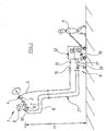
- Fig. 1 shows schematically a measuring device installation 1 on a not shown here Process management of a process plant, also not shown.
- the measuring device installation 1 comprises a measuring line 2 charged with medium between the process line, not shown here, and a pressure transmitter 3 as a measuring device, the pressure transmitter 3 being self-supporting from the the process line 2 connected to the process line.
- the pressure transmitter 3 is here in a without aids, such as z. B. a ladder unreachable height self-supporting on the process line Process plant attached.
- shut-off device 4 for example here can be designed as a plug valve or ball valve. From this shut-off device 4 is a drive line 5 down to a suitable connection height led to the bottom area 6.
- Both the lines 7, 8 of the test device line 21 and the drive line 5 are designed here, for example, as hose lines.
- the pressure transmitter is able to carry out calibration conveniently from the ground 3 first disconnect from the process line, not shown here.
- the shut-off device 4 must be brought into a shut-off position.
- a worker 11 is trained and movable as a mobile device Actuator 12, which is designed here, for example, as a pneumatic actuator is coupled to the drive line 5 via a connecting line 13, as in the schematic representation of FIG. 1 by arrow 14 only is shown extremely exemplary.
- the pneumatic actuator 15 includes an air compressor 15 of the shut-off device when the pneumatic actuator 12 is actuated 4 pressurized with compressed air via the drive line 5 and this from a passage position, not shown here, into a shut-off position transferred.
- the shut-off element is biased into the passage position as an example, which is not shown here, however, so that the transfer to the Shut-off position against this bias.
- test device 16 connected to the pressure transmitter 3 can then by appropriate actuation of the tester 16 via the lines 7, 8 of the tester line 21 a rinsing and / or calibration of the Pressure transmitter 3 conveniently made from the ground in a conventional manner become. From the lines 7, 8 of the tester line 21 z. B. the line 7 when flushing the pressure transmitter 3 as a supply line for supply the flushing medium to the pressure transmitter 3 and then the corresponding Line 8 is provided as a discharge line for the flushing medium away from the measuring device 3 become. This is also shown only very schematically Pressure increase unit 20 of the test device 16 advantageous.
- wagons can also provide all other mobile options be so B. a separately movable to the actuator 12 tester or a portable test device, which, however, is not discussed in more detail here becomes.
- the tester 16 can again from the Lines 7, 8 of the tester line 21 are simply uncoupled, which at training as a quick coupling connection is particularly easy to carry out is. Then the actuator 12 can then again in its unactuated Positioned so that the shut-off device 4 is no longer is acted upon by the compressed air.
- the shut-off device 4 can then by the previously mentioned bias in the through position, e.g. Legs Spring preload, again automatically put in the open position, so that again a connection between the measuring line and the process line can be produced.
- it can also be used without one Preload a return to the open position using the Actuator 12 can be achieved via the drive line 5 that z. B. a further parallel line is provided, which, if necessary, the provision into the passage position.
- the invention has been explained here using a pressure transmitter 3 as an example.
- a pressure transmitter 3 is of course also with a differential pressure transmitter installation possible with a parallel to the measuring line 2 further measuring line, which is not shown here, is provided.
- This too Measuring performance can be shut off via a separate shut-off device, so that in in such a case, another drive line from this shut-off device is guided down to approximately to the floor area 6 and there to the actuator can be connected.
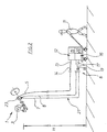
- FIG. 2 shows an alternative embodiment of a measuring device installation 22, which shows essentially the same structure as the meter installation 1 of Fig. 1.
- the shut-off device in this measuring device installation 22 Switching device 23, z. B. formed in the manner of a 3/2-way valve, with the the lines 7, 8 of the tester line 21 and the drive line 5 coupled are.
- the shut-off element 23 can be correspondingly can be moved to the shut-off position or the through position, as is well known, e.g. B. in connection with 3/2-way valves, so that this will not be discussed any further.
- a switching device 23 a particularly compact construction is possible.
Landscapes
- Chemical & Material Sciences (AREA)
- Analytical Chemistry (AREA)
- Physics & Mathematics (AREA)
- General Physics & Mathematics (AREA)
- Testing Of Devices, Machine Parts, Or Other Structures Thereof (AREA)
Priority Applications (2)
| Application Number | Priority Date | Filing Date | Title |
|---|---|---|---|
| EP20010122794 EP1296123B1 (fr) | 2001-09-21 | 2001-09-21 | Installation transmetteur montée sur un conduit d'une installation de traitement |
| DE50106641T DE50106641D1 (de) | 2001-09-21 | 2001-09-21 | Messgeräteinstallation an einer Prozessleitung einer Prozessanlage |
Applications Claiming Priority (1)
| Application Number | Priority Date | Filing Date | Title |
|---|---|---|---|
| EP20010122794 EP1296123B1 (fr) | 2001-09-21 | 2001-09-21 | Installation transmetteur montée sur un conduit d'une installation de traitement |
Publications (2)
| Publication Number | Publication Date |
|---|---|
| EP1296123A1 true EP1296123A1 (fr) | 2003-03-26 |
| EP1296123B1 EP1296123B1 (fr) | 2005-06-29 |
Family
ID=8178702
Family Applications (1)
| Application Number | Title | Priority Date | Filing Date |
|---|---|---|---|
| EP20010122794 Expired - Lifetime EP1296123B1 (fr) | 2001-09-21 | 2001-09-21 | Installation transmetteur montée sur un conduit d'une installation de traitement |
Country Status (2)
| Country | Link |
|---|---|
| EP (1) | EP1296123B1 (fr) |
| DE (1) | DE50106641D1 (fr) |
Cited By (2)
| Publication number | Priority date | Publication date | Assignee | Title |
|---|---|---|---|---|
| WO2011009475A1 (fr) * | 2009-07-24 | 2011-01-27 | Siemens Aktiengesellschaft | Dispositif d'étalonnage pour convertisseur de mesure de pression différentielle |
| WO2011009476A1 (fr) * | 2009-07-24 | 2011-01-27 | Siemens Aktiengesellschaft | Dispositif d'étalonnage pour transducteur de mesure de pression |
Citations (3)
| Publication number | Priority date | Publication date | Assignee | Title |
|---|---|---|---|---|
| US5069072A (en) * | 1990-07-26 | 1991-12-03 | Woodhead Industries, Inc. | Connector module for transducer |
| US5502659A (en) * | 1994-06-06 | 1996-03-26 | Endress+Hauser, Inc. | Method and apparatus for calibrating moisture sensors |
| DE19921172C1 (de) * | 1999-05-07 | 2000-11-16 | Martin Hess | Drucktransmitterinstallation an einer Prozeßleitung einer Prozeßanlage |
-
2001
- 2001-09-21 DE DE50106641T patent/DE50106641D1/de not_active Expired - Lifetime
- 2001-09-21 EP EP20010122794 patent/EP1296123B1/fr not_active Expired - Lifetime
Patent Citations (3)
| Publication number | Priority date | Publication date | Assignee | Title |
|---|---|---|---|---|
| US5069072A (en) * | 1990-07-26 | 1991-12-03 | Woodhead Industries, Inc. | Connector module for transducer |
| US5502659A (en) * | 1994-06-06 | 1996-03-26 | Endress+Hauser, Inc. | Method and apparatus for calibrating moisture sensors |
| DE19921172C1 (de) * | 1999-05-07 | 2000-11-16 | Martin Hess | Drucktransmitterinstallation an einer Prozeßleitung einer Prozeßanlage |
Cited By (2)
| Publication number | Priority date | Publication date | Assignee | Title |
|---|---|---|---|---|
| WO2011009475A1 (fr) * | 2009-07-24 | 2011-01-27 | Siemens Aktiengesellschaft | Dispositif d'étalonnage pour convertisseur de mesure de pression différentielle |
| WO2011009476A1 (fr) * | 2009-07-24 | 2011-01-27 | Siemens Aktiengesellschaft | Dispositif d'étalonnage pour transducteur de mesure de pression |
Also Published As
| Publication number | Publication date |
|---|---|
| DE50106641D1 (de) | 2005-08-04 |
| EP1296123B1 (fr) | 2005-06-29 |
Similar Documents
| Publication | Publication Date | Title |
|---|---|---|
| DE69116029T2 (de) | Mit Ventilen kombiniertes modulares Steuerpult | |
| EP4013636B1 (fr) | Système d'entraînement pour un collecteur de courant et procédé de montée ou d'abaissement | |
| DE102004010987A1 (de) | Sicherungseinheit | |
| DE2612562A1 (de) | Sicherheitssperrventil | |
| DE4110375A1 (de) | Verfahren und vorrichtung zum pruefen von rohrleitungen | |
| DE19541318A1 (de) | Kollisionsbeschleunigungs-Simulationsanordnung | |
| EP2180226A1 (fr) | Système de distribution de fluide modulaire | |
| EP1296123B1 (fr) | Installation transmetteur montée sur un conduit d'une installation de traitement | |
| EP3416867A1 (fr) | Bogie conçu pour un véhicule sur rails, procédé pour compenser des variations de diamètre de roues de véhicules sur rails, et véhicule sur rails | |
| DE19819716C1 (de) | Druckmittelzange | |
| DE10248319B4 (de) | Ventileinheit | |
| DE102011007826B4 (de) | Vorrichtung zur Sanierung von Rohrleitungen | |
| DE2723935C2 (de) | Vorrichtung zum Überwachen der Stellung des Stellgliedes eines hydraulischen Stellmotors | |
| EP1950354B1 (fr) | Séparateur de système | |
| DE102004059926B3 (de) | Rückschlagventil mit unterschiedlichen Flussrichtungen | |
| DE3937778C2 (de) | Alarmventilstation | |
| DE69610917T2 (de) | Abstützeinrichtung eines fahrzeugs | |
| DE4210790C2 (fr) | ||
| DE9103870U1 (de) | Vorrichtung zum Prüfen von Rohrleitungen | |
| EP3031772B1 (fr) | Dispositif de levage, en particulier pour un système d'inspection | |
| DE10348806B3 (de) | Hochdruckwasserstrahl-Anlage mit Prüfdüse | |
| DE102023003042B4 (de) | Pneumatikeinrichtung sowie Verfahren zum Betrieb einer solchen Pneumatikeinrichtung | |
| EP3587539B1 (fr) | Système d'injection et procédé de retrait d'une buse d'un tel système | |
| EP1475624B1 (fr) | Balance de calibration | |
| DE3642696A1 (de) | Rammbohrgeraet |
Legal Events
| Date | Code | Title | Description |
|---|---|---|---|
| PUAI | Public reference made under article 153(3) epc to a published international application that has entered the european phase |
Free format text: ORIGINAL CODE: 0009012 |
|
| AK | Designated contracting states |
Designated state(s): AT BE CH CY DE DK ES FI FR GB GR IE IT LI LU MC NL PT SE TR Kind code of ref document: A1 Designated state(s): AT BE CH CY DE DK ES FI FR GB GR IE IT LI LU MC NL PT SE TR |
|
| AX | Request for extension of the european patent |
Extension state: AL LT LV MK RO SI |
|
| 17P | Request for examination filed |
Effective date: 20030830 |
|
| AKX | Designation fees paid |
Designated state(s): DE FR |
|
| GRAP | Despatch of communication of intention to grant a patent |
Free format text: ORIGINAL CODE: EPIDOSNIGR1 |
|
| GRAS | Grant fee paid |
Free format text: ORIGINAL CODE: EPIDOSNIGR3 |
|
| GRAA | (expected) grant |
Free format text: ORIGINAL CODE: 0009210 |
|
| AK | Designated contracting states |
Kind code of ref document: B1 Designated state(s): DE FR |
|
| REF | Corresponds to: |
Ref document number: 50106641 Country of ref document: DE Date of ref document: 20050804 Kind code of ref document: P |
|
| PLBE | No opposition filed within time limit |
Free format text: ORIGINAL CODE: 0009261 |
|
| STAA | Information on the status of an ep patent application or granted ep patent |
Free format text: STATUS: NO OPPOSITION FILED WITHIN TIME LIMIT |
|
| 26N | No opposition filed |
Effective date: 20060330 |
|
| EN | Fr: translation not filed | ||
| PG25 | Lapsed in a contracting state [announced via postgrant information from national office to epo] |
Ref country code: FR Free format text: LAPSE BECAUSE OF FAILURE TO SUBMIT A TRANSLATION OF THE DESCRIPTION OR TO PAY THE FEE WITHIN THE PRESCRIBED TIME-LIMIT Effective date: 20060825 |
|
| PG25 | Lapsed in a contracting state [announced via postgrant information from national office to epo] |
Ref country code: FR Free format text: LAPSE BECAUSE OF FAILURE TO SUBMIT A TRANSLATION OF THE DESCRIPTION OR TO PAY THE FEE WITHIN THE PRESCRIBED TIME-LIMIT Effective date: 20050930 |
|
| PG25 | Lapsed in a contracting state [announced via postgrant information from national office to epo] |
Ref country code: FR Free format text: LAPSE BECAUSE OF FAILURE TO SUBMIT A TRANSLATION OF THE DESCRIPTION OR TO PAY THE FEE WITHIN THE PRESCRIBED TIME-LIMIT Effective date: 20050629 |
|
| PGFP | Annual fee paid to national office [announced via postgrant information from national office to epo] |
Ref country code: DE Payment date: 20110901 Year of fee payment: 11 |
|
| PG25 | Lapsed in a contracting state [announced via postgrant information from national office to epo] |
Ref country code: DE Free format text: LAPSE BECAUSE OF NON-PAYMENT OF DUE FEES Effective date: 20130403 |
|
| REG | Reference to a national code |
Ref country code: DE Ref legal event code: R119 Ref document number: 50106641 Country of ref document: DE Effective date: 20130403 |