EP1296127A2 - Dispositif pour le traitement de tissu avec vanne intégrée - Google Patents
Dispositif pour le traitement de tissu avec vanne intégrée Download PDFInfo
- Publication number
- EP1296127A2 EP1296127A2 EP02256345A EP02256345A EP1296127A2 EP 1296127 A2 EP1296127 A2 EP 1296127A2 EP 02256345 A EP02256345 A EP 02256345A EP 02256345 A EP02256345 A EP 02256345A EP 1296127 A2 EP1296127 A2 EP 1296127A2
- Authority
- EP
- European Patent Office
- Prior art keywords
- chamber
- base
- rotary member
- port
- disc
- Prior art date
- Legal status (The legal status is an assumption and is not a legal conclusion. Google has not performed a legal analysis and makes no representation as to the accuracy of the status listed.)
- Granted
Links
Images


Classifications
-
- G—PHYSICS
- G01—MEASURING; TESTING
- G01N—INVESTIGATING OR ANALYSING MATERIALS BY DETERMINING THEIR CHEMICAL OR PHYSICAL PROPERTIES
- G01N1/00—Sampling; Preparing specimens for investigation
- G01N1/28—Preparing specimens for investigation including physical details of (bio-)chemical methods covered elsewhere, e.g. G01N33/50, C12Q
- G01N1/30—Staining; Impregnating ; Fixation; Dehydration; Multistep processes for preparing samples of tissue, cell or nucleic acid material and the like for analysis
- G01N1/31—Apparatus therefor
-
- Y—GENERAL TAGGING OF NEW TECHNOLOGICAL DEVELOPMENTS; GENERAL TAGGING OF CROSS-SECTIONAL TECHNOLOGIES SPANNING OVER SEVERAL SECTIONS OF THE IPC; TECHNICAL SUBJECTS COVERED BY FORMER USPC CROSS-REFERENCE ART COLLECTIONS [XRACs] AND DIGESTS
- Y10—TECHNICAL SUBJECTS COVERED BY FORMER USPC
- Y10T—TECHNICAL SUBJECTS COVERED BY FORMER US CLASSIFICATION
- Y10T137/00—Fluid handling
- Y10T137/8593—Systems
- Y10T137/86493—Multi-way valve unit
- Y10T137/86815—Multiple inlet with single outlet
- Y10T137/86823—Rotary valve
Definitions
- THIS INVENTION relates to tissue processors for processing biological tissue, for example, for mounting on microscope slides.
- Processors of the type referred to are intended for use in subjecting tissue samples to a sequence of processing steps, involving treatment of the sample in various treatment fluids in succession. It is an object of the invention to provide a tissue processor which will facilitate such treatments.
- a tissue processor comprising a vessel having an interior chamber in communication with a valve arrangement whereby a selected one of a plurality of fluid inlets may be connected with the interior of the chamber for supply of processing fluid thereto and/or whereby the chamber may alternatively be connected with a discharge outlet, or a selected one of a plurality of discharge outlets, for discharge of fluid from the processor chamber, characterised in that the valve arrangement comprises a rotary member in sealing engagement with a valve surface fixed with respect to said chamber, said valve surface being provided with a plurality of ports connected with or providing respective said fluid inlets, and said rotary member being provided with a port selectively communicable with a said inlet and having an opening into a said chamber and communicating via a duct or passage with the last-mentioned said port.
- the processor chamber has a base in which said inlets are arranged in a ring centered on a rotary axis of said rotary member, and are selectively connectable with a single said port in an opposing part of said rotary member, the latter being formed as a disc centered on said axis and rotatable about said axis, sealing means being provided to effect a seal between the rotary member and said base around the aligned registering ports of the rotary member and said base and said axis.
- a tissue processor comprises a vessel 10 which is generally cylindrical about a vertical axis, having a generally horizontal circular base wall 12, and an upstanding cylindrical side wall 14 centred on said axis and terminating in a rim defining an opening in a top panel 16.
- a plurality of ports 20 are formed through the base wall 12, arranged in a circle centred on the central axis of the processor chamber, these ports thus being spaced apart angularly about this central axis.
- the plane of Figure 6 is selected to show one of the ports 20 in section.
- a generally flat rotary valve disc 22 which is secured to the upper end of a hollow shaft 40 extending vertically through a central axial bore through the base 12.
- the disc member 22 is preferably of corrosion resistant metal, e.g. stainless steel.
- the shaft 40 is coaxial with vessel 10 and is rotatable with respect to the vessel 10 about the central vertical axis of the vessel.
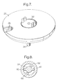
- the disc 22 has adjacent its periphery a single opening or port 26 ( Figure 4) which can be placed in communication with a respective one of the ports 20, (as shown in Figure 6), by rotating the disc 22 to the appropriate angular position, about its axis, in which said port 26 in the disc 22 is in precise and sealing registry with the respective port 20 in base 12.
- Disc 22 is secured (by means not shown) to the upper end of a hollow shaft 40 which is rotatable within a central axial bore in base 12.
- the hollow shaft 40 projects below the base 12 of the container 10, and passes through an aligned central aperture in a cover plate 31 fixed under the base 12.
- the lower end of the shaft 40 is externally screw-threaded and carries a nut 35 screw-threadedly engaged on the shaft 40.
- a washer 36 and a bearing member 38 are located around shaft 40 between nut 35 and the cover plate 31.
- a sealing ring 28 of elastomeric material carried by the disc 22 on the underside of the latter, encircles port 26 and closely engages the upper surface of the base 12 to prevent leakage of treatment fluid into the space below disc 22 via the port 26 or via a port 20 which is aligned with port 26, during supply of such fluid to the vessel 10 by way of the aligned ports 20, 26 or discharge of such fluid from the vessel by way of the aligned ports 20,26.
- the ports 20 are connected ( by means not shown) to respective reservoirs, (not shown) of respective treatment fluids, each reservoir having associated pumping means (not shown) whereby, when the port 26 is in alignment with the respective port 20, the respective fluid may be pumped from its respective reservoir to the vessel 10 or from the vessel 10 into its respective reservoir.
- Hollow shaft 40 serves principally to rotate the disc 22 and to provide a tension force producing controlled biasing of the disc 22 towards the base 12.
- the lower end of the shaft 40 may carry an encoded disc 37 co-operating with sensors (not shown) carried by members 39 carried in turn by cover plate 31, for monitoring of the rotational position of the disc 22.
- Drive for rotation of the disc 22 is applied, eg. by a geared electric motor, (not shown), to a shaft 24 which extends coaxially within shaft 40 and is rotationally supported within the shaft 40 by bearings 42 and 44.
- Shaft 24 is provided with drive features which move within corresponding features in hollow shaft 40, (see Fig. 8), such that angular agitation or oscillation of the shaft 24 about its axis can be provided over a significant arc without moving the disc 22.
- Driving shaft 24 until these drive features engage allows movement of the disc 22, (see below).
- Shaft 24 has fixed at its upper end an agitator 32 received in a central recess in the upper surface of disc 22.
- the shaft 24 and agitator 32 are rotatable in disc 22 and are sealed with respect thereto.
- the shaft 24 is further sealed with respect to shaft 40 by a seal 46 adjacent the upper end of shaft 40.
- the agitator 32 comprises a flat disc received within said central recess and prongs 33 projecting upwardly from the upper surface of said flat disc, above the upper surface of the disc 22.
- said drive features on the shaft 24 preferably comprise, at an intermediate position along the length of the shaft 24, lateral projections or teeth 60 which can engage with complementary teeth 62 provided at an intermediate position along the length of hollow shaft 40, these teeth 62 forming the corresponding features in shaft 40 referred to above.
- the teeth 62 project inwardly from the internal surface of the shaft 40.
- the shaft 24 is able to make a substantial movement about its central axis through an arc, for example 140 degrees, in the sense required to separate the last-mentioned flanks of the teeth 60 from the last mentioned flanks of the teeth 62 before the other flank of each tooth 60 engages the other flank of the other tooth 62 of shaft 40.
- each shaft 24,40 may have only one such tooth allowing oscillation through a larger arc or may have more than two equally spaced teeth allowing oscillation through only a smaller arc.
- the disc 22 may be rotated in a controlled manner via shaft 40, rotated in turn by shaft 24, to place the port 26 into communication with a selected port 20. There is sufficient distance between adjoining ports 20 to allow the port 26 and the aligned opening in the elastomeric seal 28 to be entirely occluded by the base 12 so that liquid cannot enter or leave the chamber. Thus the disc 22 need make only a small rotational movement to change from a position in which a port 20 is in full communication with the interior of the chamber and a position in which the chamber is sealed off from any such port 20.
- a rectangular-section sealing ring 30 is located in a circumferential rebate around the periphery of the disc 22 at the lower edge of the latter, the ring 30 being sealed with respect to the wall 14 of the vessel by a first O-ring accommodated in a peripheral groove in the sealing ring 30 and the sealing ring 30 being further sealed with respect to the base 12 of the vessel by a further O-ring accommodated in an annular groove in the lower end face of the sealing ring 30.
- the sealing ring 30 In operation of the apparatus, the sealing ring 30 remains stationary within the vessel and co-operates sealingly with the under-surface of the rim of the valve disc 22 and thus allows rotation of the valve disc 22 relative to the container whilst preventing passage of treatment fluid between the ring 30 and the rim of the sealing disc 22.
- the ring 30 is of PTFE or like material and provides an adequate seal with respect to the polished underside of the rim of the valve disc 22.
- the material of the ring 30 is chosen for its good wear and low friction properties.
- the elastomeric O-rings in ring 30 take up irregularities in the fit of the ring 30 with respect to the vessel 10. The friction of the O-rings with respect to the vessel wall and base and with respect to the ring 30 is sufficient to ensure that the ring 30 will remain stationery whilst the disc 22 rotates upon it.
- the fluid within the vessel may at any time be agitated or stirred to ensure circulation of the fluid around the samples contained therein, by limited rotation of the shaft 24.
- the shaft 40 may not need to be sealed with respect to base 12 because the sealing ring 30 and the port seal 28 acting between disc 22 and base 12 prevents fluid from reaching the bore in base 12 which receives shaft 40.
- the shaft 40 may be sealed with respect to the base, e.g. by means of an "O" ring (not shown) around the shaft 40.
- FIG. 3 The view which forms Figure 3 shows several openings into the processor vessel at the back of the latter, arranged in a vertical row. These are holes for an air connection, a thermistor and level sensors, (not shown).
- the fluid in the processor chamber may be heated by means of a conformal electrical heating element 41 applied to the underside of the rotary valve disc 22 and supplied with electrical current via slip-rings which may be carried on a printed circuit board 64 mounted on the underside of disc 22, these slip rings being engaged by electrical contacts or brushes 66 mounted on a plate 68 fixed to the vessel 10 and connected to a source of electrical current via conductors extending sealingly through the base 12 of vessel 10.
- a conformal electrical heating element 41 applied to the underside of the rotary valve disc 22 and supplied with electrical current via slip-rings which may be carried on a printed circuit board 64 mounted on the underside of disc 22, these slip rings being engaged by electrical contacts or brushes 66 mounted on a plate 68 fixed to the vessel 10 and connected to a source of electrical current via conductors extending sealingly through the base 12 of vessel 10.
- each treatment fluid can enter and leave the treatment chamber by its own port in the base 12 significantly reduces cross-contamination of treatment fluids.
- the vessel 10 is moulded from a chemically resistant polymer. As compared with a pressed metal vessel, this makes it possible to incorporate detailed features, such as the individual ports, with tubular extensions, etc., to a much greater degree. Furthermore, the polymer construction affords better heat insulation than a metal vessel.
Landscapes
- Health & Medical Sciences (AREA)
- Life Sciences & Earth Sciences (AREA)
- Biochemistry (AREA)
- General Health & Medical Sciences (AREA)
- Molecular Biology (AREA)
- Physics & Mathematics (AREA)
- Chemical & Material Sciences (AREA)
- Analytical Chemistry (AREA)
- Engineering & Computer Science (AREA)
- Biomedical Technology (AREA)
- General Physics & Mathematics (AREA)
- Immunology (AREA)
- Pathology (AREA)
- Sampling And Sample Adjustment (AREA)
- Centrifugal Separators (AREA)
- Surgical Instruments (AREA)
- Prostheses (AREA)
Applications Claiming Priority (2)
| Application Number | Priority Date | Filing Date | Title |
|---|---|---|---|
| GBGB0122801.4A GB0122801D0 (en) | 2001-09-21 | 2001-09-21 | Tissue projector with integrated valve |
| GB0122801 | 2001-09-21 |
Publications (3)
| Publication Number | Publication Date |
|---|---|
| EP1296127A2 true EP1296127A2 (fr) | 2003-03-26 |
| EP1296127A3 EP1296127A3 (fr) | 2005-09-07 |
| EP1296127B1 EP1296127B1 (fr) | 2008-09-03 |
Family
ID=9922482
Family Applications (1)
| Application Number | Title | Priority Date | Filing Date |
|---|---|---|---|
| EP02256345A Expired - Lifetime EP1296127B1 (fr) | 2001-09-21 | 2002-09-12 | Dispositif pour le traitement de tissu avec vanne intégrée |
Country Status (5)
| Country | Link |
|---|---|
| US (1) | US6991934B2 (fr) |
| EP (1) | EP1296127B1 (fr) |
| AT (1) | ATE407354T1 (fr) |
| DE (1) | DE60228660D1 (fr) |
| GB (1) | GB0122801D0 (fr) |
Families Citing this family (17)
| Publication number | Priority date | Publication date | Assignee | Title |
|---|---|---|---|---|
| JP3866655B2 (ja) * | 2002-12-26 | 2007-01-10 | 励起 渡辺 | 処理装置及び処理方法 |
| US7172558B2 (en) * | 2003-05-05 | 2007-02-06 | Duke University | Device for containing and analyzing surgically excised tissue and related methods |
| US9518899B2 (en) * | 2003-08-11 | 2016-12-13 | Sakura Finetek U.S.A., Inc. | Automated reagent dispensing system and method of operation |
| US7744817B2 (en) * | 2003-08-11 | 2010-06-29 | Sakura Finetek U.S.A., Inc. | Manifold assembly |
| US7767152B2 (en) * | 2003-08-11 | 2010-08-03 | Sakura Finetek U.S.A., Inc. | Reagent container and slide reaction retaining tray, and method of operation |
| US7501283B2 (en) * | 2003-08-11 | 2009-03-10 | Sakura Finetek U.S.A., Inc. | Fluid dispensing apparatus |
| US8459509B2 (en) * | 2006-05-25 | 2013-06-11 | Sakura Finetek U.S.A., Inc. | Fluid dispensing apparatus |
| CN101923018B (zh) * | 2010-09-15 | 2013-01-23 | 福州大学 | 一种利用生物组织脱水机进行脱水的方法 |
| US8752732B2 (en) | 2011-02-01 | 2014-06-17 | Sakura Finetek U.S.A., Inc. | Fluid dispensing system |
| US8932543B2 (en) | 2011-09-21 | 2015-01-13 | Sakura Finetek U.S.A., Inc. | Automated staining system and reaction chamber |
| US8580568B2 (en) | 2011-09-21 | 2013-11-12 | Sakura Finetek U.S.A., Inc. | Traceability for automated staining system |
| ES2733446T3 (es) | 2012-06-22 | 2019-11-29 | Leica Biosystems Nussloch Gmbh | Dispositivo de transporte de muestras de tejido de biopsia |
| WO2013192607A1 (fr) | 2012-06-22 | 2013-12-27 | Leica Biosystems Nussloch Gmbh | Récipient pour échantillon de tissu et procédés |
| US9097629B2 (en) | 2013-03-15 | 2015-08-04 | Leica Biosystems Nussloch Gmbh | Tissue cassette with retractable member |
| US9052256B2 (en) | 2013-03-15 | 2015-06-09 | Leica Biosystems Nussloch Gmbh | Method for processing and embedding tissue |
| CA2845832C (fr) | 2013-03-15 | 2020-09-22 | Leica Biosystems Nussloch Gmbh | Cassette de tissu a element de sollicitation |
| US11004722B2 (en) | 2017-07-20 | 2021-05-11 | Applied Materials, Inc. | Lift pin assembly |
Family Cites Families (10)
| Publication number | Priority date | Publication date | Assignee | Title |
|---|---|---|---|---|
| US2959151A (en) * | 1954-04-08 | 1960-11-08 | Ehrlich Joseph Charles | Apparatus for multiple liquid treatments of materials |
| US3238971A (en) * | 1963-04-03 | 1966-03-08 | Carmine N Cerone | Fluid distribution valve |
| FR1453945A (fr) * | 1965-07-27 | 1966-07-22 | Dispositif pour la coloration de milieux biologiques, tels qu'étalements ou frottiseffectués sur des lames de verre | |
| US3854440A (en) * | 1972-04-24 | 1974-12-17 | T Astle | Slide staining apparatus |
| US3972350A (en) * | 1975-09-24 | 1976-08-03 | Pickett John E P | Rotary valve |
| GB1536422A (en) | 1976-03-30 | 1978-12-20 | Shandon Southern Prod Ltd | Tissue processing |
| US4099483A (en) * | 1976-04-07 | 1978-07-11 | Shandon Southern Products Limited | Tissue processing apparatus |
| US4199558A (en) * | 1976-04-07 | 1980-04-22 | Shandon Southern Products Limited | Tissue processing method |
| EP0077477B1 (fr) * | 1981-10-20 | 1986-04-09 | Shandon Southern Products Limited | Appareil pour le traitement de tissus |
| GB8628371D0 (en) * | 1986-11-27 | 1986-12-31 | Shandon Southern Prod | Tissue specimen treatment apparatus |
-
2001
- 2001-09-21 GB GBGB0122801.4A patent/GB0122801D0/en not_active Ceased
-
2002
- 2002-09-12 DE DE60228660T patent/DE60228660D1/de not_active Expired - Lifetime
- 2002-09-12 AT AT02256345T patent/ATE407354T1/de not_active IP Right Cessation
- 2002-09-12 EP EP02256345A patent/EP1296127B1/fr not_active Expired - Lifetime
- 2002-09-20 US US10/251,123 patent/US6991934B2/en not_active Expired - Lifetime
Also Published As
| Publication number | Publication date |
|---|---|
| US6991934B2 (en) | 2006-01-31 |
| EP1296127B1 (fr) | 2008-09-03 |
| DE60228660D1 (de) | 2008-10-16 |
| GB0122801D0 (en) | 2001-11-14 |
| EP1296127A3 (fr) | 2005-09-07 |
| ATE407354T1 (de) | 2008-09-15 |
| US20030059928A1 (en) | 2003-03-27 |
Similar Documents
| Publication | Publication Date | Title |
|---|---|---|
| US6991934B2 (en) | Tissue processor with integrated valve | |
| RU2472413C2 (ru) | Автоматический вспениватель для молока | |
| RU2184472C2 (ru) | Устройство для механической обработки пищевых продуктов | |
| US4450758A (en) | Rotary cooking device | |
| US4792236A (en) | Multi-canister tinter with lost-motion coupling | |
| CN102361579B (zh) | 用于对食品进行蒸汽加工和搅拌的装置 | |
| KR102481826B1 (ko) | 교반장치 | |
| HK1052742A (en) | Tissue processor with integrated valve | |
| CN109589019A (zh) | 投料结构及调味机 | |
| EP0263084B1 (fr) | Friteuse pour aliments, en particulier à usage domestique | |
| GB2322271A (en) | Food stirrer for microwave oven | |
| US9907319B2 (en) | Dual-axis rotational mixer for food products | |
| US4983221A (en) | Buffing pad cleaning method and apparatus | |
| KR200142701Y1 (ko) | 묵 끓임솥 | |
| KR100778237B1 (ko) | 중금속 온라인 분석시스템 | |
| CN212394677U (zh) | 具有蒸盘结构的食物处理器 | |
| JPH08309171A (ja) | 混合攪拌装置 | |
| KR102733978B1 (ko) | 원테이크 떡반죽 가공장치 | |
| JP3634186B2 (ja) | 縦軸型シールレス撹拌機 | |
| CN1518617A (zh) | 一种改进的烧杯型印染机 | |
| WO1998006485A1 (fr) | Appareil agitateur | |
| JP7661119B2 (ja) | 加熱調理器 | |
| KR102913298B1 (ko) | 회전 조리기구 | |
| JP2007245000A (ja) | 撹拌装置 | |
| CN113558500A (zh) | 具有蒸盘结构的食物处理器 |
Legal Events
| Date | Code | Title | Description |
|---|---|---|---|
| PUAI | Public reference made under article 153(3) epc to a published international application that has entered the european phase |
Free format text: ORIGINAL CODE: 0009012 |
|
| AK | Designated contracting states |
Kind code of ref document: A2 Designated state(s): AT BE BG CH CY CZ DE DK EE ES FI FR GB GR IE IT LI LU MC NL PT SE SK TR Designated state(s): AT BE BG CH CY CZ DE DK EE ES FI FR GB GR IE IT LI LU MC NL PT SE SK TR |
|
| AX | Request for extension of the european patent |
Extension state: AL LT LV MK RO SI |
|
| PUAL | Search report despatched |
Free format text: ORIGINAL CODE: 0009013 |
|
| AK | Designated contracting states |
Kind code of ref document: A3 Designated state(s): AT BE BG CH CY CZ DE DK EE ES FI FR GB GR IE IT LI LU MC NL PT SE SK TR |
|
| AX | Request for extension of the european patent |
Extension state: AL LT LV MK RO SI |
|
| 17P | Request for examination filed |
Effective date: 20051007 |
|
| AKX | Designation fees paid |
Designated state(s): AT BE BG CH CY CZ DE DK EE ES FI FR GB GR IE IT LI LU MC NL PT SE SK TR |
|
| 17Q | First examination report despatched |
Effective date: 20071127 |
|
| GRAP | Despatch of communication of intention to grant a patent |
Free format text: ORIGINAL CODE: EPIDOSNIGR1 |
|
| GRAS | Grant fee paid |
Free format text: ORIGINAL CODE: EPIDOSNIGR3 |
|
| GRAA | (expected) grant |
Free format text: ORIGINAL CODE: 0009210 |
|
| AK | Designated contracting states |
Kind code of ref document: B1 Designated state(s): AT BE BG CH CY CZ DE DK EE ES FI FR GB GR IE IT LI LU MC NL PT SE SK TR |
|
| REG | Reference to a national code |
Ref country code: GB Ref legal event code: FG4D |
|
| REG | Reference to a national code |
Ref country code: CH Ref legal event code: EP |
|
| REG | Reference to a national code |
Ref country code: IE Ref legal event code: FG4D |
|
| REF | Corresponds to: |
Ref document number: 60228660 Country of ref document: DE Date of ref document: 20081016 Kind code of ref document: P |
|
| PG25 | Lapsed in a contracting state [announced via postgrant information from national office to epo] |
Ref country code: NL Free format text: LAPSE BECAUSE OF FAILURE TO SUBMIT A TRANSLATION OF THE DESCRIPTION OR TO PAY THE FEE WITHIN THE PRESCRIBED TIME-LIMIT Effective date: 20080903 Ref country code: ES Free format text: LAPSE BECAUSE OF FAILURE TO SUBMIT A TRANSLATION OF THE DESCRIPTION OR TO PAY THE FEE WITHIN THE PRESCRIBED TIME-LIMIT Effective date: 20081214 |
|
| PG25 | Lapsed in a contracting state [announced via postgrant information from national office to epo] |
Ref country code: FI Free format text: LAPSE BECAUSE OF FAILURE TO SUBMIT A TRANSLATION OF THE DESCRIPTION OR TO PAY THE FEE WITHIN THE PRESCRIBED TIME-LIMIT Effective date: 20080903 Ref country code: AT Free format text: LAPSE BECAUSE OF FAILURE TO SUBMIT A TRANSLATION OF THE DESCRIPTION OR TO PAY THE FEE WITHIN THE PRESCRIBED TIME-LIMIT Effective date: 20080903 |
|
| NLV1 | Nl: lapsed or annulled due to failure to fulfill the requirements of art. 29p and 29m of the patents act | ||
| PG25 | Lapsed in a contracting state [announced via postgrant information from national office to epo] |
Ref country code: BE Free format text: LAPSE BECAUSE OF FAILURE TO SUBMIT A TRANSLATION OF THE DESCRIPTION OR TO PAY THE FEE WITHIN THE PRESCRIBED TIME-LIMIT Effective date: 20080903 |
|
| PG25 | Lapsed in a contracting state [announced via postgrant information from national office to epo] |
Ref country code: MC Free format text: LAPSE BECAUSE OF NON-PAYMENT OF DUE FEES Effective date: 20080930 Ref country code: BG Free format text: LAPSE BECAUSE OF FAILURE TO SUBMIT A TRANSLATION OF THE DESCRIPTION OR TO PAY THE FEE WITHIN THE PRESCRIBED TIME-LIMIT Effective date: 20081203 |
|
| REG | Reference to a national code |
Ref country code: CH Ref legal event code: PL |
|
| PG25 | Lapsed in a contracting state [announced via postgrant information from national office to epo] |
Ref country code: PT Free format text: LAPSE BECAUSE OF FAILURE TO SUBMIT A TRANSLATION OF THE DESCRIPTION OR TO PAY THE FEE WITHIN THE PRESCRIBED TIME-LIMIT Effective date: 20090203 Ref country code: CZ Free format text: LAPSE BECAUSE OF FAILURE TO SUBMIT A TRANSLATION OF THE DESCRIPTION OR TO PAY THE FEE WITHIN THE PRESCRIBED TIME-LIMIT Effective date: 20080903 Ref country code: SK Free format text: LAPSE BECAUSE OF FAILURE TO SUBMIT A TRANSLATION OF THE DESCRIPTION OR TO PAY THE FEE WITHIN THE PRESCRIBED TIME-LIMIT Effective date: 20080903 |
|
| REG | Reference to a national code |
Ref country code: IE Ref legal event code: MM4A |
|
| PLBE | No opposition filed within time limit |
Free format text: ORIGINAL CODE: 0009261 |
|
| STAA | Information on the status of an ep patent application or granted ep patent |
Free format text: STATUS: NO OPPOSITION FILED WITHIN TIME LIMIT |
|
| PG25 | Lapsed in a contracting state [announced via postgrant information from national office to epo] |
Ref country code: IE Free format text: LAPSE BECAUSE OF NON-PAYMENT OF DUE FEES Effective date: 20080912 Ref country code: DK Free format text: LAPSE BECAUSE OF FAILURE TO SUBMIT A TRANSLATION OF THE DESCRIPTION OR TO PAY THE FEE WITHIN THE PRESCRIBED TIME-LIMIT Effective date: 20080903 Ref country code: EE Free format text: LAPSE BECAUSE OF FAILURE TO SUBMIT A TRANSLATION OF THE DESCRIPTION OR TO PAY THE FEE WITHIN THE PRESCRIBED TIME-LIMIT Effective date: 20080903 |
|
| 26N | No opposition filed |
Effective date: 20090604 |
|
| PG25 | Lapsed in a contracting state [announced via postgrant information from national office to epo] |
Ref country code: IT Free format text: LAPSE BECAUSE OF FAILURE TO SUBMIT A TRANSLATION OF THE DESCRIPTION OR TO PAY THE FEE WITHIN THE PRESCRIBED TIME-LIMIT Effective date: 20080903 |
|
| PG25 | Lapsed in a contracting state [announced via postgrant information from national office to epo] |
Ref country code: CH Free format text: LAPSE BECAUSE OF NON-PAYMENT OF DUE FEES Effective date: 20080930 Ref country code: LI Free format text: LAPSE BECAUSE OF NON-PAYMENT OF DUE FEES Effective date: 20080930 |
|
| PG25 | Lapsed in a contracting state [announced via postgrant information from national office to epo] |
Ref country code: SE Free format text: LAPSE BECAUSE OF FAILURE TO SUBMIT A TRANSLATION OF THE DESCRIPTION OR TO PAY THE FEE WITHIN THE PRESCRIBED TIME-LIMIT Effective date: 20081203 |
|
| REG | Reference to a national code |
Ref country code: HK Ref legal event code: WD Ref document number: 1052742 Country of ref document: HK |
|
| PG25 | Lapsed in a contracting state [announced via postgrant information from national office to epo] |
Ref country code: LU Free format text: LAPSE BECAUSE OF NON-PAYMENT OF DUE FEES Effective date: 20080912 Ref country code: CY Free format text: LAPSE BECAUSE OF FAILURE TO SUBMIT A TRANSLATION OF THE DESCRIPTION OR TO PAY THE FEE WITHIN THE PRESCRIBED TIME-LIMIT Effective date: 20080903 |
|
| PG25 | Lapsed in a contracting state [announced via postgrant information from national office to epo] |
Ref country code: TR Free format text: LAPSE BECAUSE OF FAILURE TO SUBMIT A TRANSLATION OF THE DESCRIPTION OR TO PAY THE FEE WITHIN THE PRESCRIBED TIME-LIMIT Effective date: 20080903 |
|
| PG25 | Lapsed in a contracting state [announced via postgrant information from national office to epo] |
Ref country code: GR Free format text: LAPSE BECAUSE OF FAILURE TO SUBMIT A TRANSLATION OF THE DESCRIPTION OR TO PAY THE FEE WITHIN THE PRESCRIBED TIME-LIMIT Effective date: 20081204 |
|
| REG | Reference to a national code |
Ref country code: FR Ref legal event code: PLFP Year of fee payment: 14 |
|
| REG | Reference to a national code |
Ref country code: FR Ref legal event code: PLFP Year of fee payment: 15 |
|
| REG | Reference to a national code |
Ref country code: FR Ref legal event code: PLFP Year of fee payment: 16 |
|
| REG | Reference to a national code |
Ref country code: FR Ref legal event code: PLFP Year of fee payment: 17 |
|
| PGFP | Annual fee paid to national office [announced via postgrant information from national office to epo] |
Ref country code: FR Payment date: 20210927 Year of fee payment: 20 |
|
| PGFP | Annual fee paid to national office [announced via postgrant information from national office to epo] |
Ref country code: GB Payment date: 20210927 Year of fee payment: 20 Ref country code: DE Payment date: 20210929 Year of fee payment: 20 |
|
| REG | Reference to a national code |
Ref country code: DE Ref legal event code: R071 Ref document number: 60228660 Country of ref document: DE |
|
| REG | Reference to a national code |
Ref country code: GB Ref legal event code: PE20 Expiry date: 20220911 |
|
| PG25 | Lapsed in a contracting state [announced via postgrant information from national office to epo] |
Ref country code: GB Free format text: LAPSE BECAUSE OF EXPIRATION OF PROTECTION Effective date: 20220911 |