EP1296131A2 - Appareil d'inspection video - Google Patents
Appareil d'inspection video Download PDFInfo
- Publication number
- EP1296131A2 EP1296131A2 EP02256165A EP02256165A EP1296131A2 EP 1296131 A2 EP1296131 A2 EP 1296131A2 EP 02256165 A EP02256165 A EP 02256165A EP 02256165 A EP02256165 A EP 02256165A EP 1296131 A2 EP1296131 A2 EP 1296131A2
- Authority
- EP
- European Patent Office
- Prior art keywords
- camera
- inspection apparatus
- cable
- camera means
- video
- Prior art date
- Legal status (The legal status is an assumption and is not a legal conclusion. Google has not performed a legal analysis and makes no representation as to the accuracy of the status listed.)
- Withdrawn
Links
- 238000007689 inspection Methods 0.000 title claims abstract description 46
- 239000011152 fibreglass Substances 0.000 claims description 3
- 238000005286 illumination Methods 0.000 claims description 3
- 238000005381 potential energy Methods 0.000 claims description 3
- 239000004033 plastic Substances 0.000 claims description 2
- 238000000034 method Methods 0.000 claims 2
- 230000001419 dependent effect Effects 0.000 claims 1
- 230000005611 electricity Effects 0.000 description 1
Images


Classifications
-
- B—PERFORMING OPERATIONS; TRANSPORTING
- B65—CONVEYING; PACKING; STORING; HANDLING THIN OR FILAMENTARY MATERIAL
- B65H—HANDLING THIN OR FILAMENTARY MATERIAL, e.g. SHEETS, WEBS, CABLES
- B65H75/00—Storing webs, tapes, or filamentary material, e.g. on reels
- B65H75/02—Cores, formers, supports, or holders for coiled, wound, or folded material, e.g. reels, spindles, bobbins, cop tubes, cans, mandrels or chucks
- B65H75/34—Cores, formers, supports, or holders for coiled, wound, or folded material, e.g. reels, spindles, bobbins, cop tubes, cans, mandrels or chucks specially adapted or mounted for storing and repeatedly paying-out and re-storing lengths of material provided for particular purposes, e.g. anchored hoses, power cables
- B65H75/38—Cores, formers, supports, or holders for coiled, wound, or folded material, e.g. reels, spindles, bobbins, cop tubes, cans, mandrels or chucks specially adapted or mounted for storing and repeatedly paying-out and re-storing lengths of material provided for particular purposes, e.g. anchored hoses, power cables involving the use of a core or former internal to, and supporting, a stored package of material
- B65H75/40—Cores, formers, supports, or holders for coiled, wound, or folded material, e.g. reels, spindles, bobbins, cop tubes, cans, mandrels or chucks specially adapted or mounted for storing and repeatedly paying-out and re-storing lengths of material provided for particular purposes, e.g. anchored hoses, power cables involving the use of a core or former internal to, and supporting, a stored package of material mobile or transportable
-
- B—PERFORMING OPERATIONS; TRANSPORTING
- B65—CONVEYING; PACKING; STORING; HANDLING THIN OR FILAMENTARY MATERIAL
- B65H—HANDLING THIN OR FILAMENTARY MATERIAL, e.g. SHEETS, WEBS, CABLES
- B65H75/00—Storing webs, tapes, or filamentary material, e.g. on reels
- B65H75/02—Cores, formers, supports, or holders for coiled, wound, or folded material, e.g. reels, spindles, bobbins, cop tubes, cans, mandrels or chucks
- B65H75/34—Cores, formers, supports, or holders for coiled, wound, or folded material, e.g. reels, spindles, bobbins, cop tubes, cans, mandrels or chucks specially adapted or mounted for storing and repeatedly paying-out and re-storing lengths of material provided for particular purposes, e.g. anchored hoses, power cables
- B65H75/38—Cores, formers, supports, or holders for coiled, wound, or folded material, e.g. reels, spindles, bobbins, cop tubes, cans, mandrels or chucks specially adapted or mounted for storing and repeatedly paying-out and re-storing lengths of material provided for particular purposes, e.g. anchored hoses, power cables involving the use of a core or former internal to, and supporting, a stored package of material
- B65H75/44—Constructional details
-
- G—PHYSICS
- G01—MEASURING; TESTING
- G01N—INVESTIGATING OR ANALYSING MATERIALS BY DETERMINING THEIR CHEMICAL OR PHYSICAL PROPERTIES
- G01N21/00—Investigating or analysing materials by the use of optical means, i.e. using sub-millimetre waves, infrared, visible or ultraviolet light
- G01N21/84—Systems specially adapted for particular applications
- G01N21/88—Investigating the presence of flaws or contamination
- G01N21/95—Investigating the presence of flaws or contamination characterised by the material or shape of the object to be examined
- G01N21/954—Inspecting the inner surface of hollow bodies, e.g. bores
-
- H—ELECTRICITY
- H04—ELECTRIC COMMUNICATION TECHNIQUE
- H04N—PICTORIAL COMMUNICATION, e.g. TELEVISION
- H04N7/00—Television systems
- H04N7/18—Closed-circuit television [CCTV] systems, i.e. systems in which the video signal is not broadcast
- H04N7/181—Closed-circuit television [CCTV] systems, i.e. systems in which the video signal is not broadcast for receiving images from a plurality of remote sources
-
- B—PERFORMING OPERATIONS; TRANSPORTING
- B65—CONVEYING; PACKING; STORING; HANDLING THIN OR FILAMENTARY MATERIAL
- B65H—HANDLING THIN OR FILAMENTARY MATERIAL, e.g. SHEETS, WEBS, CABLES
- B65H2701/00—Handled material; Storage means
- B65H2701/30—Handled filamentary material
- B65H2701/34—Handled filamentary material electric cords or electric power cables
Definitions
- the present invention relates to video inspection apparatus and in particular to video inspection apparatus for use in inspecting the interior of pipework.
- Passing through the cable are wires providing an electrical supply to the camera at the end of the cable and also feeding back the video signals obtained by the camera.
- lighting is provided along with the camera so that the interior of the pipe can be illuminated during inspection.
- the power supply for the lighting also passes along the cable.
- inspection apparatus such as described above has been used in inspection of large scale pipes such as sewers. Usually it is transported to site by a van and power for the apparatus is provided by batteries of the transporting vehicle, or by a portable generator or from a mains electricity supply.
- a cable supplying power will be run e.g. from the vehicle and will engage in a socket provided on the inspection apparatus, which will itself be manually portable to be located near an entry point for the sewer pipe to be inspected.
- a video screen showing the image recorded by the camera has in the past been mounted on the stand supporting the cable reel, but at other times the video display has been located inside the transporting vehicle and cable run from the cable reel to the video screen apparatus inside the vehicle.
- the present invention provides video inspection apparatus for inspecting a pipeline comprising; first and second cables windable respectively in first and second reels on drum means rotatably mounted on support means; and first camera means connected at one end of the first cable; second camera means connected at one end of the second cable; wherein:
- the video inspection apparatus of the prior art comprised a single reel of cable with a single camera mounted at the end.
- a single reel of cable In order to allow for inspection of different diameter pipes at least two different reels of cable would have to be transported routinely by those involved in the inspection.
- a certain diameter of camera is advantageously used to give a good image quality, this diameter of camera would not be usable in small diameter pipes, for which it is necessary to use a smaller diameter camera.
- the cameras have lighting apparatus associated therewith, usually in the form of light emitting diodes. The greater the diameter of pipe, the greater the need for illumination and the more LEDs are required, thus the greater size of the camera/lighting apparatus as a whole.
- the present invention provides a solution to this problem in that it provides in a single transportable unit two different reels of cable with two different diameter cameras. The operator can take just the single unit to any inspection and they select at the site which camera is the most appropriate. The two cameras share a single video screen and a selector switch will allow the operator to choose which camera is connected to the video screen.
- the present invention could also provide apparatus in which the first and second camera means are identical, but the first and second cables connected thereto differ.
- one cable could be short and stiff to allow for the pushing of one camera around tight corners, whilst the other cable could be long and more flexible to allow inspection of a long length of straight pipe or a length with gentle curves.
- the first and second camera means could be different to each other and the first and second cables different to each other.
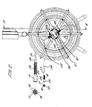
- FIG. 1 there can be seen in the figure video inspection apparatus 10 comprising a video display unit 11 mounted on a frame 12 which carries a rotatable reel 13 mounted to rotate about a spindle extending from the frame 12.
- a battery pack 14 and two different cameras 15 and 16.
- the camera 15 has a diameter of 50mm and the camera 16 has a diameter of 25mm.
- Figure 2 at the left hand side there can be seen the front of the two cameras 15 and 16.
- At the front of the camera 15 there is a lens 18 for a camera typically comprising a CMOS sensor and this is surrounded by a plurality of LEDs 19 which provide light to illuminate the interior of a pipe being inspected by the camera.
- the camera 16 has a lens 20 and the camera is surrounded by a plurality of LEDs 21, which again provide illumination in the interior of the pipe being inspected.
- the camera 15 has a head 22 which comprises the CMOS sensor and its supporting electronics and also the illuminating LEDs.
- a section 23 comprising a coiled spring surrounding the wires which provide the head 22 with power and which relay video signals from the head 22.
- the coiled spring 23 allows the head 22 to move around corners in the pipework.
- the coiled spring 23 extends between the head 22 and a socket section 24 which allows connection of the camera apparatus and associated lighting to a cable 25.
- the camera apparatus 16 comprises a head 26 which houses a CMOS sensor, illuminating LEDs and their supporting electronics.
- This head is connected to a socket section 27 by a coiled spring 28 which allows the camera head 26 to flex and move around corners within the pipework.
- the socket 27 connects the camera to a cable 29.
- the cable 25 is wound in a reel on the drum 13 which is pivotally mounted on a hub 30 of the supporting frame 12.
- the drum 13 is rotatable about the hub 30.
- the cable 29 is wound in a reel also on the drum 13.
- the reel of cable 25 and the reel of cable 29 are both concentric, having coincident axes along the axis of the hub 30.
- the reel of cable 25 is wound to have a diameter greater than the diameter of the wound reel of cable 29.
- the cable 25 terminates at the end opposite to the end connected to the camera at a plug 40 which is attached to a socket 41 mounted on the hub 42 of the rotatable drum 13.
- the cable 25 has an end 43 which has a plug 44 engageable with a socket 45 mounted on the hub 42 of the cable drum 13.
- switches 46 and 47 On the hub 42 there can be seen in Figure 2 two switches 46 and 47. These switches allow the operator to select between the two cameras 15 and 16. Operation of switch 46 allows selection of camera 16 and operation of switch 47 allows selection of camera 15.
- the switches 46 and 47 switch the cameras 15 and 16 on and off by controlling the power supply to the cameras.
- the switches 46 and 47 could be replaced by a single three-way switch.
- the video display apparatus comprises an LCD screen 50 and some controls 51, 52, 53 and 54 which allow control of the display, e.g. brightness, contrast, colour and positioning of the image on the screen.
- the video display apparatus 11 can be pivoted about the top of the stand 12 and then fixed in place by using the clamp 55.
- the video inspection apparatus 10 is completely self-contained in that it contains batteries needed to power the cameras 15 and 16 and the video display apparatus 11.
- the image obtained by either camera 15 or camera 16 is displayed by the video display unit 11 which is part of the apparatus.
- the operator can select for use either a small diameter camera 16 or a larger diameter camera 15.
- the batteries used by the apparatus will be rechargeable. Typically once charged the battery power pack would provide 3 to 4 hours of power supply and it is envisaged that this would be sufficient to last through a day of use by an operative, with the pack then being recharged overnight. Additionally or alternatively the apparatus could be supplied with several battery packs easily interchangeable.
- the drum 13 is associated with a self retracting mechanism.
- a ratchet mechanism operates so that the cable remains at its drawn out length. Once the operator has finished inspection then he will release the ratchet mechanism in a known manner and the drum 13 will rotate under the action of potential energy stored in a spring and will wind the cable 25 or 29 back onto the drum.
- the cables 25 and 29 could be manually unwound from, and then manually wound back on to the reels.
- the overall apparatus will be of a size and weight suitable for carrying by a single operator to a point of inspection.
- Each cable 25, 29 is preferably a cable comprising a fibreglass core over which a plastic jacket is extruded, the fibreglass rod providing the necessary rigidity and the jacket providing protection for the rod and preventing the rod from snapping.
- an operator will transport the apparatus to an inspection site. The operator will then select whether it is appropriate to use the small scale camera 16 or the larger scale camera 15. Once a selection has been made then the operator will pull the relevant cable 25 or 29 from the rotatable drum and feed the camera 15 or 16 along pipework to be inspected, pushing the camera 15 or 16 along manually using the relatively stiff cable 25 or 29. The operator will use the switches 46 and 47 to supply power to the chosen camera and the associated lighting apparatus. The image of the inspected pipe will then appear on the screen 50 and the operator will be able to view the interior of the pipe being inspected. It is possible that the video display apparatus 11 could incorporate some way of recording the video sequence captured by the camera, for subsequent replay.
- the apparatus Whilst above the drum 13 is shown mounted with an axis of rotation horizontal, it is possible that the apparatus could be constructed in such a way that the drum 13 rotates about a vertical axis. It is also possible that the video display apparatus 11 rather than being mounted at the top of the stand 12 is mounted on the hub of the stand. The video display apparatus could be separate and independent and linked by cable to the stand or frame.
- the cameras would be identical, but attached to cables which have different characteristics.
- One cable could be short and stiff to allow access around tight bends.
- the other cable could be longer and less stiff to allow inspection of long lengths of straight pipe or pipes with gentle corners.
- both the cameras could be different to each other and the cables different to each other.
Landscapes
- Engineering & Computer Science (AREA)
- Multimedia (AREA)
- Signal Processing (AREA)
- Physics & Mathematics (AREA)
- Health & Medical Sciences (AREA)
- Life Sciences & Earth Sciences (AREA)
- Chemical & Material Sciences (AREA)
- Analytical Chemistry (AREA)
- Biochemistry (AREA)
- General Health & Medical Sciences (AREA)
- General Physics & Mathematics (AREA)
- Immunology (AREA)
- Pathology (AREA)
- Investigating Materials By The Use Of Optical Means Adapted For Particular Applications (AREA)
- Electric Cable Installation (AREA)
Applications Claiming Priority (2)
| Application Number | Priority Date | Filing Date | Title |
|---|---|---|---|
| GB0122592 | 2001-09-19 | ||
| GB0122592A GB2380082B (en) | 2001-09-19 | 2001-09-19 | Video inspection apparatus |
Publications (2)
| Publication Number | Publication Date |
|---|---|
| EP1296131A2 true EP1296131A2 (fr) | 2003-03-26 |
| EP1296131A3 EP1296131A3 (fr) | 2003-09-17 |
Family
ID=9922342
Family Applications (1)
| Application Number | Title | Priority Date | Filing Date |
|---|---|---|---|
| EP02256165A Withdrawn EP1296131A3 (fr) | 2001-09-19 | 2002-09-05 | Appareil d'inspection video |
Country Status (5)
| Country | Link |
|---|---|
| US (1) | US20030052967A1 (fr) |
| EP (1) | EP1296131A3 (fr) |
| AU (1) | AU2002331955A1 (fr) |
| GB (2) | GB2380088B (fr) |
| WO (1) | WO2003025536A2 (fr) |
Cited By (6)
| Publication number | Priority date | Publication date | Assignee | Title |
|---|---|---|---|---|
| FR2866440A1 (fr) * | 2004-02-13 | 2005-08-19 | Coillie Olivier Van | Dispositif endoscopique pour la verification in situ de conduites d'eau, de gaz, ou similaires |
| US11248982B2 (en) | 2018-05-09 | 2022-02-15 | Milwaukee Electric Tool Corporation | Hub connection for pipeline inspection device |
| WO2023010044A1 (fr) * | 2021-07-30 | 2023-02-02 | SeeScan, Inc. | Tambour de stockage de câble avec face de tambour inclinée vers l'intérieur pour système de caméra d'inspection de tuyau |
| USD983469S1 (en) | 2019-05-09 | 2023-04-11 | Milwaukee Electric Tool Corporation | Hub for pipeline inspection device |
| US11659142B2 (en) | 2020-02-12 | 2023-05-23 | Milwaukee Electric Tool Corporation | Pipeline inspection device with enhanced image control |
| USD988113S1 (en) | 2019-05-09 | 2023-06-06 | Milwaukee Electric Tool Corporation | Receptacle for pipeline inspection device |
Families Citing this family (23)
| Publication number | Priority date | Publication date | Assignee | Title |
|---|---|---|---|---|
| GB0515993D0 (en) * | 2005-08-03 | 2005-09-07 | Super Rod Ltd | Inspection tool |
| US20070132842A1 (en) * | 2005-12-09 | 2007-06-14 | Bellsouth Intellectual Property Corporation | Video systems for hazardous material environment |
| AU2006203774B2 (en) * | 2006-08-30 | 2013-09-26 | Olex Australia Pty Limited | Pipe inspection robot |
| US20080073495A1 (en) * | 2006-09-22 | 2008-03-27 | Washington Savannah River Co., Llc | Portable remote camera and radiation monitor |
| US8547428B1 (en) * | 2006-11-02 | 2013-10-01 | SeeScan, Inc. | Pipe mapping system |
| US8395661B1 (en) * | 2009-02-16 | 2013-03-12 | Seektech, Inc. | Pipe inspection system with selective image capture |
| US20100033986A1 (en) * | 2008-08-05 | 2010-02-11 | Perceptron Inc. | Light Pipe For Imaging Head of Video Inspection Device |
| US10009582B2 (en) * | 2009-02-13 | 2018-06-26 | Seesoon, Inc. | Pipe inspection system with replaceable cable storage drum |
| US20110108654A1 (en) * | 2009-11-11 | 2011-05-12 | Emerson Electric Co. | Reel frames for remote video inspection systems |
| US10371305B1 (en) * | 2012-02-22 | 2019-08-06 | SeeScan, Inc. | Dockable tripodal camera control unit |
| NO342734B1 (no) * | 2012-11-01 | 2018-08-06 | Vision Io As | Sensordeksel for en rørinspeksjonskonstruksjon |
| WO2014182737A1 (fr) * | 2013-05-07 | 2014-11-13 | SeeScan, Inc. | Ensemble ressorts pour inspection de canalisation avec câble de poussée |
| EP3038965B1 (fr) | 2013-08-26 | 2020-08-05 | SeeScan, Inc. | Système d'inspection vidéo comportant un appareil d'amarrage d'unité de contrôle de caméra mobile |
| US9395216B2 (en) * | 2013-10-22 | 2016-07-19 | The United States Of America, As Represented By The Secretary Of The Army | Disappearing controllable-arch sensor boom or crane |
| WO2016014697A1 (fr) * | 2014-07-22 | 2016-01-28 | Clearwater Downstream Services, LLC | Système et procédé d'inspection simultanée multi-tube de système à faisceau de tubes verticaux |
| EP3555704B1 (fr) | 2016-12-15 | 2024-04-17 | Milwaukee Electric Tool Corporation | Dispositif d'inspection de canalisation |
| GB201709915D0 (en) * | 2017-06-21 | 2017-08-02 | Nixon Jordan | Cable management assembly |
| CN108840179B (zh) * | 2018-05-11 | 2020-06-05 | 中国煤炭科工集团太原研究院有限公司 | 一种视频遥控用电缆与胶管同步式收放缆滚筒 |
| CN111208146B (zh) * | 2018-11-22 | 2023-05-16 | 北京世纪东方智汇科技股份有限公司 | 一种隧道线缆检测系统及检测方法 |
| CN209673136U (zh) * | 2019-05-07 | 2019-11-22 | 深圳市华普森电子有限公司 | 高清智能一体化管道探测器 |
| US11946600B1 (en) * | 2023-10-11 | 2024-04-02 | Shenzhen Sanyi Technology Co., Ltd. | Pipeline detection device |
| USD1120070S1 (en) * | 2024-01-17 | 2026-03-24 | Shenzhen Woshijie Electronic Technology Co., Ltd. | Pipe detector |
| US12352705B1 (en) * | 2025-01-10 | 2025-07-08 | Shenzhen Sanyi Technology Co., Ltd. | Pipeline endoscopic mechanism |
Family Cites Families (12)
| Publication number | Priority date | Publication date | Assignee | Title |
|---|---|---|---|---|
| US4561558A (en) * | 1984-10-15 | 1985-12-31 | The Babcock & Wilcox Company | Vent cover |
| US4651558A (en) * | 1985-09-13 | 1987-03-24 | Cues, Inc. | Method and apparatus for inspecting lateral lines |
| US5090259A (en) * | 1988-01-18 | 1992-02-25 | Olympus Optical Co., Ltd. | Pipe-inspecting apparatus having a self propelled unit |
| GB2242497B (en) * | 1990-03-31 | 1992-08-12 | Stc Plc | Pipe inspection system |
| DE4220900A1 (de) * | 1992-06-25 | 1994-01-05 | Deutsche Aerospace | Vorrichtung zur Prüfung von Hohlräumen |
| US5467640A (en) * | 1994-05-02 | 1995-11-21 | Salinas; Joe E. | Pipeline testing and leak locating apparatus and method |
| US5655727A (en) * | 1995-05-18 | 1997-08-12 | Meurer Research, Inc. | Sludge collector method and drive with shared reel for taking up and paying out cables |
| DE29604682U1 (de) * | 1996-03-14 | 1997-08-14 | itv Gesellschaft für Industrie-TV mbH, 87488 Betzigau | Vorrichtung für die Inspektion von Rohrleitungen |
| US5754220A (en) * | 1996-04-26 | 1998-05-19 | Emerson Electric Company | Apparatus for inspecting the interior of pipes |
| DE19654065B4 (de) * | 1996-12-23 | 2005-10-13 | itv Gesellschaft für Industrie-TV mbH | Gerät für die optische Inspektion von Rohrleitungen |
| US5992247A (en) * | 1998-04-23 | 1999-11-30 | Aries Industries Incorporated | Apparatus for inspecting lateral sewer pipes |
| DE19934527C2 (de) * | 1999-07-22 | 2002-02-28 | Rothenberger Werkzeuge Ag | Geräteeinheit für die Inspektion von Hohlräumen mit einer Video-Kamera |
-
2001
- 2001-09-19 GB GB0220368A patent/GB2380088B/en not_active Expired - Fee Related
- 2001-09-19 GB GB0122592A patent/GB2380082B/en not_active Expired - Fee Related
-
2002
- 2002-09-05 EP EP02256165A patent/EP1296131A3/fr not_active Withdrawn
- 2002-09-19 WO PCT/GB2002/004247 patent/WO2003025536A2/fr not_active Ceased
- 2002-09-19 US US10/246,626 patent/US20030052967A1/en not_active Abandoned
- 2002-09-19 AU AU2002331955A patent/AU2002331955A1/en not_active Abandoned
Cited By (12)
| Publication number | Priority date | Publication date | Assignee | Title |
|---|---|---|---|---|
| FR2866440A1 (fr) * | 2004-02-13 | 2005-08-19 | Coillie Olivier Van | Dispositif endoscopique pour la verification in situ de conduites d'eau, de gaz, ou similaires |
| WO2005088381A1 (fr) * | 2004-02-13 | 2005-09-22 | Entreprise Artisanale Van Coillie | Dispositif endoscopique pour la verification in situ de conduites d’eau, de gaz ou similaires |
| US11248982B2 (en) | 2018-05-09 | 2022-02-15 | Milwaukee Electric Tool Corporation | Hub connection for pipeline inspection device |
| US11892373B2 (en) | 2018-05-09 | 2024-02-06 | Milwaukee Electric Tool Corporation | Hub connection for pipeline inspection device |
| US12287258B1 (en) | 2018-05-09 | 2025-04-29 | Milwaukee Electric Tool Corporation | Hub connection for pipeline inspection device |
| USD983469S1 (en) | 2019-05-09 | 2023-04-11 | Milwaukee Electric Tool Corporation | Hub for pipeline inspection device |
| USD988113S1 (en) | 2019-05-09 | 2023-06-06 | Milwaukee Electric Tool Corporation | Receptacle for pipeline inspection device |
| USD1014879S1 (en) | 2019-05-09 | 2024-02-13 | Milwaukee Electric Tool Corporation | Hub for pipeline inspection device |
| US11659142B2 (en) | 2020-02-12 | 2023-05-23 | Milwaukee Electric Tool Corporation | Pipeline inspection device with enhanced image control |
| US12155973B2 (en) | 2020-02-12 | 2024-11-26 | Milwaukee Electric Tool Corporation | Pipeline inspection device with enhanced image control |
| WO2023010044A1 (fr) * | 2021-07-30 | 2023-02-02 | SeeScan, Inc. | Tambour de stockage de câble avec face de tambour inclinée vers l'intérieur pour système de caméra d'inspection de tuyau |
| US12529442B2 (en) | 2021-07-30 | 2026-01-20 | SeeScan, Inc. | Inward sloped drum face for pipe inspection camera system |
Also Published As
| Publication number | Publication date |
|---|---|
| GB0122592D0 (en) | 2001-11-07 |
| GB2380082B (en) | 2003-08-13 |
| GB0220368D0 (en) | 2002-10-09 |
| EP1296131A3 (fr) | 2003-09-17 |
| GB2380088A (en) | 2003-03-26 |
| GB2380088B (en) | 2003-11-26 |
| GB2380082A (en) | 2003-03-26 |
| US20030052967A1 (en) | 2003-03-20 |
| AU2002331955A1 (en) | 2003-04-01 |
| WO2003025536A2 (fr) | 2003-03-27 |
| WO2003025536A3 (fr) | 2003-10-16 |
Similar Documents
| Publication | Publication Date | Title |
|---|---|---|
| EP1296131A2 (fr) | Appareil d'inspection video | |
| US5754220A (en) | Apparatus for inspecting the interior of pipes | |
| US20120147173A1 (en) | Hand-carryable pushrod-based camera system | |
| US6595914B2 (en) | Electric bending endoscope device operating during power failures | |
| US6958767B2 (en) | Video pipe inspection system employing non-rotating cable storage drum | |
| US20060167340A1 (en) | Optical snake | |
| US3832724A (en) | Video photo recording device for the inspection of the interior of pipes | |
| JP4802056B2 (ja) | 管内検査カメラ装置 | |
| JP2010096718A (ja) | 押し込み型管内検査カメラ装置 | |
| JP2780776B2 (ja) | 内視鏡装置 | |
| JP2004350866A (ja) | 内視鏡装置 | |
| JP2005084412A (ja) | 管内点検具及び管内点検装置 | |
| JP3231403U (ja) | 管路位置確認装置 | |
| CN118083708A (zh) | 一种遥控电动卷管器 | |
| JP2009236876A (ja) | 管内調査機器の挿入回収装置、管内調査システム、管内調査機器の挿入回収方法及び管内調査方法。 | |
| JP2861946B2 (ja) | 押込型管路検査装置のカメラ姿勢制御方法及びその装置 | |
| JP2001275928A (ja) | 内視鏡装置 | |
| JPS6155826B2 (fr) | ||
| JP3059756U (ja) | 下水道管渠調査装置 | |
| JP2003337288A (ja) | 管内点検具 | |
| JPH11160629A (ja) | 配管に挿入される内視鏡の挿入方法及び内視鏡装置 | |
| JP4520194B2 (ja) | 内視鏡 | |
| JP2009105860A (ja) | 探査用棒カメラ | |
| JPH0832845A (ja) | 管内走行モニター用撮影装置 | |
| CN215812467U (zh) | 手持一体高清调焦计米内窥镜 |
Legal Events
| Date | Code | Title | Description |
|---|---|---|---|
| PUAI | Public reference made under article 153(3) epc to a published international application that has entered the european phase |
Free format text: ORIGINAL CODE: 0009012 |
|
| AK | Designated contracting states |
Kind code of ref document: A2 Designated state(s): AT BE BG CH CY CZ DE DK EE ES FI FR GB GR IE IT LI LU MC NL PT SE SK TR Designated state(s): AT BE BG CH CY CZ DE DK EE ES FI FR GB GR IE IT LI LU MC NL PT SE SK TR |
|
| AX | Request for extension of the european patent |
Extension state: AL LT LV MK RO SI |
|
| PUAL | Search report despatched |
Free format text: ORIGINAL CODE: 0009013 |
|
| AK | Designated contracting states |
Kind code of ref document: A3 Designated state(s): AT BE BG CH CY CZ DE DK EE ES FI FR GB GR IE IT LI LU MC NL PT SE SK TR |
|
| AX | Request for extension of the european patent |
Extension state: AL LT LV MK RO SI |
|
| RAP1 | Party data changed (applicant data changed or rights of an application transferred) |
Owner name: RADIODETECTION LIMITED |
|
| 17P | Request for examination filed |
Effective date: 20040317 |
|
| AKX | Designation fees paid |
Designated state(s): AT BE BG CH CY CZ DE DK EE ES FI FR GB GR IE IT LI LU MC NL PT SE SK TR |
|
| 17Q | First examination report despatched |
Effective date: 20050208 |
|
| STAA | Information on the status of an ep patent application or granted ep patent |
Free format text: STATUS: THE APPLICATION IS DEEMED TO BE WITHDRAWN |
|
| 18D | Application deemed to be withdrawn |
Effective date: 20050620 |