EP1296356A2 - Höchstdruck-Entladungslampe vom Kurzbogentyp - Google Patents
Höchstdruck-Entladungslampe vom Kurzbogentyp Download PDFInfo
- Publication number
- EP1296356A2 EP1296356A2 EP02020387A EP02020387A EP1296356A2 EP 1296356 A2 EP1296356 A2 EP 1296356A2 EP 02020387 A EP02020387 A EP 02020387A EP 02020387 A EP02020387 A EP 02020387A EP 1296356 A2 EP1296356 A2 EP 1296356A2
- Authority
- EP
- European Patent Office
- Prior art keywords
- super
- discharge lamp
- high pressure
- pressure discharge
- arc type
- Prior art date
- Legal status (The legal status is an assumption and is not a legal conclusion. Google has not performed a legal analysis and makes no representation as to the accuracy of the status listed.)
- Granted
Links
- 239000011888 foil Substances 0.000 claims abstract description 52
- 229910052751 metal Inorganic materials 0.000 claims abstract description 51
- 239000002184 metal Substances 0.000 claims abstract description 51
- QSHDDOUJBYECFT-UHFFFAOYSA-N mercury Chemical compound [Hg] QSHDDOUJBYECFT-UHFFFAOYSA-N 0.000 claims abstract description 31
- 229910052753 mercury Inorganic materials 0.000 claims abstract description 25
- VYPSYNLAJGMNEJ-UHFFFAOYSA-N Silicium dioxide Chemical compound O=[Si]=O VYPSYNLAJGMNEJ-UHFFFAOYSA-N 0.000 claims description 18
- WFKWXMTUELFFGS-UHFFFAOYSA-N tungsten Chemical compound [W] WFKWXMTUELFFGS-UHFFFAOYSA-N 0.000 claims description 6
- 229910052721 tungsten Inorganic materials 0.000 claims description 6
- 239000010937 tungsten Substances 0.000 claims description 6
- 239000000463 material Substances 0.000 description 16
- 230000017525 heat dissipation Effects 0.000 description 15
- 239000007789 gas Substances 0.000 description 14
- 230000015572 biosynthetic process Effects 0.000 description 11
- XKRFYHLGVUSROY-UHFFFAOYSA-N Argon Chemical compound [Ar] XKRFYHLGVUSROY-UHFFFAOYSA-N 0.000 description 6
- 230000002093 peripheral effect Effects 0.000 description 5
- 229910052736 halogen Inorganic materials 0.000 description 4
- 150000002367 halogens Chemical class 0.000 description 4
- 229910001507 metal halide Inorganic materials 0.000 description 4
- 150000005309 metal halides Chemical class 0.000 description 4
- 238000000034 method Methods 0.000 description 4
- ZOKXTWBITQBERF-UHFFFAOYSA-N Molybdenum Chemical compound [Mo] ZOKXTWBITQBERF-UHFFFAOYSA-N 0.000 description 3
- 229910052786 argon Inorganic materials 0.000 description 3
- 230000000694 effects Effects 0.000 description 3
- 229910052750 molybdenum Inorganic materials 0.000 description 3
- 239000011733 molybdenum Substances 0.000 description 3
- 238000004031 devitrification Methods 0.000 description 2
- 239000011521 glass Substances 0.000 description 2
- 238000010438 heat treatment Methods 0.000 description 2
- 239000004973 liquid crystal related substance Substances 0.000 description 2
- 238000005259 measurement Methods 0.000 description 2
- 238000007789 sealing Methods 0.000 description 2
- 238000003466 welding Methods 0.000 description 2
- ZCYVEMRRCGMTRW-UHFFFAOYSA-N 7553-56-2 Chemical compound [I] ZCYVEMRRCGMTRW-UHFFFAOYSA-N 0.000 description 1
- WKBOTKDWSSQWDR-UHFFFAOYSA-N Bromine atom Chemical compound [Br] WKBOTKDWSSQWDR-UHFFFAOYSA-N 0.000 description 1
- 230000001070 adhesive effect Effects 0.000 description 1
- GDTBXPJZTBHREO-UHFFFAOYSA-N bromine Substances BrBr GDTBXPJZTBHREO-UHFFFAOYSA-N 0.000 description 1
- 229910052794 bromium Inorganic materials 0.000 description 1
- 150000001875 compounds Chemical class 0.000 description 1
- 238000001816 cooling Methods 0.000 description 1
- 238000005520 cutting process Methods 0.000 description 1
- 239000000945 filler Substances 0.000 description 1
- 238000005286 illumination Methods 0.000 description 1
- 229910052740 iodine Inorganic materials 0.000 description 1
- 239000011630 iodine Substances 0.000 description 1
- 238000004519 manufacturing process Methods 0.000 description 1
- 150000002730 mercury Chemical class 0.000 description 1
- 150000002739 metals Chemical class 0.000 description 1
- 230000005855 radiation Effects 0.000 description 1
- 230000008016 vaporization Effects 0.000 description 1
- 238000009834 vaporization Methods 0.000 description 1
Images


Classifications
-
- H—ELECTRICITY
- H01—ELECTRIC ELEMENTS
- H01J—ELECTRIC DISCHARGE TUBES OR DISCHARGE LAMPS
- H01J61/00—Gas-discharge or vapour-discharge lamps
- H01J61/84—Lamps with discharge constricted by high pressure
- H01J61/86—Lamps with discharge constricted by high pressure with discharge additionally constricted by close spacing of electrodes, e.g. for optical projection
-
- H—ELECTRICITY
- H01—ELECTRIC ELEMENTS
- H01J—ELECTRIC DISCHARGE TUBES OR DISCHARGE LAMPS
- H01J61/00—Gas-discharge or vapour-discharge lamps
- H01J61/02—Details
- H01J61/04—Electrodes; Screens; Shields
- H01J61/06—Main electrodes
- H01J61/073—Main electrodes for high-pressure discharge lamps
- H01J61/0732—Main electrodes for high-pressure discharge lamps characterised by the construction of the electrode
Definitions
- the invention relates to a super-high pressure discharge lamp of the short arc type in which the mercury vapor pressure during operation is at least 15 MPa.
- the invention relates especially to a super-high pressure discharge lamp of the short arc type which is used as the backlight of a liquid crystal display device, a projection device such as a DLP (digital light processor), or the like, in which a DMD (digital mirror device) is used.
- a DLP digital light processor
- DMD digital mirror device
- the light source is thus a metal halide lamp which is filled with mercury and a metal halide. Furthermore, recently smaller and smaller metal halide lamps, and more and more often spot light sources, have been produced and lamps with extremely small distances between the electrodes have been used in practice.
- lamps with an extremely high mercury vapor pressure for example, with 15 MPa, have recently been proposed.
- the increased mercury vapor pressure suppresses broadening of the arc (the arc is compressed) and a major increase of the light intensity is desired.
- electrodes are generally cylindrical and metal foils are plate-shaped, when the two are joined to one another, in the areas bordering the silica glass, extremely small gaps always form via which high gas pressure in the emission space is applied into the vicinities of the electrode rods; this can lead to the formation and growth of cracks.
- a super-high pressure discharge lamp of the short arc type which is used in a projector device is subject to extremely severe thermal conditions, the internal air pressure during operation is at least 15 MPa and the value of the wall load is at least 0.8 W/mm 2 , even if the inner volume of the arc tube is extremely small, e.g., is roughly 80 mm 3 . Therefore, during operation of the discharge lamp, a heat dissipation measure for preventing a temperature increase of the discharge vessel must be taken to an adequate degree to prevent devitrification.
- the high temperature within the discharge space must be quickly subjected to heat dissipation since the thermal conditions during operation are extremely strict. Therefore, it is important to use the action of heat transfer by the electrode rods. As a specific arrangement it is desirable to make the electrode rods thick.
- the internal pressure of at least 0.1 MPa is a very low (1st paragraph in the description in the application documents). Therefore, for a discharge lamp with a high internal pressure, for example, of at least 15 MPa, i.e., with an internal pressure which is two orders of magnitude greater, as for the discharge lamp of the short arc type in accordance with the invention, the objects could not always be completely achieved.
- the object of the invention is to devise an arrangement with relatively high pressure tightness in a super-high pressure mercury lamp which is operated with an extremely high mercury vapor pressure.
- a super-high pressure mercury lamp of the short arc type which comprises the following:
- the object is furthermore achieved in a super-high pressure mercury lamp of the short arc type in that the above described metallic component has a diameter from 0.1 mm to 0.5 mm.
- the object is also achieved in a super-high pressure mercury lamp of the short arc type in that an extremely small space is formed in the above described side tube portions between the side and the end face of the above described respective electrode and the silica glass comprising these side tube portions.
- the object is furthermore achieved in a high pressure mercury lamp of the short arc type in that the part with a larger diameter of the electrode has a diameter from 0.6 mm to 1.5 mm and that the part with a smaller diameter of the electrode has a diameter from 0.1 mm to 0.5 mm.
- Figure 1 is an overall cross-sectional view of the first embodiment of a super-high pressure discharge lamp of the short arc type in accordance with the invention
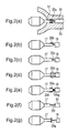
- Figures 2(a) - 2(g) each show a portion of the first embodiment of a super-high pressure discharge lamp of the short arc type of the invention in the area in which an electrode is connected to a foil;
- Figure 3 is a partial side view of the first embodiment of a super-high pressure discharge lamp of the short arc type according to the invention in the area in which an electrode is connected to a foil;
- Figure 4 shows an end view of the portion of the first embodiment of a super-high pressure discharge lamp of the short arc type according to the invention in the area in which an electrode is connected to a foil;
- Figure 5 a graph representing the action of the first embodiment of a super-high pressure discharge lamp of the short arc type in accordance with the invention
- Figure 6 is a partial sectional view of another version of the first embodiment of a super-high pressure discharge lamp of the short arc type in accordance with the invention.
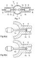
- Figure 7 is an overall cross-sectional view of a second embodiment of a super-high pressure discharge lamp of the short arc type of the invention.
- Figures 8(a) & 8(b) each show an enlarged representation of the anode of a second embodiment of the super-high pressure discharge lamp of the short arc type in accordance with the invention
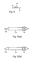
- Figure 9 shows an enlarged representation of the weld of the metal foil of the second embodiment of the super-high pressure discharge lamp of the short arc type according to the invention.
- Figures 10(a) & 10(b) each show an enlarged representation of the cathode of the second embodiment of the super-high pressure discharge lamp of the short arc type in accordance with the invention.
- a connecting point to the metal foil is formed using a metallic component with a smaller diameter. Therefore, formation and growth of cracks at this connecting point can be advantageously suppressed. It has been found that, with welding to the metal foil in the side tube portion, crack formation at this connecting point can be suppressed by placing a metallic component, as an individual body, between the electrode rod and the metal foil and by reducing the outside diameter of this metal component to 0.1 mm to 0.5 mm, instead of welding the electrode rod and the metal foil to one another, as is conventional.
- the super-high pressure discharge lamp of the short arc type as in accordance with the invention is subject to extremely strict thermal conditions, the internal air pressure during operation being 15 MPa, the internal volume of the arc tube being roughly 80 mm 3 and the value of the wall load being at least 0.8 W/mm 2 .
- the electrodes extend from the discharge space to the side tube portions with an essentially identical size, however, the action of heat transfer from the electrode rod takes effect to a sufficient degree and the high temperature within the discharge space is advantageously subjected to heat dissipation from the side tube portions.
- the electrode rods extend, for the heat dissipation effect, unchanged in the thick state as far as to the side tube portions, and only when there is a connection to the metal foils is each metallic component used as an individual body in order to prevent formation of gaps.
- the electrode rods discharge the high temperature of the discharge space as conduction heat as far as the side tubes, and in these side tube portions, it is subjected to heat dissipation from the outside peripheral surfaces of the electrode rods via the silica glass.
- the electrodes as parts with a larger diameter extend in the areas which are opposite the side tube portions.
- these electrodes discharge the high temperature of the discharge space as conduction heat as far as the side tubes, and in these side tube portions, it can be advantageously subjected to heat dissipation from the outer peripheral surfaces of the electrode rods via the material components of the side tube portions, for example, via the silica glass.
- the electrodes At the welds, with the metal foils on the electrode tips, the electrodes have a smaller diameter. Therefore, the inevitable gaps which arise when the electrodes are welded to the metal foils become smaller, and in this way, increase the pressure tightness in the side tube portions.
- the numerical values are shown below.
- FIG. 1 shows the overall arrangement of a first embodiment of the super-high pressure discharge lamp of the short arc type of the invention (hereinafter also called only a "discharge lamp").
- a discharge lamp 10 has an essentially spherical discharge space 12 which is formed by a silica glass discharge vessel 11.
- a cathode 13 is disposed opposite an anode 14 supported on an end of a respective electrode rod 17.
- hermetically sealed portions 15 in which metal foils 16, which normally are made of molybdenum, are hermetically installed, for example, by a pinch seal.
- the base parts of the electrode rods 17 are each located on an end of the metal foil 16, welded and electrically connected, while a respective outer lead pin 18, which extends outward from the sealed portion 15, is welded on the other end of the metal foil 16.
- electrodes is defined as the cathode 13, the anode 14 and the electrode rods 17.
- the main component of which the electrodes are formed is tungsten.
- a metallic component 20 which is an individual body which is different from the electrode rod 17.
- This metallic component 20 is made of molybdenum or a material with molybdenum as the main component, as is described below.
- the cross sectional area of the metallic component 20 is smaller than the cross sectional area of the electrode rod 17.
- the metallic component 20 acts as a bridge between the electrode rod 17 and the metal foil 16 in the sense of a feed function, by which the two are electrically connected to one another.
- the discharge space 12 is filled with mercury, a rare gas, and halogen gas.
- the mercury is used to obtain the necessary wavelengths of visible light, for example, to obtain radiant light with wavelengths from 360 nm to 780 nm, and is contained in an amount of at least 0.15 mg/mm 3 .
- the internal pressure of course, differs depending on the temperature condition. However, an extremely high vapor pressure is achieved at a pressure during operation of at least 15 MPa.
- a discharge lamp with a high mercury vapor pressure during operation of at least 20 MPa or 30 MPa can be produced.
- the rare gas for example, roughly 13 kPa argon gas is added.
- the rare gas is used to improve the operating starting property.
- halogen bromine, chorine, iodine or the like in the form of a compound with mercury or other metals is added.
- the amount of halogen added can be chosen, for example, from the range of 10 -6 ⁇ mole/mm 3 to 10 -2 ⁇ mole/mm 3 . Its function is to prolong the service life by preventing milky opacification of the discharge vessel or for similar purposes. In an extremely small discharge vessel with a high internal pressure, as in the discharge lamp of the invention, this addition of a halogen affects the phenomenon of preventing damage and devitrification of the discharge vessel.
- the wall load of the discharge lamp is at least 0.8 W/mm 2 .
- the reason for this is that the discharge vessel contains a large amount of mercury so that the thermal condition for vaporization of this mercury is adequately met during lamp operation.
- the internal volume of the discharge lamp is small, i.e., at most 80 mm 3 .
- the reason for this is that there is a demand for reducing the size of the discharge lamp as much as possible according to the reduction in size of the liquid crystal projector device.
- This discharge lamp is installed in the above described projector device and in a display device such as an overhead projector or the like and can emit radiant light with good color reproduction.
- Figures 2(a) to 2(g) each show the base point of the anode in an enlarged representation, in which, between the electrode and the metal foil of the discharge lamp, there is a bridge in accordance with the first embodiment of the invention.
- Figures 2(a) to 2(g) show specific versions as examples. Starting with Figure 2(b), the silica glass is not shown, but is provided as represented in Figure 2(a).
- a metallic component 20a as the individual body, which is formed of a metallic wire.
- One end of the wire is wound a few times around an end of the electrode rod and its other end is welded to the metal foil.
- the metallic component 20b is not a wire, but rather is formed of a bent rod-shaped component. One end of this metallic component 20b is spot-welded to one end of the electrode rod. Likewise, the other end of the metallic component 20b is spot-welded to the metal foil.
- the metallic component 20c is a straight, rod-shaped component. One end of the metallic component 20c is inserted into an opening which is located in the center of an end of the electrode rod and attached. The other end of the metallic component 20c is welded to the metal foil 16.
- the metallic component 20d is formed of a conductive wire, and the electrode rod 17 is provided with a through opening 170 through which the conductive wire passes.
- the two ends of the conductive wire are each welded to the metal foil 16.
- This arrangement has the advantage that the metallic component 20d can be formed with a cross sectional area which is only half as large as the cross sectional area of the metallic components which are shown above in Figures 2 (a) to (c) and that the same overall cross sectional area is obtained by the arrangement of two metallic leads.
- the metallic component 20e comprises a conductive spring part (coil part) 20e 1 and a rod-shaped, conductive component 20e 2 .
- the conductive spring part 20e 1 has a first portion that is wound around the electrode rod and a second portion which is wound around the rod-shaped, conductive component 20e 2 .
- This arrangement is held by means of the spring force of the conductive springs 20e 1 on the electrode rod 17.
- the conductive component 20e 2 is held by the spring force.
- the other end of the conductive component 20e 2 is welded to the metal foil 16.
- the metallic component 20f is a straight, rod-shaped component. One end of the metallic component 20f is welded to a flat area formed on the electrode rod by cutting it off. The other end of the metallic component 20f is welded to metal foil 16.
- the metallic component 20g is a straight, rod-shaped component which is welded to the electrode rod 17.
- the electrode rod 17 has a diameter from 0.6 mm to 1.5 mm.
- the metallic component 20 has a diameter from 0.1 mm to 0.5 mm. Specific numerical values are described by way of example below:
- FIGs 2(a) to 2(g) show arrangements in which the electrode rod 17 is shorter than the anode 14.
- the electrode rod 17 is however in reality somewhat longer. It is furthermore necessary for the side tube portion to be formed from silica glass in the external vicinity of the electrode rod 17. The reason for this is that heat dissipation from the outer peripheral surface of the electrode rod via the silica glass becomes important.
- Figure 3 shows an enlarged representation of the base point of the cathode of the super-high pressure discharge lamp of the first embodiment of the invention.
- the metal foil is not shown.
- a metallic component 17b with a smaller outside diameter than the outside diameter of the electrode rod is connected to an end of the electrode rod 17a of the cathode 13.
- the other end of the metallic component 17b is connected to a metal foil which is not shown in the drawings.
- the metallic component 17b can be of any of the arrangements shown in Figures 2(a) to 2(g). In this embodiment, however, the arrangement shown in Figure 2(f) is shown by way of example.
- the numerical values are described below by way of example:
- the cathode in contrast to the anode, the electrode and the electrode rod are not distinguished from one another, so that the two as a whole are called “electrode.”
- the electrode can be distinguished from the electrode rod and can also be called the electrode rod separately.
- the cathode can also have an arrangement in which the tip is provided with an electrode head with a larger diameter, as in the anode.
- the coil wound around the cathode tip is used to improve the operating starting property.
- the arrangement of the cathode is shown specifically below.
- the diameter of the electrode rod 17a is 0.8 mm
- the length (the distance from the tip) is 8.0 mm
- the diameter of the metallic component 17b is 0.14 mm
- its length is 1.8 mm.
- FIG 4 shows the point at which the metallic component 20 is connected to the metal foil 16 in an enlarged representation.
- a gap D is inevitably formed. If a high gas pressure within the discharge space is applied to this gap D, cracks are caused to form and grow.
- the inventors have ascertained that such a gap D is greatly influenced by the outside diameter of the metallic component 20. This means that the gap D does not become larger than the cross sectional area of the metallic component. That the metallic component 20 is small, of course, means that the gap D is also small.
- Figure 5 shows the measurement of the relation between the outside diameter of the metallic component 20 and the pressure applied to this gap D in the case of changing only the outside diameter of the metallic component 20 in a discharge lamp, as was shown, by way of example, in the above described embodiment.
- the y-axis plots the pressure of the gas applied to the gap and the x-axis plots the outside diameter of the metallic component.
- the connecting point between the metallic component 20 and the metal foil has the arrangement shown in Figure 2(f).
- the discharge lamp has the arrangement described in conjunction with Figure 1.
- the amount of mercury added is 0.15 mg/mm 2 .
- the applied pressure is 80 MPa, in the case of an outside diameter of the metallic component of 0.7 mm, the applied pressure is roughly 48 MPa, in the case of an outside diameter of the metallic component of 0.5 mm, the applied pressure is roughly 42 MPa, and in the case of an outside diameter of the metallic component of 0.3 mm, the applied pressure is roughly 36 MPa. Since the electrode rod has a diameter of 1.0 mm, this diameter is identical to the outside diameter of the metallic component of 1.0 mm. This means that the arrangement of the connection of the invention by means of the metallic component as an individual body is not present.
- the metallic component 20 is normally formed with a circular cross section, in the above described tests, the measurements were taken such that the value of the outside diameter of the metallic component is regarded as a criterion. However, it goes without saying that essentially the cross-sectional area of the metallic component influences the size of the gap which forms during the connection.
- FIG. 6 shows another embodiment of the high pressure discharge lamp of the short arc type in accordance with the invention.
- the base point of the anode is shown enlarged.
- This arrangement has the feature that the outside surface of the electrode rod 17 is surrounded by a gap B.
- the reason for the arrangement of this gap is to advantageously prevent formation of cracks between the electrode rod and the silica glass in a discharge lamp which is filled with an extremely high mercury vapor pressure of 0.15 mg/mm 3 .
- the size of the gap is, for example, roughly 3 ⁇ m (microns) to 10 ⁇ m (microns), the action of heat dissipation from the surface of the electrode rod is adequately maintained.
- the arrangement is the same as in the above described embodiment, except that there is a gap B.
- the metallic component 20 acts as a bridge between the electrode rod 17 and the metal foil 16.
- the arrangement of the gap in itself is described in Japanese patent application 2000-168798 (corresponding to commonly-owned, co-pending published U.S. Application 20020031975 A1).
- the super-high pressure mercury lamps of the short arc type of the invention have an extremely high internal pressure during operation of greater than 15 MPa and are also subject to extremely strict thermal conditions.
- the metallic component is located as a bridge, the following is achieved:
- Figure 7 is a schematic of the overall arrangement of the second embodiment of the super-high pressure discharge lamp of the short arc type as claimed in the invention.
- the same parts as in Figure 1 are provided with the same reference numbers as in Figure 1.
- these gaps are not shown with respect to the representation of the overall arrangement of the lamp.
- FIGs 8(a) and 8(b) each are an enlarged representation of the anode of the second embodiment of the discharge lamp of the invention.
- the electrode 14 comprises a part 14a which is located in the discharge space with a larger diameter and of a part 14b which is located on the side of the metal foil with a smaller diameter.
- the parts 14a, 14b were formed by working from a single part. In the part 14b with a smaller diameter, a connection is made to the metal foil 16. Between the surface of part 14a with a larger diameter and the inner surface of the silica glass side tube portion 15, an extremely small gap A is formed.
- the part 14a with the larger diameter and the part 14b with a smaller diameter are formed step-shaped.
- the part 14b with the smaller diameter is located bordering the part 14a with the larger diameter, the part 14b having a tapering diameter which becomes increasingly smaller.
- the numerical values are described below by way of example.
- this electrode rod discharges the high temperature of the discharge space as conduction heat to the side tube portion and it can advantageously be subjected to heat dissipation proceeding from the outside peripheral surface of the electrode rod via the material component of the side tube portion, for example, via the silica glass.
- the gap which inevitably forms when the electrode is welded to the metal foil can be made smaller, and in this way, the pressure tightness in the side tube portion can be increased.
- Figure 9 shows the gap C which inevitably forms when the metal foil 16 is joined to the electrode rod 14b. As is apparent from Figure 9, the gap C is made smaller when the outside diameter of the electrode rod is small.
- Figures 10(a) and 10(b) each show an enlarged representation of the cathode of the super-high pressure discharge lamp of the invention.
- the cathode 13 also has a part 13a with a larger diameter and a part 13b with a smaller diameter.
- the part 13a with the larger diameter extends from the emission space to the side tube portion. Therefore, the high temperature in the arc tube portion can be discharged as conduction heat out of the side tube portion by heat dissipation.
- the part 13b with the smaller diameter a connection is made to the metal foil. As in the anode, the inevitable gap which forms during connection can be made smaller.
- the electrode and the electrode rod are not distinguished from one another, and as a whole, the two are called an electrode.
- the electrode rod can also be regarded as a separate part, or the electrode head with a larger diameter can be placed at the tip, as in the anode.
- a coil 13c which is wound around the cathode tip is used to improve the operating-starting property.
- the super-high pressure mercury lamp in the second embodiment of the invention has an extremely small gap A between the electrode rod and the inside surface of the side tube portion. Therefore, this gap A is provided so that the electrode, as a result of the differences between the coefficient of expansion of the material component of the electrode and the material comprising the side tube portion, is not confined, but it can expand freely in the axial direction.
- the width of the gap A is chosen from the range of 6 ⁇ m (microns) to 16 ⁇ m (microns); in the lengthwise direction of the electrode, there is a gap A of a length from 3 mm to 5 mm.
- the gap A at both electrodes, i.e., both in the cathode and also in the anode. However, this does not preclude there being a gap only at one of the electrodes.
- the electrodes have a part with a smaller diameter and a part with a larger diameter, and the part with the larger diameter extends in the area opposite the side tube portion. Therefore, the high temperature of the discharge space can be discharged as conduction heat as far as the side tubes and advantageously subjected to heat dissipation in these side tube portions from the outside peripheral surfaces of the electrode rods via the material component of the side tube portions, for example, via the silica glass.
- the electrodes have a smaller diameter at the welds to the metal foils on the electrode tips. Therefore, the inevitable gaps which form when the electrodes are welded to the metal foil can be made smaller, and thus, the pressure tightness in the side tube portions can be increased.
Landscapes
- Vessels And Coating Films For Discharge Lamps (AREA)
- Discharge Lamp (AREA)
Applications Claiming Priority (4)
| Application Number | Priority Date | Filing Date | Title |
|---|---|---|---|
| JP2001277917A JP3700628B2 (ja) | 2001-09-13 | 2001-09-13 | ショートアーク型超高圧放電ランプ |
| JP2001277917 | 2001-09-13 | ||
| JP2001280926A JP3622713B2 (ja) | 2001-09-17 | 2001-09-17 | ショートアーク型超高圧放電ランプ |
| JP2001280926 | 2001-09-17 |
Publications (3)
| Publication Number | Publication Date |
|---|---|
| EP1296356A2 true EP1296356A2 (de) | 2003-03-26 |
| EP1296356A3 EP1296356A3 (de) | 2006-01-25 |
| EP1296356B1 EP1296356B1 (de) | 2014-03-05 |
Family
ID=26622138
Family Applications (1)
| Application Number | Title | Priority Date | Filing Date |
|---|---|---|---|
| EP02020387.3A Expired - Lifetime EP1296356B1 (de) | 2001-09-13 | 2002-09-12 | Höchstdruck-Entladungslampe vom Kurzbogentyp |
Country Status (3)
| Country | Link |
|---|---|
| US (1) | US6713957B2 (de) |
| EP (1) | EP1296356B1 (de) |
| CN (1) | CN1407592A (de) |
Cited By (1)
| Publication number | Priority date | Publication date | Assignee | Title |
|---|---|---|---|---|
| WO2005017948A3 (en) * | 2003-08-15 | 2006-12-07 | Koninkl Philips Electronics Nv | Discharge lamp comprising electrodes having a conical slip part |
Families Citing this family (10)
| Publication number | Priority date | Publication date | Assignee | Title |
|---|---|---|---|---|
| JP2004031153A (ja) * | 2002-06-26 | 2004-01-29 | Matsushita Electric Ind Co Ltd | 高圧水銀ランプおよびランプユニット |
| JP4214826B2 (ja) * | 2003-04-22 | 2009-01-28 | ウシオ電機株式会社 | ショートアーク型超高圧放電ランプ |
| JP4325518B2 (ja) * | 2004-09-10 | 2009-09-02 | ウシオ電機株式会社 | 超高圧水銀ランプ |
| US7821209B2 (en) * | 2004-09-21 | 2010-10-26 | Sharp Kabushiki Kaisha | Light source unit, illumination apparatus for display apparatus, and display apparatus |
| KR101140746B1 (ko) * | 2004-09-30 | 2012-05-15 | 코닌클리즈케 필립스 일렉트로닉스 엔.브이. | 밀봉 호일을 갖는 전기 램프 |
| JP4358729B2 (ja) * | 2004-12-22 | 2009-11-04 | 株式会社オーク製作所 | ショートアーク型放電灯 |
| US7952283B2 (en) | 2005-11-09 | 2011-05-31 | General Electric Company | High intensity discharge lamp with improved crack control and method of manufacture |
| CN100433238C (zh) * | 2006-03-13 | 2008-11-12 | 成都三普电光源实业有限公司 | 用于超高压汞灯的高亮度电极 |
| CN100413015C (zh) * | 2006-03-13 | 2008-08-20 | 成都三普电光源实业有限公司 | 超高压汞灯 |
| JP4229166B2 (ja) * | 2006-10-16 | 2009-02-25 | セイコーエプソン株式会社 | 発光管、光源装置、及びプロジェクタ |
Citations (3)
| Publication number | Priority date | Publication date | Assignee | Title |
|---|---|---|---|---|
| JPH02148561A (ja) | 1988-04-21 | 1990-06-07 | Philips Gloeilampenfab:Nv | 高圧水銀蒸気放電ランプ |
| JPH0652830A (ja) | 1992-06-23 | 1994-02-25 | Philips Electron Nv | 高圧水銀放電ランプ |
| JPH10289690A (ja) | 1997-04-15 | 1998-10-27 | Matsushita Electric Ind Co Ltd | 高圧放電ランプ |
Family Cites Families (12)
| Publication number | Priority date | Publication date | Assignee | Title |
|---|---|---|---|---|
| JPS62157662A (ja) * | 1985-12-28 | 1987-07-13 | Toshiba Corp | 高圧放電灯 |
| EP0266821B1 (de) * | 1986-10-20 | 1991-01-02 | Koninklijke Philips Electronics N.V. | Hochdruckentladungslampe |
| DE3923589A1 (de) * | 1989-07-17 | 1991-01-24 | Patent Treuhand Ges Fuer Elektrische Gluehlampen Mbh | Hochdruckentladungslampe |
| JP2940829B2 (ja) | 1989-12-28 | 1999-08-25 | ウシオ電機株式会社 | 耐高圧力箔シール構造 |
| DE19727430A1 (de) * | 1997-06-27 | 1999-01-07 | Patent Treuhand Ges Fuer Elektrische Gluehlampen Mbh | Metallhalogenidlampe mit keramischem Entladungsgefäß |
| JP3562271B2 (ja) * | 1997-11-07 | 2004-09-08 | ウシオ電機株式会社 | ショートアークランプ |
| JP2000057994A (ja) * | 1998-08-04 | 2000-02-25 | Stanley Electric Co Ltd | ダブルエンド型低電力メタルハライドランプ |
| JP4388699B2 (ja) * | 1998-08-13 | 2009-12-24 | コーニンクレッカ フィリップス エレクトロニクス エヌ ヴィ | コーティングされた外部電流導体を有する電気ランプ |
| JP3118758B2 (ja) * | 1998-10-19 | 2000-12-18 | ウシオ電機株式会社 | ランプ用傾斜機能材料製封止体およびランプ |
| JP3503575B2 (ja) | 2000-06-06 | 2004-03-08 | ウシオ電機株式会社 | ショートアーク型超高圧放電ランプ及びその製造方法 |
| JP3591439B2 (ja) * | 2000-09-21 | 2004-11-17 | ウシオ電機株式会社 | ショートアーク放電ランプ |
| EP1271595B1 (de) * | 2001-06-13 | 2013-06-05 | Ushiodenki Kabushiki Kaisha | Ultrahochdruck-Entladungslampe vom Kurzbogentyp |
-
2002
- 2002-09-12 EP EP02020387.3A patent/EP1296356B1/de not_active Expired - Lifetime
- 2002-09-12 US US10/241,644 patent/US6713957B2/en not_active Expired - Lifetime
- 2002-09-13 CN CN02142977.4A patent/CN1407592A/zh active Pending
Patent Citations (5)
| Publication number | Priority date | Publication date | Assignee | Title |
|---|---|---|---|---|
| JPH02148561A (ja) | 1988-04-21 | 1990-06-07 | Philips Gloeilampenfab:Nv | 高圧水銀蒸気放電ランプ |
| US5109181A (en) | 1988-04-21 | 1992-04-28 | U.S. Philips Corporation | High-pressure mercury vapor discharge lamp |
| JPH0652830A (ja) | 1992-06-23 | 1994-02-25 | Philips Electron Nv | 高圧水銀放電ランプ |
| US5497049A (en) | 1992-06-23 | 1996-03-05 | U.S. Philips Corporation | High pressure mercury discharge lamp |
| JPH10289690A (ja) | 1997-04-15 | 1998-10-27 | Matsushita Electric Ind Co Ltd | 高圧放電ランプ |
Cited By (1)
| Publication number | Priority date | Publication date | Assignee | Title |
|---|---|---|---|---|
| WO2005017948A3 (en) * | 2003-08-15 | 2006-12-07 | Koninkl Philips Electronics Nv | Discharge lamp comprising electrodes having a conical slip part |
Also Published As
| Publication number | Publication date |
|---|---|
| EP1296356B1 (de) | 2014-03-05 |
| US6713957B2 (en) | 2004-03-30 |
| US20030048076A1 (en) | 2003-03-13 |
| CN1407592A (zh) | 2003-04-02 |
| EP1296356A3 (de) | 2006-01-25 |
Similar Documents
| Publication | Publication Date | Title |
|---|---|---|
| US6903509B2 (en) | Ultrahigh pressure discharge lamp of the short arc type with improved metal foil to electrode connection arrangement | |
| US20010010447A1 (en) | Short-arc type discharge lamp | |
| EP1296356B1 (de) | Höchstdruck-Entladungslampe vom Kurzbogentyp | |
| US6861806B2 (en) | Super-high pressure discharge lamp of the short arc type | |
| US6911775B2 (en) | Short-arc, ultra-high pressure discharge lamp | |
| US7176631B2 (en) | Ultra high pressure discharge lamp | |
| JP4750550B2 (ja) | メタルハライドランプ | |
| JP2007134055A (ja) | 放電ランプ装置用アークチューブ | |
| JP2005515592A (ja) | 放電ランプ | |
| JP4431174B2 (ja) | 高圧ガス放電ランプ | |
| EP1324373B1 (de) | Superhochdruck-Entladungslampe vom Kurzbogentyp | |
| EP1353357B1 (de) | Ultrahochdruck-Quecksilberlampe | |
| EP1729325B1 (de) | Ultrahochdruck-Quecksilberlampe | |
| KR20010023389A (ko) | 고압 가스 방전 램프 | |
| US7170230B2 (en) | Mercury-free arc tube for a discharge lamp | |
| JP2002270133A (ja) | 超高圧放電灯用電極と該電極を使用した超高圧放電灯 | |
| JP2004039349A (ja) | 高圧放電ランプ及び光源ユニット | |
| JPH11162406A (ja) | 高圧放電ランプおよび投光装置ならびにプロジェクタ装置 | |
| JPH0896750A (ja) | 高圧放電灯、放電灯点灯装置および光源装置 | |
| JP4587118B2 (ja) | ショートアーク放電ランプ | |
| JP2001345071A (ja) | 高圧放電ランプおよび照明装置 | |
| JP3700628B2 (ja) | ショートアーク型超高圧放電ランプ | |
| JP4900870B2 (ja) | 放電ランプ、放電ランプを用いた投影用光源装置及び画像投影装置 | |
| US20080111488A1 (en) | Quartz metal halide lamp with improved structural and electrical properties |
Legal Events
| Date | Code | Title | Description |
|---|---|---|---|
| PUAI | Public reference made under article 153(3) epc to a published international application that has entered the european phase |
Free format text: ORIGINAL CODE: 0009012 |
|
| AK | Designated contracting states |
Kind code of ref document: A2 Designated state(s): AT BE BG CH CY CZ DE DK EE ES FI FR GB GR IE IT LI LU MC NL PT SE SK TR |
|
| AX | Request for extension of the european patent |
Extension state: AL LT LV MK RO SI |
|
| PUAL | Search report despatched |
Free format text: ORIGINAL CODE: 0009013 |
|
| AK | Designated contracting states |
Kind code of ref document: A3 Designated state(s): AT BE BG CH CY CZ DE DK EE ES FI FR GB GR IE IT LI LU MC NL PT SE SK TR |
|
| AX | Request for extension of the european patent |
Extension state: AL LT LV MK RO SI |
|
| 17P | Request for examination filed |
Effective date: 20060306 |
|
| AKX | Designation fees paid |
Designated state(s): DE GB NL |
|
| 17Q | First examination report despatched |
Effective date: 20101110 |
|
| GRAP | Despatch of communication of intention to grant a patent |
Free format text: ORIGINAL CODE: EPIDOSNIGR1 |
|
| INTG | Intention to grant announced |
Effective date: 20131204 |
|
| GRAS | Grant fee paid |
Free format text: ORIGINAL CODE: EPIDOSNIGR3 |
|
| GRAA | (expected) grant |
Free format text: ORIGINAL CODE: 0009210 |
|
| AK | Designated contracting states |
Kind code of ref document: B1 Designated state(s): DE GB NL |
|
| REG | Reference to a national code |
Ref country code: GB Ref legal event code: FG4D |
|
| REG | Reference to a national code |
Ref country code: DE Ref legal event code: R096 Ref document number: 60246038 Country of ref document: DE Effective date: 20140417 |
|
| REG | Reference to a national code |
Ref country code: NL Ref legal event code: T3 |
|
| REG | Reference to a national code |
Ref country code: DE Ref legal event code: R097 Ref document number: 60246038 Country of ref document: DE |
|
| PLBE | No opposition filed within time limit |
Free format text: ORIGINAL CODE: 0009261 |
|
| STAA | Information on the status of an ep patent application or granted ep patent |
Free format text: STATUS: NO OPPOSITION FILED WITHIN TIME LIMIT |
|
| 26N | No opposition filed |
Effective date: 20141208 |
|
| REG | Reference to a national code |
Ref country code: DE Ref legal event code: R097 Ref document number: 60246038 Country of ref document: DE Effective date: 20141208 |
|
| PGFP | Annual fee paid to national office [announced via postgrant information from national office to epo] |
Ref country code: GB Payment date: 20160907 Year of fee payment: 15 Ref country code: DE Payment date: 20160907 Year of fee payment: 15 |
|
| REG | Reference to a national code |
Ref country code: DE Ref legal event code: R119 Ref document number: 60246038 Country of ref document: DE |
|
| GBPC | Gb: european patent ceased through non-payment of renewal fee |
Effective date: 20170912 |
|
| PG25 | Lapsed in a contracting state [announced via postgrant information from national office to epo] |
Ref country code: GB Free format text: LAPSE BECAUSE OF NON-PAYMENT OF DUE FEES Effective date: 20170912 Ref country code: DE Free format text: LAPSE BECAUSE OF NON-PAYMENT OF DUE FEES Effective date: 20180404 |
|
| PGFP | Annual fee paid to national office [announced via postgrant information from national office to epo] |
Ref country code: NL Payment date: 20190814 Year of fee payment: 18 |
|
| REG | Reference to a national code |
Ref country code: NL Ref legal event code: MM Effective date: 20201001 |
|
| PG25 | Lapsed in a contracting state [announced via postgrant information from national office to epo] |
Ref country code: NL Free format text: LAPSE BECAUSE OF NON-PAYMENT OF DUE FEES Effective date: 20201001 |