EP1296438A2 - Rotierende elektrische Maschine - Google Patents
Rotierende elektrische Maschine Download PDFInfo
- Publication number
- EP1296438A2 EP1296438A2 EP02010116A EP02010116A EP1296438A2 EP 1296438 A2 EP1296438 A2 EP 1296438A2 EP 02010116 A EP02010116 A EP 02010116A EP 02010116 A EP02010116 A EP 02010116A EP 1296438 A2 EP1296438 A2 EP 1296438A2
- Authority
- EP
- European Patent Office
- Prior art keywords
- field winding
- rotor
- organic fibers
- contact
- fibers
- Prior art date
- Legal status (The legal status is an assumption and is not a legal conclusion. Google has not performed a legal analysis and makes no representation as to the accuracy of the status listed.)
- Granted
Links
Images






Classifications
-
- H—ELECTRICITY
- H02—GENERATION; CONVERSION OR DISTRIBUTION OF ELECTRIC POWER
- H02K—DYNAMO-ELECTRIC MACHINES
- H02K3/00—Details of windings
- H02K3/30—Windings characterised by the insulating material
-
- H—ELECTRICITY
- H02—GENERATION; CONVERSION OR DISTRIBUTION OF ELECTRIC POWER
- H02K—DYNAMO-ELECTRIC MACHINES
- H02K3/00—Details of windings
- H02K3/32—Windings characterised by the shape, form or construction of the insulation
- H02K3/40—Windings characterised by the shape, form or construction of the insulation for high voltage, e.g. affording protection against corona discharges
-
- H—ELECTRICITY
- H02—GENERATION; CONVERSION OR DISTRIBUTION OF ELECTRIC POWER
- H02K—DYNAMO-ELECTRIC MACHINES
- H02K3/00—Details of windings
- H02K3/46—Fastening of windings on the stator or rotor structure
- H02K3/48—Fastening of windings on the stator or rotor structure in slots
Definitions
- the present invention relates to a rotary electric machine for mounting on a turbine generator and the like.
- a rotary electric machine has a cylindrical rotor with slots formed in its circumference at equal intervals, as shown in Fig. 1 to Fig. 3 (details will be described later). Inserted in each of the slots are a field winding, a creepage block for insulating the field winding, and a wedge for preventing the field winding from coming off.
- the field winding When, upon energization of the field winding, the rotor incorporating the creepage block rotates at high speed, the field winding is subjected to heat produced by electric current flowing therein and a high surface pressure from the creepage block and wedge produced by a large centrifugal force of rotation and is therefore thermally elongated.
- Means for addressing the problem of the rotor shaft bending described above are disclosed in, for example, JP-6-86492A, JP-7-163075A and JP-8-322180A.
- a sheet which is made of graphite and covered with polytetrafluoroethylene, is interposed between the most radially external turn of the field winding and the next most external turn to improve the slippage between the adjoining turns of the field winding.
- JP-7-163075A comprises a field winding received in each coil slot, a wedge inserted into an opening of the slot to firmly hold the field winding in the slot, and a low-friction coefficient material, such as aramid paper, coated with polytetrafluoroethylene and interposed between the wedge and the field winding to improve the slippage of the field winding.
- a low-friction coefficient material such as aramid paper
- a low-friction coefficient material such as polytetrafluoroethylene, is integrally formed between the wedge and the field winding in the rotary slot to improve the slippage of the filed winding.
- JP-6-86492A, JP-7-163075A and JP-8-322180A are the examples of attempting to reduce a frictional force acting on the field winding and therefore the shaft bending force by inserting a member coated with a friction coefficient reducing agent, such as polytetrafluoroethylene, into a contact portion that engages the field winding or by integrally molding such a member and the contact portion.
- a friction coefficient reducing agent such as polytetrafluoroethylene
- An object of the present invention is to provide a rotary electric machine which minimizes frictional force variations caused by the field winding of the rotor being thermally expanded and thereby reduces the bending of the rotor shaft even when the thermal expansion of the field winding repetitively occurs.
- a rotary electric machine which comprises a stator frame, a rotor mounted on the stator frame through bearings, a plurality of slots formed in an outer circumferential surface of the rotor; a field winding installed in the slots, and creepage blocks for electric insulation supported in openings of the rotor in contact with the field winding, wherein each of the creepage blocks is formed by pressing together a resin member containing reinforcement fibers and organic fibers for contact with the field winding.
- a rotary electric machine which comprises a stator frame, a rotor mounted on the stator frame through bearings, a plurality of slots formed in an outer circumferential surface of the rotor, a field winding installed in the slots, and creepage blocks for electric insulation supported in openings of the rotor in contact with the field winding, wherein each of the creepage blocks comprises prepreg sheets and organic fibers for contact with the field winding, the prepreg sheets having reinforcement fibers aligned in a direction, impregnated with semi-hardened resin and fixed together, and the organic fibers for contact with the field winding are oriented to a direction of axis of the rotor.
- each of the creepage blocks comprises prepreg sheets and organic fibers for contact with the field winding, the prepreg sheets having reinforcement fibers that are aligned in a direction, impregnated with semi-hardened resin and fixed together, and the organic fibers are short and directed in random directions.
- the above objective can also be achieved by a rotary electric machine wherein the organic fibers for contact with the field winding include fibers made from polybenzoimidazole, polyparaphenylene benzobisoxazole, aromatic polyamide, polyarylate, and aromatic polyester.
- the above objective can also be realized by a rotary electric machine wherein the organic fibers for contact with the field winding include fibers with a heat resistance of 300°C or higher.
- the above objective can also be realized by a rotary electric machine wherein a surface of the organic fibers for contact with the field winding is combined with fibers made from polyethylene, polypropylene and nylon.
- the above objective can also be realized by a rotary electric machine wherein the surface of the organic fibers for contact with the field winding is machined so that the organic fibers are exposed at the surface.
- the above objective can also be realized by a rotary electric machine wherein the surface of the organic fibers for contact with the field winding has a thickness equal to or less than one fourth the thickness of the creepage block.
- each of the creepage blocks is formed with holes extending in a direction of a thickness of the block and members containing organic fibers are inserted in the holes.
- Fig. 1 is a perspective view of a rotary electric machine.
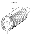
- Fig. 2 is a perspective view of a rotor.
- Fig. 3 is an enlarged perspective view of portion A in Fig. 2.
- Fig. 4 is a perspective view showing reinforced fiber layers in a creepage block.
- Fig. 5 is a perspective view showing reinforced fiber layers in a creepage block as another embodiment.
- Fig. 6 is a perspective view showing reinforced fiber layers in a creepage block as still another embodiment.
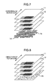
- Fig. 7 is a perspective view showing reinforced fiber layers in a creepage block as a further embodiment.
- Fig. 8 is a perspective view showing reinforced fiber layers in a creepage block as a further embodiment.
- Fig. 9 is a perspective view showing reinforced fiber layers in a creepage block as a further embodiment.
- Fig. 10 is a perspective view showing reinforced fiber layers in a creepage block as a further embodiment.
- Fig. 11 is a graph showing a relation among a percentage of an organic fiber layer thickness in a creepage block, a compressive strength of the creepage block, and a friction coefficient stability.
- Fig. 12 is a graph showing a relation between a friction coefficient and the number of slippages for members assembled into the rotor.
- Fig. 13 is a perspective view of a prepreg sheet roll.
- Fig. 14 is a perspective view of the creepage block cut from laminated prepreg sheets.
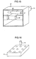
- Fig. 15 is a perspective view of a creepage block processing apparatus.
- Fig. 16 is a perspective view of a creepage block.
- Fig. 17 is a perspective view of another creepage block.
- turbine generators and the like are generally placed in service for a long period of time as long as they do not fail. During the service, however, starting and stopping are repeated, and the resulting impacts are considered to act on the respective slots and produce imbalances in friction resistance among the slots.
- the turbine generator is normally installed horizontally and thus its rotor shaft rotates in a horizontal direction. It is considered that, if the frictional resistance imbalances among the slots adversely affect the rotor shaft and bend it, the bending oscillates in a vertical direction, further amplifying the imbalances of frictional resistance.
- this invention seeks to reduce wear of the field winding as much as possible to minimize the forming of copper particles.
- Fig. 1 is a perspective view of a rotary electric machine, which is partly cut away so that the interior thereof can be seen.
- reference numeral 1 denotes a rotor of a cylindrical shape, through which a rotary shaft is inserted at an axial center thereof.
- 2 is a stator frame for fixing the stator, which is formed to enclose the outer circumference of the rotor 1.
- 3 are bearings provided at two positions inside the stator frame 2 to rotatably support the rotor 1.
- Fig. 2 is a perspective view of the rotor.
- the rotor 1 is cylindrical in its axial direction. In its outer circumference the rotor 1 has axially extending slots 5 formed at equal intervals. In these slots 5 a field winding 4 is installed. Machining these slots 5 forms comb-shaped teeth 6 between the slots 5.
- the rotor 1 has magnetic pole portions 7, 7' with no slots 5 formed therein. Although in this embodiment two of such magnetic pole portions are provided, they may be formed at four locations.
- a wedge 8 is fitted between the teeth 6 of the rotor 1 to prevent the field winding 4 from coming off in the radial direction by a centrifugal force during rotation.
- Fig. 3 is an enlarged view of portion A in Fig. 2.
- a resin plate called slot armor 9 for electric insulation is attached to each inner side wall of the slots separated by the teeth 6.
- the field winding 4 has a rectangular cross section. A plurality of turns of the field winding 4 are stacked one upon the other. Between the adjoining turns an interlayer insulating material 10 is interposed. The outermost turn of the field winding 4 engages a creepage block 11 for electric insulation and is held against a centrifugal force during the rotation by the wedge 8 supported between the teeth 6.
- Fig. 4 is a perspective view of reinforced fiber layers that form the creepage block 11.
- the creepage block 11 comprises a combination of a plurality of prepreg sheets 12 and organic fibers 13 attached to that side of the prepreg sheets which is for contact with the field winding.
- Each prepreg sheet is made from cloth of perpendicularly woven glass fibers impregnated with semi-hardened epoxy resin, and the thus formed prepreg sheets 12 are piled one upon another and pressed together by press plates under pressure and heat.
- Those of the organic fibers 13 on the surface side extend in the same direction as the axis of the rotor 1.
- the glass fiber cloth is made by weaving fibers extending in a direction of the rotor axis and fibers extending in a direction perpendicular to the rotor axis.
- the glass fibers and the organic fibers 13 are impregnated with the same epoxy resin and are integrally formed under pressure and heat as a base material of the creepage block 11.
- fibers that may be used as the organic fibers 13 are those made from polybenzoimidazole, polyparaphenylenebenzobisoxazole, aromatic polyamide, polyarylate, and aromatic polyester.
- These fibers have a heat resistance of 300°C or higher so that when the field winding 4 is energized and its temperature rise causes the field winding to expand in the direction of axis of the rotor 1, these fibers are not destroyed by the frictional heat and maintain a stable frictional state. Hence, they can prevent the field winding 4 from being galled and producing copper particles.
- Fig. 5 is a perspective view showing reinforced fiber layers forming the creepage block as another embodiment of the invention.
- the creepage block 11 is a combination of a laminated prepreg sheet 12 and organic fibers 13 attached to that side of the prepreg sheets which is for contact with the field winding.
- Each prepreg sheet is made from cloth of perpendicularly woven glass fibers impregnated with semi-hardened epoxy resin, and the thus formed prepreg sheets 12 are piled one upon another and pressed together by press plates under pressure and heat.
- the fabric of organic fibers 13 is made by weaving bundles of several fibers.
- Fig. 6 is a perspective view showing reinforced fiber layers forming the creepage block as still another embodiment.
- the creepage block 11 comprises a combination of a plurality of prepreg sheets 12 and organic fibers 13 attached to that side of the prepreg sheets which is for contact with the field winding.
- Each prepreg sheet is made from cloth of perpendicularly woven glass fibers impregnated with semi-hardened epoxy resin, and the thus formed prepreg sheets 12 are piled one upon another and pressed together by press plates under pressure and heat.
- the organic fibers 13 form a face contacting with the field winding 4 and extend in the same direction with that of the rotor axis. If this construction comprises only the fibers 13 extending in the rotor axis, there is a fear that the organic fibers will be split in the fiber direction. However, since they are combined with the prepreg sheets 12 comprising the glass fibers extending in the axis direction and those extending in a direction perpendicular to the rotor axis, the organic fibers 13 are provided with a sufficient strength and can prevent the splitting.
- the field winding 4 when the field winding 4 is energized and expands in the rotor axis direction by heat, since the organic fibers of the creepage block 11 extend in the same direction as the rotor axis, the field winding 4 can be slid smoothly, reducing the friction coefficient and minimizing the forming of copper particles from the field winding 4.
- Fig. 7 is a perspective view showing reinforced fiber layers forming the creepage block as a further embodiment of the invention.
- the creepage block 11 comprises a combination of a plurality of prepreg sheets 12 and organic fibers 14, 15 attached to that side of the prepreg sheets which is for contact with the field winding.
- Each prepreg sheet is made from cloth of perpendicularly woven glass fibers impregnated with semi-hardened epoxy resin, and the thus formed prepreg sheets 12 are piled one upon another and pressed together by press plates under pressure and heat.
- the organic fibers are woven in such a way that the number of organic fibers 14 arranged on a side for contact with the field winding 4 is larger than the number of organic fibers 15 extending in a direction perpendicular to that of the rotor axis.
- the organic fibers 14 to be provided in a greater number may be in only one layer which is for contact with the field winding 4. Alternatively, they may be arranged in a plurality of layers including that layer for contact with the field winding 4.
- the fibers may be woven in a plain weave or a satin weave.
- woven on that side of the creepage block 11 which is in contact with the field winding 4 are reinforcement fibers (glass fibers) harder than the field winding 4.
- the number of the organic fibers continuously arranged in the direction in which the field winding expands by heat is larger than the number of the glass fibers arranged in the direction perpendicular to that of the thermal expansion.
- the glass fibers extending in the perpendicular direction to the rotor axis restrain the organic fibers in the rotor axis direction so that the organic fibers will not separate from each other, it is possible to provide the creepage block that is highly reliable also in terms of strength.
- Fig. 8 is a perspective view of reinforced fiber layers that form the creepage block as a further embodiment of the invention.
- the creepage block 11 comprises a combination of a plurality of prepreg sheets 12 and organic fibers 15 attached to that side of the prepreg sheets which is for contact with the field winding.
- Each prepreg sheet is made from cloth of perpendicularly woven glass fibers impregnated with semi-hardened epoxy resin, and the thus formed prepreg sheets 12 are piled one upon another and pressed together by press plates under pressure and heat.
- the organic fibers 15 are cut short to about 1 mm to 10 mm and formed into a fabric, which is impregnated with the same epoxy resin together with the prepreg sheets 12 containing glass fibers.
- the organic fibers 15 may be made from polybenzoimidazole, polyparaphenylenebenzobisoxazole, aromatic polyamide, polyarylate, and aromatic polyester. These fibers have a heat resistance of 300°C or higher so that when the field winding 4 is energized and its temperature rise causes the field winding to expand in the direction of the axis of the rotor 1, these fibers are not destroyed by the frictional heat and maintain a stable frictional state.
- the organic fibers of the creepage block 11 on the side that is in contact with the field winding 4 stabilize the friction coefficient between the creepage block 11 and the field winding 4, so that when the field winding 4 is energized and its temperature rise causes the field winding to expand in the direction of the axis of the rotor 1, the field winding 4 can slide smoothly along the surface of the creepage block 11 even under high surface pressure. This in turn reduces frictional coefficient variations among the coil slots.
- a rotor in which the field winding has small frictions and in which there are small friction coefficient variations even when the field winding undergoes repetitive thermal expansions. Further, since the organic fibers are cut short, the organic fiber layer can be formed without having to consider the alignment of the fiber layer. This in turn reduces the manufacturing cost.
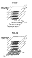
- Fig. 9 is a perspective view of reinforced fiber layers that form the creepage block as a further embodiment of the invention.
- the creepage block 11 is a combination of a plurality of prepreg sheets 12 and organic fibers 16 attached to that side of the prepreg sheets which is for contact with the field winding.
- Each prepreg sheet is made from cloth of perpendicularly woven glass fibers impregnated with semi-hardened epoxy resin, and the thus formed prepreg sheets 12 are piled one upon another and pressed together by press plates under pressure and heat.
- On the side for contact with the field winding 4 a plurality of bundles of two or more organic fibers 16 are provided.
- the fabric of organic fibers 16 may be formed by simply stacking together fiber bundles extending in the direction of the rotor axis and those extending in a direction perpendicular to the rotor axis or by weaving them together.
- the organic fiber bundles 16 and the glass fiber layers 12 are impregnated with the same epoxy resin.
- the organic fibers 16 may be made from polybenzoimidazole, polyparaphenylenebenzobisoxazole, aromatic polyamide, polyarylate, and aromatic polyester. These fibers have a heat resistance of 300°C or higher so that when the field winding 4 is energized and its temperature rise causes the field winding to expand in the direction of the axis of the rotor 1, these fibers are not destroyed by the frictional heat and maintain a stable frictional state.
- the organic fibers of the creepage block 11 on the side contacting with the field winding 4 stabilize the friction coefficient between the creepage block 11 and the field winding 4, so that when the field winding 4 is energized and its temperature rise causes the field winding to expand in the direction of the axis of the rotor 1, the field winding 4 can slide smoothly along the surface of the creepage block 11 even under high surface pressure. This in turn reduces frictional coefficient variations among the coil slots.
- a rotor in which the field winding has small frictions and in which there are small friction coefficient variations even when the field winding undergoes repetitive thermal expansions. Further, since the organic fibers are bundled, there is an advantage that the organic fibers are not easily broken due to friction with the field winding. Because fibers are also arranged in the direction perpendicular to the rotor axis, the fibers arranged in the axial direction are not easily split from one another when subjected to high surface pressure caused by a centrifugal force. It is therefore possible to provide a creepage block highly reliable also in terms of strength.
- Fig. 10 is a perspective view of reinforced fiber layers that form the creepage block as a further embodiment of the invention.
- the creepage block 11 is comprises combination of a plurality of prepreg sheets 12 and organic fibers 14, 17 attached to that side of the prepreg sheets which is for contact with the field winding.
- Each prepreg sheet is made from cloth of perpendicularly woven glass fibers impregnated with semi-hardened epoxy resin, and the thus formed prepreg sheets 12 are piled one upon another and pressed together by press plates under pressure and heat.
- a plurality of kinds of organic fibers are mixedly provided.
- First organic fibers 14 are made from polybenzoimidazole, polyparaphenylenebenzobisoxazole, aromatic polyamide, polyarylate, and aromatic polyester.
- Second organic fibers 17 are made from polyethylene, polypropylene and nylon.
- the first organic fibers of the creepage block 11 on the side for contact with the field winding 4 ensures a sliding relative to the field winding 4 with small variations in frictional force, when the field winding 4 is energized, has a temperature rise and is expanding thermally.
- This allows the field winding 4 to slide smoothly along the surface of the creepage block 11 even when subjected to high surface pressure, thus reducing friction coefficient variations among the coil slots. Therefore, a rotor can be provided in which the field winding has small frictions and in which there are small friction coefficient variations even when the field winding undergoes repetitive thermal expansions.
- the second organic fibers which are inexpensive to manufacture
- the first organic fibers which are relatively costly to manufacture
- Fig. 11 is a graph showing a relation between a percentage by thickness of an organic fiber layer, which is closest to the surface for contact with the field winding 4 among the reinforced fiber layers forming the creepage block 11, and the reinforced fiber layer forming the creepage block 11, and a compressive strength of the creepage block 11, and a relation between the above percentage and a stability of variations in the axial friction coefficient.
- the organic fibers are smaller in strength than the glass fibers.
- the compressive strength decreases, as shown in Fig. 11. Because the rotor 1 is subjected to a high centrifugal force during rotation, an average surface pressure reaches as high as 50 Mpa. To keep the compressive strength of the creepage block from decreasing, the organic fiber layer needs to be made as thin as possible.
- the thickness of the organic fiber layer is set, at the maximum, equal to or less than one fourth the thickness of the creepage block 11.
- the field winding 4 in an energized state can slide smoothly on the surface of the creepage block 11 for a long period of time without causing a reduction in the strength of the creepage block.
- the friction coefficient stabilizes and does not vary among the coil slots 5.
- the thickness of the organic fiber layer is determined based on the above setting. In this way it is possible to provide a rotor for a rotary electric machine which has a minimal shaft bending.
- Fig. 12 is a graph showing a relation between a friction coefficient between the field winding 4 and the creepage block 11 or its variations and the number of times that the field winding 4 slips when the organic fibers are provided in the fiber layer closest to that surface of the creepage block 11 which is in contact with the field winding 4.
- Fig. 12 also shows a relation between the friction coefficient and the number of slippages for the wedge 8, the creepage block 11, the field winding 4 and the interlayer insulating material 10 installed in the rotor 1.
- the range of friction coefficient between the field winding 4 and the creepage block 11 is set smaller than a range A of friction coefficient between the wedge 8 and the rotor 1, a range B of friction coefficient between the creepage block 11 and the wedge 8, and a range C of friction coefficient between the field winding 4 and the interlayer insulating material 10. As the number of slippages increases, the friction coefficient and its variations increase.
- the thermal expansion of the field winding 4 at the time when it is energized can be absorbed by a slippage between the creepage block 11 and the radially outermost turn of the field winding 4 in the rotor 1, and thus the slippage occurs at the same position in all coil slots 5.
- the radii of all bending moments acting on the shaft of the rotor 1 are equal. It is therefore possible to provide a rotor for a rotary electric machine in which the shaft bending will not occur easily.
- Fig. 13 is a perspective view for explanation of a state in which prepreg sheets as a base material of the creepage block are rolled.
- reference numeral 18 denotes a rolled portion in which a plurality of prepreg sheets, each made from a cloth of perpendicularly woven glass fibers impregnated with semi-hardened epoxy resin, are piled one upon another and pressed together by press plates under pressure and heat.
- Fig. 14 is a perspective view of the creepage block formed by laminating a plurality of the prepreg sheets under pressure and heat into a plate and by cutting it into a block.
- the creepage block 11 is formed by cutting the prepreg sheets of Fig. 13.
- Fig. 15 is a perspective view of a processing apparatus for final finishing of creepage blocks.
- reference number 20 denotes a cutter for cutting to designed dimensions an integrally molded member, which is formed by laminating prepreg sheets made of glass fibers and epoxy resin and integrally molding a fiber layer containing organic fibers on one side of the laminated prepreg sheets.
- Designated 21 is a case accommodating this processing apparatus.
- the organic fiber layer may be made from long fibers or short fibers.
- the creepage block 11 can be machined to precise dimensions. Further, since the organic fibers are exposed at the surface of the creepage block which is in contact with the field winding, there is brought forth an advantage that the epoxy resin, which serves as a detrimental factor to stabilizing the friction coefficient, is removed from the contact surface. This further stabilizes the friction coefficient.
- Fig. 16 and Fig. 17 are perspective views of creepage blocks 11.
- the creepage block 11 is made of epoxy resin reinforced by glass fibers. Because there is a layer of glass fibers and epoxy resin also in the surface of the creepage block for contact with the field winding, the friction coefficient tends to vary as the number of slippages increases, as is the case with the conventional construction.
- the creepage block 11 is formed with a plurality of holes extending in the direction of plate thickness, in which are fixed resin members 19 containing organic fibers.
- the resin members containing organic fibers may be shaped like a pin.
- Fig. 17 is a perspective view of the creepage block 11.
- the resin member 19 containing organic fibers may be shaped like a plate.
- the organic fibers are short fibers formed from polybenzoimidazole, polyparaphenylene benzobisoxazole, aromatic polyamide, polyarylate, or aromatic polyester.
- the organic fibers in the present invention have a heat resistance of 300°C or higher, so that when the field winding is energized and its temperature rise causes the field winding to expand in the direction of rotor axis, these organic fibers are not destroyed by the frictional heat and maintain a stable frictional state. Therefore, the field winding has small frictions and the variations in the friction coefficient are small even when the field winding undergoes repetitive thermal expansions. This minimizes the amount of copper particles produced from the field winding.
- the present invention can provide a rotary electric machine which has only small shaft oscillations caused by the bending of the rotor shaft during rotation.
Landscapes
- Engineering & Computer Science (AREA)
- Power Engineering (AREA)
- Insulation, Fastening Of Motor, Generator Windings (AREA)
Applications Claiming Priority (2)
| Application Number | Priority Date | Filing Date | Title |
|---|---|---|---|
| JP2001287993A JP4442070B2 (ja) | 2001-09-21 | 2001-09-21 | 回転電機 |
| JP2001287993 | 2001-09-21 |
Publications (4)
| Publication Number | Publication Date |
|---|---|
| EP1296438A2 true EP1296438A2 (de) | 2003-03-26 |
| EP1296438A3 EP1296438A3 (de) | 2003-11-26 |
| EP1296438A9 EP1296438A9 (de) | 2004-03-31 |
| EP1296438B1 EP1296438B1 (de) | 2006-03-15 |
Family
ID=19110709
Family Applications (1)
| Application Number | Title | Priority Date | Filing Date |
|---|---|---|---|
| EP02010116A Expired - Lifetime EP1296438B1 (de) | 2001-09-21 | 2002-05-08 | Rotierende elektrische Maschine |
Country Status (4)
| Country | Link |
|---|---|
| US (1) | US6674210B2 (de) |
| EP (1) | EP1296438B1 (de) |
| JP (1) | JP4442070B2 (de) |
| DE (1) | DE60209830T2 (de) |
Cited By (4)
| Publication number | Priority date | Publication date | Assignee | Title |
|---|---|---|---|---|
| EP1583203A3 (de) * | 2004-03-31 | 2006-01-11 | ALSTOM Technology Ltd | Turbogenerator |
| EP2113758A3 (de) * | 2008-04-30 | 2010-12-15 | Hottinger Baldwin Messtechnik GmbH | Drehmomentsensor mit Telemetriesystem |
| WO2022223339A1 (de) * | 2021-04-20 | 2022-10-27 | Bayerische Motoren Werke Aktiengesellschaft | Rotor sowie verfahren zum herstellen eines rotors |
| WO2025131322A1 (de) * | 2023-12-18 | 2025-06-26 | Dr. Ing. H.C.F. Porsche Aktiengesellschaft | Rotor einer elektrischen maschine und elektrische maschine mit einem rotor |
Families Citing this family (2)
| Publication number | Priority date | Publication date | Assignee | Title |
|---|---|---|---|---|
| JP2004201446A (ja) * | 2002-12-19 | 2004-07-15 | Aisin Aw Co Ltd | ステータコア用のウェッジ |
| DE102023106255A1 (de) | 2023-03-14 | 2024-09-19 | Dr. Ing. H.C. F. Porsche Aktiengesellschaft | Rotor für den Einsatz in einer elektrischen Antriebsmaschine |
Family Cites Families (13)
| Publication number | Priority date | Publication date | Assignee | Title |
|---|---|---|---|---|
| US3679926A (en) * | 1971-01-20 | 1972-07-25 | Westinghouse Electric Corp | Dynamoelectric machine with improved side fillers for coil retention |
| BE793219A (fr) * | 1971-12-22 | 1973-06-22 | Westinghouse Electric Corp | Rubans de frettage |
| US4473765A (en) * | 1982-09-30 | 1984-09-25 | General Electric Company | Electrostatic grading layer for the surface of an electrical insulation exposed to high electrical stress |
| US4582749A (en) * | 1984-03-22 | 1986-04-15 | General Electric Company | Slot armor for dynamoelectric machines |
| US5066881A (en) * | 1984-08-23 | 1991-11-19 | General Electric Company | Semi-conducting layer for insulated electrical conductors |
| JPH0337907A (ja) * | 1989-07-03 | 1991-02-19 | Nippon Rika Kogyosho:Kk | 集成マイカ絶縁薄膜 |
| DE4218927A1 (de) * | 1992-06-10 | 1993-12-16 | Asea Brown Boveri | Hochspannungsisolation für Statorwicklungen elektrischer Maschinen |
| US5264750A (en) | 1992-06-17 | 1993-11-23 | General Electric Company | Strain energy control plane for generator rotor field |
| JP3123583B2 (ja) | 1993-12-02 | 2001-01-15 | 株式会社日立製作所 | 回転電機 |
| JPH08322180A (ja) | 1995-05-29 | 1996-12-03 | Toshiba Corp | 回転電気機械の巻線固定装置 |
| US6153301A (en) * | 1997-10-21 | 2000-11-28 | Kabushiki Kaisha Toshiba | Mica tape and insulated coil using the same |
| US6242825B1 (en) * | 1998-11-25 | 2001-06-05 | Hitachi, Ltd. | Electric rotating machine with reduced thickness and volume of insulation |
| JP3589139B2 (ja) * | 2000-02-14 | 2004-11-17 | 株式会社日立製作所 | 回転電機 |
-
2001
- 2001-09-21 JP JP2001287993A patent/JP4442070B2/ja not_active Expired - Lifetime
-
2002
- 2002-05-07 US US10/139,243 patent/US6674210B2/en not_active Expired - Lifetime
- 2002-05-08 DE DE60209830T patent/DE60209830T2/de not_active Expired - Lifetime
- 2002-05-08 EP EP02010116A patent/EP1296438B1/de not_active Expired - Lifetime
Cited By (5)
| Publication number | Priority date | Publication date | Assignee | Title |
|---|---|---|---|---|
| EP1583203A3 (de) * | 2004-03-31 | 2006-01-11 | ALSTOM Technology Ltd | Turbogenerator |
| EP2113758A3 (de) * | 2008-04-30 | 2010-12-15 | Hottinger Baldwin Messtechnik GmbH | Drehmomentsensor mit Telemetriesystem |
| WO2022223339A1 (de) * | 2021-04-20 | 2022-10-27 | Bayerische Motoren Werke Aktiengesellschaft | Rotor sowie verfahren zum herstellen eines rotors |
| US12597823B2 (en) | 2021-04-20 | 2026-04-07 | Bayerische Motoren Werke Aktiengesellschaft | Rotor and method for producing a rotor |
| WO2025131322A1 (de) * | 2023-12-18 | 2025-06-26 | Dr. Ing. H.C.F. Porsche Aktiengesellschaft | Rotor einer elektrischen maschine und elektrische maschine mit einem rotor |
Also Published As
| Publication number | Publication date |
|---|---|
| US6674210B2 (en) | 2004-01-06 |
| JP2003102140A (ja) | 2003-04-04 |
| JP4442070B2 (ja) | 2010-03-31 |
| DE60209830D1 (de) | 2006-05-11 |
| EP1296438A9 (de) | 2004-03-31 |
| US20030057795A1 (en) | 2003-03-27 |
| EP1296438B1 (de) | 2006-03-15 |
| DE60209830T2 (de) | 2006-11-02 |
| EP1296438A3 (de) | 2003-11-26 |
Similar Documents
| Publication | Publication Date | Title |
|---|---|---|
| EP1432100B1 (de) | Isoliermaterial für die Spule einer elektrischen Maschine und dessen Verwendung als Nutisolierung in einer elektrischen Drehmaschine | |
| US5986366A (en) | Rotor for a dynamoelectric machine | |
| JPH07507197A (ja) | ロータ組立体製造のための方法及び装置 | |
| US4582749A (en) | Slot armor for dynamoelectric machines | |
| US20180337576A1 (en) | Devices and methods for increasing energy and/or power density in composite flywheel energy storage systems | |
| JP2004120923A (ja) | 樹脂モールドステータとその製造法及びこれを用いた回転機 | |
| EP1350035B1 (de) | Fluidfilmlager mit flexibler folie und wirbelstromdämpfer | |
| EP0750806A1 (de) | Elektrische maschinen und ihre komponenten die folienwellenlager enthalten | |
| CN110247490B (zh) | 马达 | |
| US6674210B2 (en) | Rotary electric machine | |
| AU2015355119B2 (en) | Devices and methods for increasing energy and/or power density in composite flywheel energy storage systems | |
| JP2021061742A (ja) | 軸受を備えたロータ | |
| WO2019116389A1 (en) | Unitary stator, slit rotor and a switched reluctance device thereof | |
| US11316393B2 (en) | Magnetic sheet for rotor with a non-through shaft, method of obtaining such a sheet and associated rotor | |
| JPH0946944A (ja) | 電気モータのロータ | |
| JP3589139B2 (ja) | 回転電機 | |
| US6703733B1 (en) | Removable self-locking field winding block | |
| JP3677584B2 (ja) | 回転電機の回転子 | |
| JP3472360B2 (ja) | 回転電機及びその製造方法 | |
| JP7797253B2 (ja) | 電動機の回転子 | |
| JP2005151615A (ja) | 回転電機およびその回転子 | |
| JP2002369434A (ja) | 回転電機の回転子 |
Legal Events
| Date | Code | Title | Description |
|---|---|---|---|
| PUAI | Public reference made under article 153(3) epc to a published international application that has entered the european phase |
Free format text: ORIGINAL CODE: 0009012 |
|
| AK | Designated contracting states |
Kind code of ref document: A2 Designated state(s): AT BE CH CY DE DK ES FI FR GB GR IE IT LI LU MC NL PT SE TR Designated state(s): AT BE CH CY DE DK ES FI FR GB GR IE IT LI LU MC NL PT SE TR |
|
| AX | Request for extension of the european patent |
Extension state: AL LT LV MK RO SI |
|
| PUAL | Search report despatched |
Free format text: ORIGINAL CODE: 0009013 |
|
| AK | Designated contracting states |
Kind code of ref document: A3 Designated state(s): AT BE CH CY DE DK ES FI FR GB GR IE IT LI LU MC NL PT SE TR |
|
| AX | Request for extension of the european patent |
Extension state: AL LT LV MK RO SI |
|
| RIC1 | Information provided on ipc code assigned before grant |
Ipc: 7H 02K 3/30 B Ipc: 7H 02K 3/40 B Ipc: 7H 02K 3/48 A |
|
| RIN1 | Information on inventor provided before grant (corrected) |
Inventor name: SHIBATA, TAKASHI,HITACHI,LTD.,INT.PROP.GROUP Inventor name: GOTOU, KAZUO,HITACHI,LTD.,INT.PROP.GROUP Inventor name: AOYAMA, HIROSHI,HITACHI,LTD.,INT.PROP.GROUP Inventor name: EJIMA, HIDEHIRO,HITACHI,LTD.,INT.PROP.GROUP |
|
| 17P | Request for examination filed |
Effective date: 20040316 |
|
| 17Q | First examination report despatched |
Effective date: 20040617 |
|
| AKX | Designation fees paid |
Designated state(s): DE GB |
|
| GRAP | Despatch of communication of intention to grant a patent |
Free format text: ORIGINAL CODE: EPIDOSNIGR1 |
|
| GRAS | Grant fee paid |
Free format text: ORIGINAL CODE: EPIDOSNIGR3 |
|
| GRAA | (expected) grant |
Free format text: ORIGINAL CODE: 0009210 |
|
| AK | Designated contracting states |
Kind code of ref document: B1 Designated state(s): DE GB |
|
| RAP1 | Party data changed (applicant data changed or rights of an application transferred) |
Owner name: HITACHI, LTD. |
|
| REG | Reference to a national code |
Ref country code: GB Ref legal event code: FG4D |
|
| REF | Corresponds to: |
Ref document number: 60209830 Country of ref document: DE Date of ref document: 20060511 Kind code of ref document: P |
|
| PLBE | No opposition filed within time limit |
Free format text: ORIGINAL CODE: 0009261 |
|
| STAA | Information on the status of an ep patent application or granted ep patent |
Free format text: STATUS: NO OPPOSITION FILED WITHIN TIME LIMIT |
|
| 26N | No opposition filed |
Effective date: 20061218 |
|
| REG | Reference to a national code |
Ref country code: DE Ref legal event code: R082 Ref document number: 60209830 Country of ref document: DE Representative=s name: BEETZ & PARTNER PATENT- UND RECHTSANWAELTE, DE |
|
| REG | Reference to a national code |
Ref country code: DE Ref legal event code: R082 Ref document number: 60209830 Country of ref document: DE Representative=s name: BEETZ & PARTNER PATENT- UND RECHTSANWAELTE, DE Effective date: 20140818 Ref country code: DE Ref legal event code: R081 Ref document number: 60209830 Country of ref document: DE Owner name: MITSUBISHI HITACHI POWER SYSTEMS, LTD., YOKOHA, JP Free format text: FORMER OWNER: HITACHI, LTD., TOKYO, JP Effective date: 20140818 Ref country code: DE Ref legal event code: R082 Ref document number: 60209830 Country of ref document: DE Representative=s name: BEETZ & PARTNER MBB PATENT- UND RECHTSANWAELTE, DE Effective date: 20140818 Ref country code: DE Ref legal event code: R082 Ref document number: 60209830 Country of ref document: DE Representative=s name: BEETZ & PARTNER MBB, DE Effective date: 20140818 Ref country code: DE Ref legal event code: R082 Ref document number: 60209830 Country of ref document: DE Representative=s name: BEETZ & PARTNER MBB PATENTANWAELTE, DE Effective date: 20140818 |
|
| REG | Reference to a national code |
Ref country code: GB Ref legal event code: 732E Free format text: REGISTERED BETWEEN 20150528 AND 20150603 |
|
| PGFP | Annual fee paid to national office [announced via postgrant information from national office to epo] |
Ref country code: DE Payment date: 20210413 Year of fee payment: 20 |
|
| PGFP | Annual fee paid to national office [announced via postgrant information from national office to epo] |
Ref country code: GB Payment date: 20210414 Year of fee payment: 20 |
|
| REG | Reference to a national code |
Ref country code: DE Ref legal event code: R071 Ref document number: 60209830 Country of ref document: DE |
|
| REG | Reference to a national code |
Ref country code: GB Ref legal event code: PE20 Expiry date: 20220507 |
|
| PG25 | Lapsed in a contracting state [announced via postgrant information from national office to epo] |
Ref country code: GB Free format text: LAPSE BECAUSE OF EXPIRATION OF PROTECTION Effective date: 20220507 |