EP1296472A2 - Dispositif pour la compensation des distorsions de signaux optiques - Google Patents
Dispositif pour la compensation des distorsions de signaux optiques Download PDFInfo
- Publication number
- EP1296472A2 EP1296472A2 EP02102271A EP02102271A EP1296472A2 EP 1296472 A2 EP1296472 A2 EP 1296472A2 EP 02102271 A EP02102271 A EP 02102271A EP 02102271 A EP02102271 A EP 02102271A EP 1296472 A2 EP1296472 A2 EP 1296472A2
- Authority
- EP
- European Patent Office
- Prior art keywords
- arrangement according
- apd
- filter
- aof
- optical
- Prior art date
- Legal status (The legal status is an assumption and is not a legal conclusion. Google has not performed a legal analysis and makes no representation as to the accuracy of the status listed.)
- Withdrawn
Links
Images
Classifications
-
- H—ELECTRICITY
- H04—ELECTRIC COMMUNICATION TECHNIQUE
- H04B—TRANSMISSION
- H04B10/00—Transmission systems employing electromagnetic waves other than radio-waves, e.g. infrared, visible or ultraviolet light, or employing corpuscular radiation, e.g. quantum communication
- H04B10/25—Arrangements specific to fibre transmission
- H04B10/2507—Arrangements specific to fibre transmission for the reduction or elimination of distortion or dispersion
- H04B10/2572—Arrangements specific to fibre transmission for the reduction or elimination of distortion or dispersion due to forms of polarisation-dependent distortion other than PMD
Definitions
- the invention relates to an arrangement for compensating Optical signal distortion.
- An optical fiber is not an ideal medium for transmission optical signals. Especially when transferring data With high bit rates, the range or the signal quality limited by various optical effects.
- a wavelength dependent Damping can be done by suitable amplifiers be compensated.
- Other effects, such as runtime / group dispersion, Self-phase modulation and polarization mode dispersion have a particularly disruptive effect on the transmission impulses because they distort them strongly.
- the object of the invention is a universally applicable Specify arrangement that is relatively easy to implement and with the essential, through optical transmission caused distortions can be compensated.
- the main advantage of this arrangement is the purely optical Realization.
- a conversion into electrical signals caused by the demodulating and squaring effect a loss of information (carrier, phase) of a photodiode, by which the compensation options are limited become.
- the optical components used are straightforward and their control is relatively simple. In particular it is suitable for adaptive PDM control. Because independently from the physical cause - the parameters of the arrangement can be automatically set so that optimal reception is achieved is also with several occurring simultaneously Effects for example PMD, self phase modulation and Runtime dispersion always an optimal reception quality reached.
- nonlinear Higher order distortions such as third order PMD
- third order PMD nonlinear Higher order distortions
- distortions can be (partially) compensated be by transmitters or receivers caused.
- the arrangement according to the invention can advantageously with fixed or permanently adjustable compensation devices, which cause basic compensation can be used.
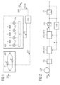
- FIG. 1 shows the series connection of a polarization-dependent adjustable timing element APD and an adjustable optical filter AOF as an essential element for equalization.
- a constant polarization is achieved by a regulated polarization controller (not shown).
- a distorted optical signal OSD is fed to the polarization-dependent delay element APD.
- the signal components are combined again by a COM combiner.
- the adjustable optical filter AOF is designed, for example, as an analog transversal filter, the complex coefficients C1, C2, C3, ... of which can be set.
- analog transversal filter the complex coefficients C1, C2, C3, ... of which can be set.
- IIR filter a feedback filter
- a from the compensated output signal OSI through a splitter SPM branched measurement signal MOSI is a control device CON fed the signal quality of the equalized optical Signals OSI checked.
- the optical signal currently only converted (demodulated) into an electrical signal this also from the optoelectric converter of the receiver can be branched off.
- the setting of the term elements T1 and T2 takes place via a first control signal ST1, which is the Filter coefficients by a second control signal T2.
- the regulation of the delay element and filter can be timed serial, i.e. take place in succession, with several iteration steps to achieve an optimally equalized signal OSI may be necessary. This is useful if the Eye diagrams can be evaluated. However, it can also done simultaneously for runtime element and filter, for example by analyzing the spectrum of the equalized Signal.
- the polarization-dependent delay element can in principle be executed arbitrarily. At the moment seem particularly birefringent Materials, e.g. lithium niobate (LINbO3) to be particularly advantageous.
- the polarization dependent Term element can be first or higher order. Also can have multiple delay elements or optical filters or compensation modules be connected in series according to Figure 1.
- FIG. 2 shows the basic circuit diagram of a series connection of optical compensation modules APD / ADF1 to APD / ADFN, which each contain a series connection of an adjustable timing element APD and an adjustable filter OAF.
- APD optical compensation module
- ADF1 optical compensation module
- APD / ADFN optical compensation module
- APD adjustable timing element
- OAF adjustable filter
- the PDM While in high bit rate optical systems the PDM is channel by channel is to compensate, the compensation of the transit time dispersion and self-phase modulation are carried out, by the optical filter in WDM systems the channel spacing is carried out periodically accordingly.
- PMD compensation occurs channel by channel only after the WDM signal has been divided on individual channels.
- the series connection can also not be adjustable or contain adjustable elements, such as a dispersion-compensating Element DCF, usually a dispersion-compensating Fiber, a dispersion-compensating filter element FID with fixed coefficients (also several fixed ones Filters) that already provide basic compensation.
- a dispersion-compensating Element DCF usually a dispersion-compensating Fiber
- OEC can be used via an optoelectric converter electrical filter EFI of the series circuit described so far downstream for residual compensation. This too can be regulated adaptively.
Landscapes
- Physics & Mathematics (AREA)
- Electromagnetism (AREA)
- Engineering & Computer Science (AREA)
- Computer Networks & Wireless Communication (AREA)
- Signal Processing (AREA)
- Optical Communication System (AREA)
Applications Claiming Priority (2)
| Application Number | Priority Date | Filing Date | Title |
|---|---|---|---|
| DE10147169A DE10147169A1 (de) | 2001-09-25 | 2001-09-25 | Anordnung zur Kompensation von Verzerrungen optischer Signale |
| DE10147169 | 2001-09-25 |
Publications (2)
| Publication Number | Publication Date |
|---|---|
| EP1296472A2 true EP1296472A2 (fr) | 2003-03-26 |
| EP1296472A3 EP1296472A3 (fr) | 2005-12-07 |
Family
ID=7700178
Family Applications (1)
| Application Number | Title | Priority Date | Filing Date |
|---|---|---|---|
| EP02102271A Withdrawn EP1296472A3 (fr) | 2001-09-25 | 2002-09-02 | Dispositif pour la compensation des distorsions de signaux optiques |
Country Status (3)
| Country | Link |
|---|---|
| US (1) | US20030072517A1 (fr) |
| EP (1) | EP1296472A3 (fr) |
| DE (1) | DE10147169A1 (fr) |
Families Citing this family (2)
| Publication number | Priority date | Publication date | Assignee | Title |
|---|---|---|---|---|
| DE10246723A1 (de) * | 2002-10-08 | 2004-05-13 | Siemens Ag | Verfahren und Anordnung zur Ermittlung von Signaldegradationen in Anwesenheit von Signalverzerrungen |
| EP1708390A1 (fr) * | 2005-03-31 | 2006-10-04 | Corning Incorporated | Mitiger l'effet de la distortion d'impulsions le long d'une liaison de communications par fibre optique |
Family Cites Families (10)
| Publication number | Priority date | Publication date | Assignee | Title |
|---|---|---|---|---|
| US5473458A (en) * | 1994-12-27 | 1995-12-05 | At&T Corp. | Soliton data transmission using non-soliton transmitter |
| DE69634021T2 (de) * | 1995-02-24 | 2005-12-15 | Nippon Telegraph And Telephone Corp. | Kohärente Weisslichtquelle und optische Vorrichtungen mit derselben |
| US5822100A (en) * | 1996-06-26 | 1998-10-13 | Mci Communications Corporation | Method and system for equalizing PMD using incremental delay switching |
| US5822476A (en) * | 1997-03-25 | 1998-10-13 | Lucent Technologies Inc. | Time delay device for optical signals |
| US5930414A (en) * | 1997-09-16 | 1999-07-27 | Lucent Technologies Inc. | Method and apparatus for automatic compensation of first-order polarization mode dispersion (PMD) |
| US6289151B1 (en) * | 1998-10-30 | 2001-09-11 | Lucent Technologies Inc. | All-pass optical filters |
| US6801721B1 (en) * | 2000-06-13 | 2004-10-05 | Lucent Technologies Inc. | Polarization mode dispersion compensator for optical fiber communication systems |
| JP4582874B2 (ja) * | 2000-07-13 | 2010-11-17 | 富士通株式会社 | 偏波モード分散補償方法および偏波モード分散補償装置 |
| US6646795B1 (en) * | 2000-11-20 | 2003-11-11 | Nortel Networks Limited | Optical amplifier |
| EP1296471A3 (fr) * | 2001-09-25 | 2005-06-01 | Siemens Aktiengesellschaft | Dispositif de compensation pour égalisation adaptative d'un signal optique |
-
2001
- 2001-09-25 DE DE10147169A patent/DE10147169A1/de not_active Withdrawn
-
2002
- 2002-09-02 EP EP02102271A patent/EP1296472A3/fr not_active Withdrawn
- 2002-09-25 US US10/254,162 patent/US20030072517A1/en not_active Abandoned
Also Published As
| Publication number | Publication date |
|---|---|
| EP1296472A3 (fr) | 2005-12-07 |
| DE10147169A1 (de) | 2003-04-30 |
| US20030072517A1 (en) | 2003-04-17 |
Similar Documents
| Publication | Publication Date | Title |
|---|---|---|
| DE69523106T2 (de) | Vorrichtung und Verfahren zur Kompensation von durch optische Phaserkonjugierung oder andere optische Signalumwandlung verursachter chromatischer Dispersion | |
| DE69834004T2 (de) | Minimierung der Dispersion von faseroptischen Übertragungsstrecken | |
| EP0896445B1 (fr) | Dispositif pour corriger un signal optique déformé par l'interférence optique | |
| DE602004000348T2 (de) | Optischer Mehrkanalentzerrer zur Verminderung der Intersymbolstörung | |
| DE60101252T2 (de) | System eines Diversitätsempfängers zur Verringerung der Faserdispersionseffekte durch die Detektion zweier übertragener Seitenbänder | |
| DE60127762T2 (de) | Polarisationsmodendispersion-Kompensator für ein faseroptisches Übertragungssystem | |
| EP1296471A2 (fr) | Dispositif de compensation pour égalisation adaptative d'un signal optique | |
| DE10246723A1 (de) | Verfahren und Anordnung zur Ermittlung von Signaldegradationen in Anwesenheit von Signalverzerrungen | |
| EP1265382B1 (fr) | Système de transmission optique pour signaux optiques à haut débit avec moyens de compensation de la dispersion | |
| DE602005000871T2 (de) | Verfahren und Vorrichtung zur Dispersionsverwaltung in optischen Nachrichtensystemen | |
| DE10144357C2 (de) | Regelkonzept für einen mehrstufigen Polarisationsmodendispersions-Kompensator | |
| EP1296472A2 (fr) | Dispositif pour la compensation des distorsions de signaux optiques | |
| DE60302786T2 (de) | Verfahren zur optischen Übertragung und optischer Empfänger | |
| DE69733398T2 (de) | Anpassungsvorrichtung für optisches Kommunikationsnetzwerk | |
| DE19602433C2 (de) | Schaltungsanordnung zur Dispersionskompensation in optischen Multiplex-Übertragungssystemen mit Hilfe von dispersionskompensierenden Fasern | |
| EP1188263B1 (fr) | Dispositif de detection de dispersion de polarisation | |
| EP1525684B1 (fr) | Systeme pour transmettre des signaux optiques a differents debits | |
| DE10110853A1 (de) | Dispersionskompensation von optischen Signalverzerrungen höherer Ordnung | |
| EP2080298B1 (fr) | Configuration pour le réglage et la compensation d'une dispersion de modes de polarisation de premier et second ordre | |
| EP1120924A1 (fr) | Procédé d'amélioration de qualité de signaux optiques, système de transmission optique ainsi qu'émetteur | |
| DE60220731T2 (de) | Optisches übertragungssystem unter verwendung einer vorrichtung für optische phasenkonjugation | |
| WO2000003506A1 (fr) | Dispositif permettant de detecter une dispersion de polarisation | |
| DE69822036T2 (de) | Entzerrung, Pulsformung und Regeneration von optischen Signalen | |
| DE602004000164T2 (de) | Vorrichtung und Verfahrung zur Verwaltung der Dispersion in einem optischen Add/Drop Modul | |
| DE19841755A1 (de) | Einrichtung zur Detektion von Polarisationsmodendispersion |
Legal Events
| Date | Code | Title | Description |
|---|---|---|---|
| PUAI | Public reference made under article 153(3) epc to a published international application that has entered the european phase |
Free format text: ORIGINAL CODE: 0009012 |
|
| AK | Designated contracting states |
Kind code of ref document: A2 Designated state(s): AT BE BG CH CY CZ DE DK EE ES FI FR GB GR IE IT LI LU MC NL PT SE SK TR Designated state(s): AT BE BG CH CY CZ DE DK EE ES FI FR GB GR IE IT LI LU MC NL PT SE SK TR |
|
| AX | Request for extension of the european patent |
Extension state: AL LT LV MK RO SI |
|
| PUAL | Search report despatched |
Free format text: ORIGINAL CODE: 0009013 |
|
| AK | Designated contracting states |
Kind code of ref document: A3 Designated state(s): AT BE BG CH CY CZ DE DK EE ES FI FR GB GR IE IT LI LU MC NL PT SE SK TR |
|
| AX | Request for extension of the european patent |
Extension state: AL LT LV MK RO SI |
|
| 17P | Request for examination filed |
Effective date: 20060109 |
|
| STAA | Information on the status of an ep patent application or granted ep patent |
Free format text: STATUS: THE APPLICATION HAS BEEN WITHDRAWN |
|
| 18W | Application withdrawn |
Effective date: 20060524 |