EP1296797B1 - Procede de detection, de localisation et d'identification de defauts dans un cordon de soudure realise par faisceau laser - Google Patents
Procede de detection, de localisation et d'identification de defauts dans un cordon de soudure realise par faisceau laser Download PDFInfo
- Publication number
- EP1296797B1 EP1296797B1 EP01984097A EP01984097A EP1296797B1 EP 1296797 B1 EP1296797 B1 EP 1296797B1 EP 01984097 A EP01984097 A EP 01984097A EP 01984097 A EP01984097 A EP 01984097A EP 1296797 B1 EP1296797 B1 EP 1296797B1
- Authority
- EP
- European Patent Office
- Prior art keywords
- welding
- sensors
- stiffener
- optical
- measurement signals
- Prior art date
- Legal status (The legal status is an assumption and is not a legal conclusion. Google has not performed a legal analysis and makes no representation as to the accuracy of the status listed.)
- Expired - Lifetime
Links
Images


Classifications
-
- B—PERFORMING OPERATIONS; TRANSPORTING
- B23—MACHINE TOOLS; METAL-WORKING NOT OTHERWISE PROVIDED FOR
- B23K—SOLDERING OR UNSOLDERING; WELDING; CLADDING OR PLATING BY SOLDERING OR WELDING; CUTTING BY APPLYING HEAT LOCALLY, e.g. FLAME CUTTING; WORKING BY LASER BEAM
- B23K26/00—Working by laser beam, e.g. welding, cutting or boring
- B23K26/02—Positioning or observing the workpiece, e.g. with respect to the point of impact; Aligning, aiming or focusing the laser beam
- B23K26/03—Observing, e.g. monitoring, the workpiece
- B23K26/032—Observing, e.g. monitoring, the workpiece using optical means
-
- B—PERFORMING OPERATIONS; TRANSPORTING
- B23—MACHINE TOOLS; METAL-WORKING NOT OTHERWISE PROVIDED FOR
- B23K—SOLDERING OR UNSOLDERING; WELDING; CLADDING OR PLATING BY SOLDERING OR WELDING; CUTTING BY APPLYING HEAT LOCALLY, e.g. FLAME CUTTING; WORKING BY LASER BEAM
- B23K1/00—Soldering, e.g. brazing, or unsoldering
- B23K1/005—Soldering by means of radiant energy
- B23K1/0056—Soldering by means of radiant energy soldering by means of beams, e.g. lasers, electron beams [EB]
-
- B—PERFORMING OPERATIONS; TRANSPORTING
- B23—MACHINE TOOLS; METAL-WORKING NOT OTHERWISE PROVIDED FOR
- B23K—SOLDERING OR UNSOLDERING; WELDING; CLADDING OR PLATING BY SOLDERING OR WELDING; CUTTING BY APPLYING HEAT LOCALLY, e.g. FLAME CUTTING; WORKING BY LASER BEAM
- B23K26/00—Working by laser beam, e.g. welding, cutting or boring
- B23K26/20—Bonding
- B23K26/21—Bonding by welding
- B23K26/24—Seam welding
- B23K26/242—Fillet welding, i.e. involving a weld of substantially triangular cross section joining two parts
-
- B—PERFORMING OPERATIONS; TRANSPORTING
- B23—MACHINE TOOLS; METAL-WORKING NOT OTHERWISE PROVIDED FOR
- B23K—SOLDERING OR UNSOLDERING; WELDING; CLADDING OR PLATING BY SOLDERING OR WELDING; CUTTING BY APPLYING HEAT LOCALLY, e.g. FLAME CUTTING; WORKING BY LASER BEAM
- B23K31/00—Processes relevant to this subclass, specially adapted for particular articles or purposes, but not covered by any single one of main groups B23K1/00 - B23K28/00
- B23K31/12—Processes relevant to this subclass, specially adapted for particular articles or purposes, but not covered by any single one of main groups B23K1/00 - B23K28/00 relating to investigating the properties, e.g. the weldability, of materials
- B23K31/125—Weld quality monitoring
Definitions
- the invention relates to a method designed for detect, locate and identify, so destructive and in real time, faults possibly present in weld beads produced by one or more laser beams in accordance with the preamble of claim 1 (see, for example, US-A-5,651,903).
- the invention relates a method for detecting and identifying faults which uses optical sensors sensitive to variations in the light intensity of the plasma that forms in the welding area, under the action of the laser beams.
- the invention applies to the welding of parts any metallic objects such as aluminum alloy, titanium alloy, steel stainless, etc. It can in particular be used to control the edge-to-edge welding of two sheets, the welding of a stiffener on a sheet (T-weld), etc ..
- the invention is adaptable to different welding configurations.
- it relates to all types of welding using one or more lasers, of the YAG, CO 2 type , etc., with or without filler metal.
- Faults likely to be detected and identified by the process according to the invention are internal or external faults considered harmful for the weld bead.
- these defects we will cite as nonlimiting examples the lack weld bead interpenetration in the case of a T-weld, filler wire problems, presence of holes or blisters, the existence of geometric defects, etc.
- monitoring systems for welding used in the automotive industry use bulky sensors, placed in the immediate vicinity of the welding head. Such an arrangement limits the number of sensors and therefore the number of measurement signals available for detection faults.
- the ultraviolet radiation from the plasma produced by the laser beam is detected by a sensor placed at near the welding point and fitted with a filter appropriate.
- the analog signal delivered by the sensor is compared to a threshold and given the value 1 or 0 depending on whether it is above or below this threshold.
- a first optical sensor observes changes in emissions plasma ultraviolet and a second optical sensor measures the temperature variations of the welding downstream of the welding area. We determine then the areas in which variations in signals emitted by these two sensors are maximum and, when these zones are substantially the same, we compare the signals to characteristic values of certain faults, to issue an error signal when a fault is detected. As in the case previous, this system does not detect and above all to reliably distinguish all faults possibly present on the weld bead.
- the subject of the invention is a method to detect and identify, in real time and reliably and reproducibly, defects possibly present in weld beads made by laser.
- this result is obtained by means of a detection process and identification of faults when carrying out a weld bead by at least one laser beam forming a plasma in a welding zone, according to which at least two signals are acquired in real time measurement delivered by separate optical sensors, detecting variations in light intensity of the plasma, characterized in that the signals of measure by applying at least one operator to them mathematical adapted to the detection of a corresponding fault, in order to obtain at least one signal combined, we compare each combined signal to a threshold predetermined, and the presence or the absence of the fault corresponding to each operator mathematical, depending on the result of the comparison.
- the mathematical operator is chosen in the group comprising addition, subtraction, multiplication, division and a combination of these operations.
- a first application of the invention concerns the welding of a stiffener on a sheet by two laser beams placed on either side of the stiffener.
- a sensor When two or more groups are used a sensor, preferably add the signals of measurement delivered by a sensor from each group and detects the presence of a lack of interpenetration of weld seams due to a lack of power laser beams when the result is less than one first predetermined threshold.
- the stiffener and the sheet are positioned beforehand relative to each other by solder points.
- Another application of the invention concerns the edge-to-edge welding of two sheets by one single laser beam.
- the measurement signals are acquired by means of at least a group of three sensors, the sensors of each group detecting emission variations light of the plasma respectively in a band of mainly ultraviolet frequencies, in a band of frequencies mainly visible and in a band mainly infrared frequencies.
- optical sensors each comprising an optical fiber, a first of which end is placed close to the welding area, an optical filter placed in the extension of the second end of the optical fiber and a photodiode placed opposite the second end of the optical fiber, on the other side of the filter.
- the first end of the optical fiber is preferably placed about 10 cm of the welding area.
- thermo sensor detecting variations in thermal energy of the weld bead in back of the welding area.
- the thermal sensor includes another optical fiber whose first end is placed behind the welding area and oriented to the weld bead, and a sensitive photodiode with thermal radiation and placed in the extension from the second end of the other optical fiber.
- an optical focusing means such as a lens is placed at the first end of said optical fiber.
- the first end of said fiber optics is then preferably placed at a distance between about 10 cm and about 20 cm from the welding area. Diameter measurement area included between 1 and 3 mm is preferably placed between 5mm and 5 cm behind the welding area depending on the material welded.
- the measurement signals are combined and compares to said predetermined thresholds after said signals were acquired in real time for the cord welding considered.
- the invention relates to non-destructive testing and in real time of the quality of a weld produced between two pieces 10 and 12 by one or more lasers 14 (illustrated by arrows in Figure 1).
- the part 10 can in particular be a sheet metal substantially flat or slightly curved and part 12 a stiffener that we just weld on the internal face of the sheet 10 by means of two laser beams 14 located on either side of the stiffener 12.
- the invention applies however to other types of assembly such that the edge-to-edge assembly of two sheets, etc.
- exhibits 10 and 12 the welding must be checked are metal parts which can be made of different metals such than aluminum alloys, titanium alloys, stainless steels, etc.
- the laser (s) 14 used to weld between them pieces 10 and 12 can be made by all types of lasers usually used in industry to weld the affected materials.
- the pieces 10 and 12 that one desires assemble by welding are generally positioned beforehand with respect to each other by solder points (not shown).
- the welding of parts 10 and 12 is carried out by a welding machine (not shown) which incorporates a welding head located near the parts 10 and 12 to be welded, and means for ensuring a relative displacement between said welding head and the parts according to a predetermined welding line.
- a welding machine (not shown) which incorporates a welding head located near the parts 10 and 12 to be welded, and means for ensuring a relative displacement between said welding head and the parts according to a predetermined welding line.
- the welding head includes in particular optical systems for directing the laser beams on the welding area, one or more filler metal feeders required welding and one or more nozzles through which a neutral gas such as argon or helium is brought into the welding area.
- the welding machine a control or monitoring system solder, to detect, locate and identify in real time, i.e. during passage of the welding head, possible defects in the welding performed.
- control system includes seven optical sensors C1 to C7, as well as means 10 for acquisition and processing of the measurement signals delivered by each of these sensors.
- the number of optical sensors used can however be different from seven and made up of any number greater than or equal to two, without departing from the scope of the invention.
- Sensors C1 to C6 are so-called sensors “plasma sensors”, which detect variations light intensity of the plasma formed by the beams laser 14, in the welding area. To this end, each of sensors C1 to C6 is mounted on the welding head and oriented towards the point of impact of the laser beams on parts 10 and 12.
- Each of the plasma sensors C1 to C6 includes respectively an optical fiber 16-1 to 16-6 including one first end is located near the area of welding and oriented towards said zone, that is to say towards the point of impact of the laser beams 14 on the parts 10 and 12. More specifically, the optical fibers 16-1 to 16-3 are located on one side of the stiffener 12 and oriented towards the plasma formed by the laser beam 14 directed towards this same side, while the optical fibers 16-4 to 16-6 are located on the other side of the stiffener 12 and oriented towards the plasma formed by the beam laser 14 directed towards this other side. In order to avoid splashes of molten metal and high heat cleared during welding, the first end of each of the optical fibers 16-1 to 16-6 is placed at about 10 cm from the weld area.
- the optical fibers 16-1 to 16-6 are, for example, PMMA index hopping fibers. This kind of fiber has the particular advantage of presenting a large numerical aperture allowing to observe the whole plasma, as well as good transmission for the observed wavelengths.
- Each of the sensors C1 to C6 includes plus a respective optical filter 18-1 to 18-6, placed in the extension of the opposite end of the fiber corresponding optics.
- the filters optics 18-1 and 18-4 of sensors C1 and C4 leave mainly pass a frequency band corresponding to ultraviolet radiation
- the filters 18-2 and 18-5 of sensors C2 and C5 let through mainly a frequency band corresponding to visible radiation
- filters 18-3 and 18-6 mainly pass a frequency band corresponding to infrared radiation.
- Each of the sensors C1 to C6 includes addition, respectively, a photodiode 20-1 to 20-6 placed opposite the second end of the fiber corresponding optics, on the other side of the filter.
- the photodiodes transform the optical signals they receive electrical signals. These last signals constitute the measurement signals delivered by the sensors C1 to C6.
- Photodiodes 20-1 to 20-6 are, for example, sensitive silicon photodiodes in the area ranging from 0.3 to 1.1 ⁇ m.
- optical fibers 16-1 to 16-6 allows have a high number of sensors, while minimizing the size of the control near the welding area. Indeed, relatively large items such as filters and photodiodes can be installed in outside this area.
- This arrangement also makes it possible to acquire measurement signals representing a large number of different sizes (six in the example described), this which contributes to increasing the information allowing detect and distinguish possible faults one another.
- the optional seventh optical sensor C7 is a so-called "thermal” sensor which detects variations in thermal energy of the weld bead in back of the welding area, i.e. back of the point of impact of the laser beams 14 on the parts 10 and 12.
- the thermal sensor C7 also includes an optical fiber 16-7.
- a first end of this optical fiber 16-7 is oriented towards the weld bead S formed behind the area of welding, on one side of the stiffener 12. More precisely, the first end of fiber optic 16-7 is oriented towards a point of the weld bead S located at a distance L between approximately 5 mm and approximately 1 cm in back of the welding area. Indeed, the others measuring point positions do not allow obtain exploitable signals.
- the end of the optical fiber 16-7 facing the weld bead S is equipped with a focusing means 22-7, such as a lens 20 mm focal length, to limit the area of observation of sensor C7 at a circle of 1 to 3 mm from diameter approximately, and place the end of the fiber equipped with its focusing system between 10 and 20 cm from the welding area.
- a focusing means 22-7 such as a lens 20 mm focal length
- the optical fiber 16-7 is a fiber in silica with low attenuation in the near infrared (between 1 and 1.8 ⁇ m).
- a 20-7 photodiode is placed opposite the opposite end of the fiber optics 16-7. This 20-7 photodiode transforms optical signals carried by optical fiber 16-7 in electrical signals, which also constitute measurement signals according to the invention.
- the spectral response of photodiode 20-7 varies, by example, between 0.8 and 1.8 ⁇ m.
- a filter 18-7 optic is also interposed between the fiber optics 16-7 and photodiode 20-7, to block the radiation of wavelength less than 1 ⁇ m, so the C7 sensor does not see the light emitted by the plasma.
- An electronic band pass filter (no shown) is placed at the exit of each of photodiodes 20-1 to 20-7, in order to suppress possible noise in the processed signals.
- the measurement signals delivered by each sensors C1 to C7 are transmitted to means 10 acquisition and processing.
- These means which include a computer, can be located in any location, near or not near the welding head.
- the means 10 for acquiring and processing measurement signals successively carry out a certain number of operations which will now be described in detail.
- a first step E1 which takes place simultaneously with the production of the cords of welding S by the laser beams 14, we record the seven measurement signals delivered by the C1 sensors to C7.
- a second step, illustrated in E2 on the Figure 3, is implemented when the cords of S welds are complete.
- a step E3 it is verified that it there is no unacceptable drift of the control.
- the overall average value of each of the measurement signals which has just been calculated, is compared to the overall average values of these signals recorded during a number of corresponding measurements previously made. AT as an example, we compare the last five values recorded. When this comparison reveals a drift greater than a predetermined threshold (for example, 30%), the operator is alerted by the trigger an alarm. This alarm can take a form any (visual, audible, etc.).
- each of the seven signals is standardized. This is done by dividing the instantaneous value of each signal by the average value of this signal calculated in step E2. The standard deviation is then determined for each of the measurement signals, from standardized signals.
- step E5 it is verified that the value of the standard deviation of each measurement signal which has just been calculated does not exceed a threshold predetermined specific to this signal. If this threshold is exceeded, the operator is informed by the emission of a alarm in any suitable form (sound, visual, etc.). Indeed, exceeding this threshold reveals a quality of weld that varies so excessive over its entire length.
- the program then proceeds to a step E6, essential according to the invention, during which the different standardized measurement signals are processed from in order to detect, locate and identify various faults possibly present in the welding which has just been carried out.
- step E6 we apply to the minus a simple mathematical operator to one or several groups of at least two measurement signals standardized, so as to obtain one or more signals combined.
- Each operator and group of signals to which it is applied are specific to the detection of a particular type of fault, as illustrated in examples which will be described later.
- Each combined signal obtained by the application of a particular operator is then compared, in E7, to a predetermined threshold, which depends also of the operator and, therefore, of the type of fault to be detected.
- a predetermined threshold which depends also of the operator and, therefore, of the type of fault to be detected.
- the operator is informed of the occurrence of an anomaly, the location of the defect and the nature of it.
- This information can be provided by a means any such as a visual, audible or other alarm, a display, etc.
- the results obtained by applying these different treatments are finally edited under the form of a summary report as indicated in E8 on Figure 3.
- the summary report indicates in particular whether soldering is acceptable or not, if some settings must be changed on the machine welding, etc.
- a first treatment we add standard measurement signals derived from sensors C1 and C4 or sensors C2 and C5. The operator is therefore a simple addition. We then compare the signal handset obtained at a predetermined threshold. If the sum previously calculated is below this threshold on a at least part of the length of the weld beads S, this means that there is a lack in this area of interpenetration of these weld beads and that this fault is caused by a lack of power laser beams. This information is then brought to operator knowledge in a form any appropriate.
- FIG. 4A is a curve obtained during of a trial, applying this first treatment on the base of standardized measurement signals from sensors C1 and C4.
- absc issa the distance (in mm) traveled along the weld bead and ordinate the combined signal SC1 corresponding to the sum of the measurement signals standardized from sensors C1 and C4.
- this combined signal SC1 becomes below the lower threshold SI1 in the part of the weld beads located between 900 mm and 1350 mm.
- interpenetration cords are insufficient in this area, due a lack of power of the laser beams.
- a mathematical operator which adds on the one hand, the signals from sensors C1 and C4 and secondly, the signals from sensors C2 and C5, then multiply one by the other the two sums.
- the combined signal obtained by applying this operator is then compared to a second predetermined threshold. If this threshold is exceeded, we deduce that there is a lack of interpenetration of the two weld beads S due to a problem other than the lack of power of laser beams. This other problem can be, for for example, a lack of filler metal. As in the case previous, the corresponding information is brought to the knowledge of the user.
- a third treatment apply to standardized measurement signals from C1 sensors and C4 an operator constituted by a division.
- the combined signal as well obtained is then compared to a third threshold superior. If the comparison reveals that the signal combined exceeds this third threshold, we deduce that the "pointing" of the parts is deficient. information is brought to the attention of the user in any suitable form.
- the same fault can be detected by applying an operator comparable to the previous one, in which the two sums are replaced by two multiplications. We then compare the combined signal obtained by dividing the results of these two multiplications with another lower threshold predetermined.
- the invention also applies to other types of welding.
- it can also be used in the case of edge-to-edge welding of two sheets with a single beam laser.
- At least two plasma sensors which detect variations in the light intensity of the plasma in different optical bands. Measuring signals standardized from these sensors can then be divided by each other to provide a signal combined, which is then compared to a lower threshold predetermined and / or at a predetermined upper threshold.
- the combined signal is less than lower threshold, we deduce that the weld bead has a recessed part in the area concerned.
- the combined signal is greater than upper threshold, we deduce that the weld bead is incomplete.
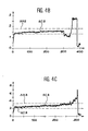
- FIGS. 4B and 4C illustrate the results of tests carried out respectively during the edge-to-edge welding of two sheets of stainless steel and during the edge-to-edge welding of two sheets of titanium alloy. In both cases, the welding was carried out by a CO 2 laser. As in FIG. 4A, the distance (in mm) along the weld bead has been plotted on the abscissa and the value of the signal ratio corresponding to the combined signal has been plotted on the ordinate.
- the signal SC2 handset is below the lower threshold predetermined between 301 mm and 340 mm and greater than SS2 predetermined upper threshold from 340 mm to 392 mm.
- the weld bead has a part recessed in the first zone and an unwelded part in the second zone.
- the signal handset SC3 exceeds the predetermined upper threshold SS3 in the part of the weld bead corresponding to a distance greater than 270 mm. We deduce that the weld bead is incomplete in this area.
- the mathematical operator used according to the invention is an operator simple consisting of an addition, a subtraction, a multiplication, a division or a combination any of these different operations.
- the number of sensors used can also be a number any, greater than or equal to two.
Landscapes
- Engineering & Computer Science (AREA)
- Physics & Mathematics (AREA)
- Optics & Photonics (AREA)
- Mechanical Engineering (AREA)
- Plasma & Fusion (AREA)
- Quality & Reliability (AREA)
- Laser Beam Processing (AREA)
- Investigating Materials By The Use Of Optical Means Adapted For Particular Applications (AREA)
Description
- la figure 1 est une vue en perspective qui représente schématiquement un appareil de soudage laser utilisé pour le soudage d'un raidisseur sur une tôle et équipé d'un système de détection et d'identification de défauts mettant en oeuvre le procédé selon l'invention ;
- la figure 2 est une vue de côté, illustrant schématiquement la position du capteur thermique par rapport à celle des capteurs plasma ;
- la figure 3 est un organigramme expliquant les différentes étapes du traitement des signaux de mesure dans le système de détection et d'identification de défauts de la figure 1 ;
- les figures 4A à 4C sont des courbes qui illustrent, dans trois applications particulières, la comparaison de signaux de mesure combinés à des valeurs de seuil prédéterminées, effectuée conformément à l'invention.
Claims (17)
- Procédé de détection, de localisation et d'identification de défauts lors de la réalisation d'un cordon de soudure (S) par au moins un faisceau laser (14) formant un plasma dans une zone de soudage, selon lequel on acquiert en temps réel au moins deux signaux de mesure délivrés par des capteurs optiques (C1-C6) distincts, détectant des variations d'intensité lumineuse du plasma, caractérisé en ce qu'on combine, pour chacun des défauts à détecter, localiser et à identifier, les au moins deux signaux de mesure délivrés par les capteurs optiques (C1-C6) en leur appliquant au moins un opérateur mathématique adapté à la détection d'un défaut correspondant, afin d'obtenir au moins un signal combiné, on compare chaque signal combiné à un seuil prédéterminé associé au défaut correspondant, et on diagnostique la présence ou l'absence du défaut correspondant à chaque opérateur mathématique, selon le résultat de la comparaison.
- Procédé selon la revendication 1, dans lequel l'opérateur mathématique est choisi dans le groupe comprenant l'addition, la soustraction, la multiplication, la division et une combinaison de celles-ci.
- Procédé selon la revendication 2, appliqué à la soudure d'un raidisseur (12) sur une tôle (10) par deux faisceaux laser (14) placés de part et d'autre du raidisseur, dans lequel on utilise deux groupes d'au moins un capteur optique (C1,C2,C3;C4,C5,C6) disposés de part et d'autre du raidisseur, les capteurs optiques des deux groupes étant identiques, on additionne les signaux de mesure délivrés par un capteur de chaque groupe et on détecte la présence d'un manque d'interpénétration des cordons de soudure dû à un manque de puissance des faisceaux laser lorsque le résultat est inférieur à un premier seuil prédéterminé.
- Procédé selon l'une quelconque des revendications 2 et 3, appliqué à la soudure d'un raidisseur (12) sur une tôle (10) par deux faisceaux laser (14) placés de part et d'autre du raidisseur, dans lequel on utilise deux groupes d'au moins deux capteurs optiques (C1,C2,C3 ;C4,C5,C6) détectant des variations d'intensité lumineuse du plasma dans des bandes optiques différentes, disposés de part et d'autre du raidisseur, les capteurs optiques des deux groupes étant identiques, on additionne d'une part les signaux de mesure délivrés par une première paire de capteurs identiques et d'autre part les signaux de mesure délivrés par une deuxième paire de capteurs identiques, on multiplie l'une par l'autre les deux sommes obtenues et on détecte un manque d'interpénétration des cordons de soudure, dû à un défaut autre qu'un manque de puissance des faisceaux laser, lorsque le résultat est supérieur à un deuxième seuil prédéterminé.
- Procédé selon l'une quelconque des revendications 2 à 4, appliqué à la soudure d'un raidisseur (12) sur une tôle (10) par deux faisceaux laser (14) placés de part et d'autre du raidisseur, le raidisseur et la tôle étant positionnés au préalable l'un par rapport à l'autre par des points de soudure, dans lequel on utilise deux groupes d'au moins un capteur optique (C1,C2,C3;C4,C5,C6) disposés de part et d'autre du raidisseur, les capteurs optiques des deux groupes étant identiques, on divise l'un par l'autre les signaux de mesure délivrés par deux capteurs identiques et on détecte la présence de points de soudure de positionnement préalable déficients lorsque le résultat est supérieur à un troisième seuil prédéterminé.
- Procédé selon l'une quelconque des revendications 2 à 5, appliqué à la soudure d'un raidisseur (12) sur une tôle (10) par deux faisceaux laser (14) placés de part et d'autre du raidisseur, dans lequel on utilise deux groupes d'au moins deux capteurs optiques (C1,C2,C3;C4,C5,C6) détectant des variations d'intensité lumineuse du plasma dans des bandes optiques différentes, disposés de part et d'autre du raidisseur, les capteurs optiques des deux groupes étant identiques, on additionne d'une part les signaux de mesure délivrés par une première paire de capteurs identiques et d'autre part les signaux de mesure délivrés par une deuxième paire de capteurs identiques, on divise l'une par l'autre les deux sommes obtenues, et on détecte une largeur insuffisante du cordon de soudure lorsque le résultat de la division est inférieur à un quatrième seuil prédéterminé.
- Procédé selon l'une quelconque des revendications 1 et 2, appliqué à la soudure bord à bord de deux tôles par un seul faisceau laser, dans lequel on utilise au moins deux capteurs optiques détectant des variations d'intensité lumineuse du plasma dans des bandes optiques différentes, on divise l'un par l'autre les signaux de mesure délivrés par deux des capteurs et on détecte un manque d'épaisseur du cordon de soudure lorsque le résultat obtenu est inférieur à un premier seuil et une absence de soudage lorsque le résultat est supérieur à un deuxième seuil, supérieur au premier.
- Procédé selon l'une quelconque des revendications précédentes, dans lequel on acquiert les signaux de mesure au moyen d'au moins un groupe de trois capteurs (C1,C2,C3;C4,C5,C6), les capteurs de chaque groupe détectant les variations d'émission lumineuse du plasma respectivement dans une bande de fréquences principalement ultraviolette, dans une bande de fréquences principalement visible et dans une bande de fréquences principalement infrarouge.
- Procédé selon l'une quelconque des revendications précédentes, dans lequel on utilise des capteurs optiques (C1,C2,C3;C4,C5,C6)comprenant chacun une fibre optique (16-1 à 16-6) dont une première extrémité est placée à proximité de la zone de soudage, un filtre optique (18-1 à 18-6) placé dans le prolongement de la deuxième extrémité de la fibre optique et une photodiode (20-1 à 20-6) placée en face de la deuxième extrémité de la fibre optique, de l'autre côté du filtre.
- Procédé selon la revendication 9, dans lequel la première extrémité de la fibre optique est placée à environ 10 cm de la zone de soudage.
- Procédé selon l'une quelconque des revendications précédentes, dans lequel on acquiert un signal de mesure supplémentaire au moyen d'un autre capteur optique (C7), détectant des variations d'énergie thermique du cordon de soudure en arrière de la zone de soudage.
- Procédé selon la revendication 11, dans lequel l'autre capteur optique (C7) comprend une autre fibre optique (16-7) dont une première extrémité est placée en arrière de la zone de soudage et orientée vers le cordon de soudure, et une photodiode (20-7) sensible au rayonnement thermique et placée dans le prolongement de la deuxième extrémité de l'autre fibre optique.
- Procédé selon la revendication 12, dans lequel la première extrémité de l'autre fibre optique (16-7) est placée à une distance comprise entre environ 10 cm et environ 20 cm, de la zone de soudage.
- Procédé selon l'une quelconque des revendications 12 et 13, dans lequel un moyen optique de focalisation (22-7) est placé à la première extrémité de l'autre fibre optique (16-7).
- Procédé selon l'une quelconque des revendications précédentes, dans lequel on combine les signaux de mesure et on les compare auxdits seuils prédéterminés après que lesdits signaux aient été acquis en temps réel pour le cordon de soudage considéré.
- Procédé selon la revendication 15, dans lequel on calcule la valeur moyenne, la valeur moyenne normalisée, puis l'écart type de chaque signal de mesure, et on diagnostique une qualité irrégulière de la soudure lorsque l'écart type dépasse une valeur prédéterminée.
- Procédé selon la revendication 16, dans lequel on compare la valeur moyenne de chaque signal de mesure aux valeurs moyennes précédentes dudit signal, enregistrées pour un nombre donné de cordons de soudure contrôlés auparavant et on diagnostique une dérive de l'appareil de mesure lorsque la valeur moyenne du signal a varié d'environ 30%, au moins, par rapport aux valeurs moyennes précédentes.
Applications Claiming Priority (3)
| Application Number | Priority Date | Filing Date | Title |
|---|---|---|---|
| FR0008798 | 2000-07-06 | ||
| FR0008798A FR2811427B1 (fr) | 2000-07-06 | 2000-07-06 | Procede de detection et d'identification de defauts dans un cordon de soudure realise par faisceau laser |
| PCT/FR2001/002157 WO2002002268A1 (fr) | 2000-07-06 | 2001-07-05 | Procede de detection et d'identification de defauts dans un cordon de soudure realise par faisceau laser |
Publications (2)
| Publication Number | Publication Date |
|---|---|
| EP1296797A1 EP1296797A1 (fr) | 2003-04-02 |
| EP1296797B1 true EP1296797B1 (fr) | 2004-10-13 |
Family
ID=8852176
Family Applications (1)
| Application Number | Title | Priority Date | Filing Date |
|---|---|---|---|
| EP01984097A Expired - Lifetime EP1296797B1 (fr) | 2000-07-06 | 2001-07-05 | Procede de detection, de localisation et d'identification de defauts dans un cordon de soudure realise par faisceau laser |
Country Status (7)
| Country | Link |
|---|---|
| US (1) | US6937329B2 (fr) |
| EP (1) | EP1296797B1 (fr) |
| AU (1) | AU2002216755A1 (fr) |
| CA (1) | CA2413930C (fr) |
| DE (1) | DE60106444T2 (fr) |
| FR (1) | FR2811427B1 (fr) |
| WO (1) | WO2002002268A1 (fr) |
Families Citing this family (82)
| Publication number | Priority date | Publication date | Assignee | Title |
|---|---|---|---|---|
| JP4531396B2 (ja) * | 2001-11-15 | 2010-08-25 | プレシテック ヴィジョン ゲゼルシャフト ミット ベシュレンクテル ハフツング ウント コンパニー コマンディートゲゼルシャフト | ワークの接合箇所を評価するための方法および装置 |
| JP3792683B2 (ja) * | 2003-07-16 | 2006-07-05 | ファナック株式会社 | レーザ溶接装置 |
| ES2255396B1 (es) * | 2004-07-08 | 2007-06-16 | Centro De Automatizaciono, Robotica Y Tecnologias De La Informacion Y La Fabricacion | Instalacion y metodo de control de calidad de cordones de soldadura laser en procesos automatizados. |
| DE102005027342A1 (de) * | 2005-06-13 | 2006-12-14 | Abb Research Ltd. | Fehlersuchsystem zum Erkennen von Fehlerstellen an Schweißnähten |
| KR100797239B1 (ko) * | 2005-12-23 | 2008-01-23 | 주식회사 포스코 | 강판의 용접부 온라인 검출장치 및 방법 |
| US9352411B2 (en) | 2008-05-28 | 2016-05-31 | Illinois Tool Works Inc. | Welding training system |
| US8297122B2 (en) * | 2009-06-19 | 2012-10-30 | Georgia Tech Research Corporation | Methods and systems for detecting defects in welded structures |
| US8146429B2 (en) * | 2009-08-03 | 2012-04-03 | Georgia Tech Research Corporation | Methods and systems for classifying the type and severity of defects in welds |
| US8256296B2 (en) * | 2009-08-03 | 2012-09-04 | Georgia Tech Research Corporation | Methods and systems for detecting defects in welded structures utilizing pattern matching |
| JP4911232B2 (ja) * | 2010-02-25 | 2012-04-04 | トヨタ自動車株式会社 | ビード検査方法及びビード検査装置 |
| IT1401726B1 (it) * | 2010-08-31 | 2013-08-02 | Consiglio Nazionale Ricerche | Metodo per l'individuazione di difettosita' nel processo di saldatura laser continua di parti metalliche. |
| KR101240980B1 (ko) * | 2010-11-18 | 2013-03-11 | 기아자동차주식회사 | 레이저 용접 품질 검사 방법 및 장치 |
| EP2497581B1 (fr) * | 2011-03-11 | 2022-09-21 | Steel-Invest Ltd | Rail-poutre en acier pour un train magnétique, et méthode et système de fabrication d'un tel rail-poutre |
| US9101994B2 (en) | 2011-08-10 | 2015-08-11 | Illinois Tool Works Inc. | System and device for welding training |
| JP5789527B2 (ja) * | 2012-01-18 | 2015-10-07 | 株式会社アマダホールディングス | レーザ加工装置及びレーザ発振制御方法 |
| US9573215B2 (en) | 2012-02-10 | 2017-02-21 | Illinois Tool Works Inc. | Sound-based weld travel speed sensing system and method |
| US9583014B2 (en) | 2012-11-09 | 2017-02-28 | Illinois Tool Works Inc. | System and device for welding training |
| US9368045B2 (en) | 2012-11-09 | 2016-06-14 | Illinois Tool Works Inc. | System and device for welding training |
| CH707367A8 (de) * | 2012-12-18 | 2014-12-15 | Micromachining Ag | Verfahren zum Bearbeiten einer Folge von Werkstücken mittels mindestens eines Bearbeitungsstrahls. |
| US9666100B2 (en) | 2013-03-15 | 2017-05-30 | Illinois Tool Works Inc. | Calibration devices for a welding training system |
| US9713852B2 (en) | 2013-03-15 | 2017-07-25 | Illinois Tool Works Inc. | Welding training systems and devices |
| US9728103B2 (en) | 2013-03-15 | 2017-08-08 | Illinois Tool Works Inc. | Data storage and analysis for a welding training system |
| US9583023B2 (en) | 2013-03-15 | 2017-02-28 | Illinois Tool Works Inc. | Welding torch for a welding training system |
| US9672757B2 (en) | 2013-03-15 | 2017-06-06 | Illinois Tool Works Inc. | Multi-mode software and method for a welding training system |
| JP5947741B2 (ja) * | 2013-03-29 | 2016-07-06 | トヨタ自動車株式会社 | 溶接部の検査装置とその検査方法 |
| JP5947740B2 (ja) | 2013-03-29 | 2016-07-06 | トヨタ自動車株式会社 | 溶接部の検査装置とその検査方法 |
| JP5849985B2 (ja) * | 2013-04-15 | 2016-02-03 | トヨタ自動車株式会社 | 溶接部の検査装置とその検査方法 |
| US10480862B2 (en) | 2013-05-23 | 2019-11-19 | Crc-Evans Pipeline International, Inc. | Systems and methods for use in welding pipe segments of a pipeline |
| US10589371B2 (en) | 2013-05-23 | 2020-03-17 | Crc-Evans Pipeline International, Inc. | Rotating welding system and methods |
| US10040141B2 (en) | 2013-05-23 | 2018-08-07 | Crc-Evans Pipeline International, Inc. | Laser controlled internal welding machine for a pipeline |
| US10695876B2 (en) | 2013-05-23 | 2020-06-30 | Crc-Evans Pipeline International, Inc. | Self-powered welding systems and methods |
| US11767934B2 (en) | 2013-05-23 | 2023-09-26 | Crc-Evans Pipeline International, Inc. | Internally welded pipes |
| US9821415B2 (en) * | 2014-03-28 | 2017-11-21 | Crc-Evans Pipeline International, Inc. | Internal pipeline cooler |
| US11090753B2 (en) | 2013-06-21 | 2021-08-17 | Illinois Tool Works Inc. | System and method for determining weld travel speed |
| JP5967042B2 (ja) * | 2013-09-12 | 2016-08-10 | Jfeスチール株式会社 | レーザ溶接良否判定装置及びレーザ溶接良否判定方法 |
| US9314878B2 (en) * | 2013-09-12 | 2016-04-19 | Ford Global Technologies, Llc | Non-destructive aluminum weld quality estimator |
| US10056010B2 (en) | 2013-12-03 | 2018-08-21 | Illinois Tool Works Inc. | Systems and methods for a weld training system |
| US9751149B2 (en) | 2014-01-07 | 2017-09-05 | Illinois Tool Works Inc. | Welding stand for a welding system |
| US10105782B2 (en) | 2014-01-07 | 2018-10-23 | Illinois Tool Works Inc. | Feedback from a welding torch of a welding system |
| US9724788B2 (en) | 2014-01-07 | 2017-08-08 | Illinois Tool Works Inc. | Electrical assemblies for a welding system |
| US10170019B2 (en) | 2014-01-07 | 2019-01-01 | Illinois Tool Works Inc. | Feedback from a welding torch of a welding system |
| US9589481B2 (en) | 2014-01-07 | 2017-03-07 | Illinois Tool Works Inc. | Welding software for detection and control of devices and for analysis of data |
| US9757819B2 (en) | 2014-01-07 | 2017-09-12 | Illinois Tool Works Inc. | Calibration tool and method for a welding system |
| US9937578B2 (en) | 2014-06-27 | 2018-04-10 | Illinois Tool Works Inc. | System and method for remote welding training |
| US10307853B2 (en) | 2014-06-27 | 2019-06-04 | Illinois Tool Works Inc. | System and method for managing welding data |
| US10665128B2 (en) | 2014-06-27 | 2020-05-26 | Illinois Tool Works Inc. | System and method of monitoring welding information |
| US9862049B2 (en) | 2014-06-27 | 2018-01-09 | Illinois Tool Works Inc. | System and method of welding system operator identification |
| US9724787B2 (en) | 2014-08-07 | 2017-08-08 | Illinois Tool Works Inc. | System and method of monitoring a welding environment |
| US11014183B2 (en) | 2014-08-07 | 2021-05-25 | Illinois Tool Works Inc. | System and method of marking a welding workpiece |
| US9875665B2 (en) | 2014-08-18 | 2018-01-23 | Illinois Tool Works Inc. | Weld training system and method |
| AU2015308646A1 (en) | 2014-08-29 | 2017-02-09 | Crc-Evans Pipeline International Inc. | Method and system for welding |
| US10239147B2 (en) | 2014-10-16 | 2019-03-26 | Illinois Tool Works Inc. | Sensor-based power controls for a welding system |
| US11247289B2 (en) | 2014-10-16 | 2022-02-15 | Illinois Tool Works Inc. | Remote power supply parameter adjustment |
| US10204406B2 (en) | 2014-11-05 | 2019-02-12 | Illinois Tool Works Inc. | System and method of controlling welding system camera exposure and marker illumination |
| US10402959B2 (en) | 2014-11-05 | 2019-09-03 | Illinois Tool Works Inc. | System and method of active torch marker control |
| US10373304B2 (en) | 2014-11-05 | 2019-08-06 | Illinois Tool Works Inc. | System and method of arranging welding device markers |
| US10490098B2 (en) | 2014-11-05 | 2019-11-26 | Illinois Tool Works Inc. | System and method of recording multi-run data |
| US10210773B2 (en) | 2014-11-05 | 2019-02-19 | Illinois Tool Works Inc. | System and method for welding torch display |
| US10417934B2 (en) | 2014-11-05 | 2019-09-17 | Illinois Tool Works Inc. | System and method of reviewing weld data |
| US10427239B2 (en) | 2015-04-02 | 2019-10-01 | Illinois Tool Works Inc. | Systems and methods for tracking weld training arc parameters |
| US10593230B2 (en) | 2015-08-12 | 2020-03-17 | Illinois Tool Works Inc. | Stick welding electrode holder systems and methods |
| US10438505B2 (en) | 2015-08-12 | 2019-10-08 | Illinois Tool Works | Welding training system interface |
| US10657839B2 (en) | 2015-08-12 | 2020-05-19 | Illinois Tool Works Inc. | Stick welding electrode holders with real-time feedback features |
| US10373517B2 (en) | 2015-08-12 | 2019-08-06 | Illinois Tool Works Inc. | Simulation stick welding electrode holder systems and methods |
| JP2017177222A (ja) * | 2016-03-28 | 2017-10-05 | パナソニックIpマネジメント株式会社 | レーザ溶接方法およびレーザ溶接装置 |
| US11458571B2 (en) | 2016-07-01 | 2022-10-04 | Crc-Evans Pipeline International, Inc. | Systems and methods for use in welding pipe segments of a pipeline |
| DE102016217758B3 (de) * | 2016-09-16 | 2018-01-25 | Technische Universität Dresden | Verfahren und Vorrichtung zur Prozessüberwachung bei einer mittels Kollisionsschweißen gebildeten Schweißnaht |
| JP6363680B2 (ja) * | 2016-11-16 | 2018-07-25 | ファナック株式会社 | レーザ装置 |
| CN108375581B (zh) * | 2017-01-04 | 2020-08-04 | 中国航空制造技术研究院 | 基于声光信号监测的双光束激光焊接过程缺陷控制方法 |
| WO2019244484A1 (fr) * | 2018-06-22 | 2019-12-26 | 三菱電機株式会社 | Dispositif de traitement au laser |
| JP7152277B2 (ja) * | 2018-11-27 | 2022-10-12 | トヨタ自動車株式会社 | 溶接検査装置 |
| US11776423B2 (en) | 2019-07-22 | 2023-10-03 | Illinois Tool Works Inc. | Connection boxes for gas tungsten arc welding training systems |
| US11288978B2 (en) | 2019-07-22 | 2022-03-29 | Illinois Tool Works Inc. | Gas tungsten arc welding training systems |
| TWI717106B (zh) | 2019-11-18 | 2021-01-21 | 財團法人工業技術研究院 | 銲接品質檢測系統與方法 |
| FR3116744B1 (fr) * | 2020-11-27 | 2023-10-20 | Soc Dassemblages Par Faisceaux Delectrons Et Laser | Machine laser et procédé de fabrication à détection de seuils de plasma |
| DE102021103881A1 (de) * | 2021-02-18 | 2022-08-18 | Precitec Gmbh & Co. Kg | Verfahren und Laserbearbeitungssystem zum Analysieren einer durch einen Laserschweißprozess ausgebildeten Schweißnaht |
| CN113076817B (zh) * | 2021-03-17 | 2022-11-04 | 上海展湾信息科技有限公司 | 焊缝气孔缺陷实时检测方法及系统 |
| DE102021107544B4 (de) * | 2021-03-25 | 2023-01-05 | Precitec Gmbh & Co. Kg | Verfahren zur Normierung von Sensorsignalen für die Überwachung eines Laserbearbeitungsprozesses, Verfahren zum Überwachen eines Laserbeitungsprozesses und Laserbearbeitungssystem |
| JP7591750B2 (ja) * | 2021-06-07 | 2024-11-29 | パナソニックIpマネジメント株式会社 | レーザ加工方法及びレーザ加工装置 |
| CN115824400A (zh) * | 2022-07-01 | 2023-03-21 | 宁德时代新能源科技股份有限公司 | 激光功率检测系统、焊接系统和激光焊接工件的检测方法 |
| CN115592309A (zh) * | 2022-10-26 | 2023-01-13 | 重庆川仪自动化股份有限公司(Cn) | 一种焊接方法、装置、设备及介质 |
| CN119737862B (zh) * | 2024-11-06 | 2025-07-22 | 无锡华立聚能装备有限公司 | Tc4材料的深海扁平作动器进出油口焊缝检测装置及方法 |
Family Cites Families (12)
| Publication number | Priority date | Publication date | Assignee | Title |
|---|---|---|---|---|
| US3712736A (en) * | 1971-01-05 | 1973-01-23 | Commissariat Energie Atomique | Method and device for testing welds by optical spectrography |
| DE3908187A1 (de) * | 1989-03-14 | 1990-09-20 | Jurca Marius Christian | Verfahren zur qualitaetssicherung beim laserstrahlschweissen und -schneiden |
| DE4002627A1 (de) | 1990-01-30 | 1991-08-08 | Deutsche Forsch Luft Raumfahrt | Schweissueberwachungseinrichtung |
| DE4106007A1 (de) * | 1991-02-26 | 1992-09-03 | Fraunhofer Ges Forschung | Verfahren und vorrichtung zum bearbeiten von werkstuecken mit laserstrahlung |
| US5245409A (en) * | 1991-11-27 | 1993-09-14 | Arvin Industries, Inc. | Tube seam weld inspection device |
| US5651903A (en) * | 1995-10-12 | 1997-07-29 | Trw Inc. | Method and apparatus for evaluating laser welding |
| JPH1085967A (ja) * | 1996-09-20 | 1998-04-07 | Matsushita Electric Ind Co Ltd | レーザ誘起プラズマ検出方法とそれを用いるレーザ制御方法およびレーザ加工機 |
| DE19639667C1 (de) * | 1996-09-27 | 1998-03-12 | Daimler Benz Aerospace Airbus | Verfahren zum Schweißen von Profilen auf großformatigen Aluminium-Strukturbauteilen mittels Laserstrahlen |
| ES2215208T3 (es) * | 1996-10-10 | 2004-10-01 | Elpatronic Ag | Procedimiento y dispositivo para la verificacion optica de una costura de soldadura. |
| US6060685A (en) * | 1997-10-23 | 2000-05-09 | Trw Inc. | Method for monitoring laser weld quality via plasma light intensity measurements |
| US5961859A (en) * | 1997-10-23 | 1999-10-05 | Trw Inc. | Method and apparatus for monitoring laser weld quality via plasma size measurements |
| CA2323802A1 (fr) * | 1999-01-14 | 2000-07-20 | Powerlasers Ltd. | Algorithme de filtration inverse pour la detection de defauts du soudage au laser |
-
2000
- 2000-07-06 FR FR0008798A patent/FR2811427B1/fr not_active Expired - Fee Related
-
2001
- 2001-07-05 AU AU2002216755A patent/AU2002216755A1/en not_active Abandoned
- 2001-07-05 CA CA2413930A patent/CA2413930C/fr not_active Expired - Fee Related
- 2001-07-05 EP EP01984097A patent/EP1296797B1/fr not_active Expired - Lifetime
- 2001-07-05 DE DE60106444T patent/DE60106444T2/de not_active Expired - Lifetime
- 2001-07-05 WO PCT/FR2001/002157 patent/WO2002002268A1/fr not_active Ceased
- 2001-07-05 US US10/312,686 patent/US6937329B2/en not_active Expired - Fee Related
Also Published As
| Publication number | Publication date |
|---|---|
| AU2002216755A1 (en) | 2002-01-14 |
| WO2002002268A1 (fr) | 2002-01-10 |
| US20040032597A1 (en) | 2004-02-19 |
| CA2413930C (fr) | 2010-04-13 |
| EP1296797A1 (fr) | 2003-04-02 |
| US6937329B2 (en) | 2005-08-30 |
| FR2811427A1 (fr) | 2002-01-11 |
| DE60106444T2 (de) | 2005-10-13 |
| CA2413930A1 (fr) | 2002-01-10 |
| DE60106444D1 (de) | 2004-11-18 |
| FR2811427B1 (fr) | 2002-10-25 |
Similar Documents
| Publication | Publication Date | Title |
|---|---|---|
| EP1296797B1 (fr) | Procede de detection, de localisation et d'identification de defauts dans un cordon de soudure realise par faisceau laser | |
| EP2561343B1 (fr) | Methode et installation d'inspection ultrasonore de soudure de raboutage de deux extremites transversales de deux bandes metalliques | |
| US11105754B2 (en) | Multi-parameter inspection apparatus for monitoring of manufacturing parts | |
| JP4531396B2 (ja) | ワークの接合箇所を評価するための方法および装置 | |
| CN115335183B (zh) | 用于在激光焊接工件时分析焊接连接部的方法 | |
| JP5743711B2 (ja) | 溶接システムおよび溶接方法 | |
| TWI836145B (zh) | 用於檢測沿著材料加工用的機器的雷射光束的傳播路徑佈置的光學元件的操作狀態的方法、以及具有用於執行此方法的系統的雷射加工機器 | |
| FR2797326A1 (fr) | Procede pour controler et commander l'ecrouissage par chocs de laser a l'aide d'une analyse de spectre de lumiere de plasma temporelle | |
| FR2659039A1 (fr) | Procede et appareil de surveillance optique du traitement des materiaux par laser. | |
| EP2769196A1 (fr) | Système et procédé de contrôle de la qualité d'un objet | |
| WO2008080805A1 (fr) | Procede et dispositif de controle de la qualite d'un cordon de soudure | |
| JP2021058927A (ja) | レーザ溶接品質検査の方法及びレーザ溶接品質検査装置 | |
| JP2020189305A (ja) | レーザ加工システム、学習装置および学習装置の学習方法 | |
| JP2021186848A (ja) | レーザ加工装置 | |
| JP2024530685A (ja) | スペクトログラムに基づいてレーザ加工プロセスを分析する方法及びシステム | |
| FR2921576A1 (fr) | Appareil et procede de soudage d'une grille d'espacement | |
| JP2683874B2 (ja) | レーザ溶接の溶接状態検出方法と装置 | |
| US20250100079A1 (en) | Method for Pretreating a Surface of a Workpiece | |
| CN116900483A (zh) | 用于监测激光焊接过程的方法、用于实施该方法的装置及该方法的应用 | |
| Norman et al. | Monitoring undercut, blowouts and root sagging during laser beam welding | |
| Baik et al. | Process monitoring of laser welding using chromatic filtering of thermal radiation | |
| CN115194325A (zh) | 使监控激光加工过程的传感器信号标准化的方法、激光加工过程的监控方法和激光加工系统 | |
| EP3479107B1 (fr) | Procédé d'inspection d'une surface métallique et dispositif associé | |
| JP3201296B2 (ja) | 金属材の欠陥検出装置の診断方法および欠陥火花模擬光源 | |
| JP2001183256A (ja) | コーティング膜検査装置及び検査方法 |
Legal Events
| Date | Code | Title | Description |
|---|---|---|---|
| PUAI | Public reference made under article 153(3) epc to a published international application that has entered the european phase |
Free format text: ORIGINAL CODE: 0009012 |
|
| 17P | Request for examination filed |
Effective date: 20030104 |
|
| AK | Designated contracting states |
Designated state(s): AT BE CH CY DE DK ES FI FR GB GR IE IT LI LU MC NL PT SE TR Kind code of ref document: A1 Designated state(s): AT BE CH CY DE DK ES FI FR GB GR IE IT LI LU MC NL PT SE TR |
|
| AX | Request for extension of the european patent |
Extension state: AL LT LV MK RO SI |
|
| 17Q | First examination report despatched |
Effective date: 20030829 |
|
| GRAP | Despatch of communication of intention to grant a patent |
Free format text: ORIGINAL CODE: EPIDOSNIGR1 |
|
| RBV | Designated contracting states (corrected) |
Designated state(s): DE GB IT |
|
| RTI1 | Title (correction) |
Free format text: METHOD FOR DETECTING, LOCATING AND IDENTIFYING DEFECTS IN A LASER BEAM WELD SEAM |
|
| GRAS | Grant fee paid |
Free format text: ORIGINAL CODE: EPIDOSNIGR3 |
|
| GRAA | (expected) grant |
Free format text: ORIGINAL CODE: 0009210 |
|
| AK | Designated contracting states |
Kind code of ref document: B1 Designated state(s): DE GB IT |
|
| REG | Reference to a national code |
Ref country code: GB Ref legal event code: FG4D Free format text: NOT ENGLISH |
|
| REG | Reference to a national code |
Ref country code: IE Ref legal event code: FG4D Free format text: FRENCH |
|
| REF | Corresponds to: |
Ref document number: 60106444 Country of ref document: DE Date of ref document: 20041118 Kind code of ref document: P |
|
| GBT | Gb: translation of ep patent filed (gb section 77(6)(a)/1977) |
Effective date: 20050116 |
|
| LTIE | Lt: invalidation of european patent or patent extension |
Effective date: 20041013 |
|
| REG | Reference to a national code |
Ref country code: IE Ref legal event code: FD4D |
|
| PLBE | No opposition filed within time limit |
Free format text: ORIGINAL CODE: 0009261 |
|
| STAA | Information on the status of an ep patent application or granted ep patent |
Free format text: STATUS: NO OPPOSITION FILED WITHIN TIME LIMIT |
|
| 26N | No opposition filed |
Effective date: 20050714 |
|
| PGFP | Annual fee paid to national office [announced via postgrant information from national office to epo] |
Ref country code: GB Payment date: 20110721 Year of fee payment: 11 |
|
| PGFP | Annual fee paid to national office [announced via postgrant information from national office to epo] |
Ref country code: IT Payment date: 20110725 Year of fee payment: 11 |
|
| GBPC | Gb: european patent ceased through non-payment of renewal fee |
Effective date: 20120705 |
|
| PG25 | Lapsed in a contracting state [announced via postgrant information from national office to epo] |
Ref country code: GB Free format text: LAPSE BECAUSE OF NON-PAYMENT OF DUE FEES Effective date: 20120705 |
|
| PG25 | Lapsed in a contracting state [announced via postgrant information from national office to epo] |
Ref country code: IT Free format text: LAPSE BECAUSE OF NON-PAYMENT OF DUE FEES Effective date: 20120705 |
|
| PGFP | Annual fee paid to national office [announced via postgrant information from national office to epo] |
Ref country code: DE Payment date: 20180723 Year of fee payment: 18 |
|
| REG | Reference to a national code |
Ref country code: DE Ref legal event code: R119 Ref document number: 60106444 Country of ref document: DE |
|
| PG25 | Lapsed in a contracting state [announced via postgrant information from national office to epo] |
Ref country code: DE Free format text: LAPSE BECAUSE OF NON-PAYMENT OF DUE FEES Effective date: 20200201 |