EP1297253B1 - Kraftstoffeinspritzvorrichtung für brennkraftmaschinen - Google Patents
Kraftstoffeinspritzvorrichtung für brennkraftmaschinen Download PDFInfo
- Publication number
- EP1297253B1 EP1297253B1 EP20010953802 EP01953802A EP1297253B1 EP 1297253 B1 EP1297253 B1 EP 1297253B1 EP 20010953802 EP20010953802 EP 20010953802 EP 01953802 A EP01953802 A EP 01953802A EP 1297253 B1 EP1297253 B1 EP 1297253B1
- Authority
- EP
- European Patent Office
- Prior art keywords
- valve
- control
- injection device
- seat
- fuel injection
- Prior art date
- Legal status (The legal status is an assumption and is not a legal conclusion. Google has not performed a legal analysis and makes no representation as to the accuracy of the status listed.)
- Expired - Lifetime
Links
- 238000002347 injection Methods 0.000 title claims abstract description 66
- 239000007924 injection Substances 0.000 title claims abstract description 66
- 239000000446 fuel Substances 0.000 title claims abstract description 38
- 238000002485 combustion reaction Methods 0.000 title claims abstract description 10
- 238000007789 sealing Methods 0.000 claims abstract description 24
- 238000010586 diagram Methods 0.000 description 5
- 238000000034 method Methods 0.000 description 2
- 101100390736 Danio rerio fign gene Proteins 0.000 description 1
- 101100390738 Mus musculus Fign gene Proteins 0.000 description 1
- 238000010276 construction Methods 0.000 description 1
- 230000001419 dependent effect Effects 0.000 description 1
- 238000007599 discharging Methods 0.000 description 1
- 239000002828 fuel tank Substances 0.000 description 1
- 230000013011 mating Effects 0.000 description 1
Images


Classifications
-
- F—MECHANICAL ENGINEERING; LIGHTING; HEATING; WEAPONS; BLASTING
- F02—COMBUSTION ENGINES; HOT-GAS OR COMBUSTION-PRODUCT ENGINE PLANTS
- F02M—SUPPLYING COMBUSTION ENGINES IN GENERAL WITH COMBUSTIBLE MIXTURES OR CONSTITUENTS THEREOF
- F02M63/00—Other fuel-injection apparatus having pertinent characteristics not provided for in groups F02M39/00 - F02M57/00 or F02M67/00; Details, component parts, or accessories of fuel-injection apparatus, not provided for in, or of interest apart from, the apparatus of groups F02M39/00 - F02M61/00 or F02M67/00; Combination of fuel pump with other devices, e.g. lubricating oil pump
- F02M63/0003—Fuel-injection apparatus having a cyclically-operated valve for connecting a pressure source, e.g. constant pressure pump or accumulator, to an injection valve held closed mechanically, e.g. by springs, and automatically opened by fuel pressure
- F02M63/0007—Fuel-injection apparatus having a cyclically-operated valve for connecting a pressure source, e.g. constant pressure pump or accumulator, to an injection valve held closed mechanically, e.g. by springs, and automatically opened by fuel pressure using electrically actuated valves
-
- F—MECHANICAL ENGINEERING; LIGHTING; HEATING; WEAPONS; BLASTING
- F02—COMBUSTION ENGINES; HOT-GAS OR COMBUSTION-PRODUCT ENGINE PLANTS
- F02M—SUPPLYING COMBUSTION ENGINES IN GENERAL WITH COMBUSTIBLE MIXTURES OR CONSTITUENTS THEREOF
- F02M63/00—Other fuel-injection apparatus having pertinent characteristics not provided for in groups F02M39/00 - F02M57/00 or F02M67/00; Details, component parts, or accessories of fuel-injection apparatus, not provided for in, or of interest apart from, the apparatus of groups F02M39/00 - F02M61/00 or F02M67/00; Combination of fuel pump with other devices, e.g. lubricating oil pump
- F02M63/0003—Fuel-injection apparatus having a cyclically-operated valve for connecting a pressure source, e.g. constant pressure pump or accumulator, to an injection valve held closed mechanically, e.g. by springs, and automatically opened by fuel pressure
- F02M63/0005—Fuel-injection apparatus having a cyclically-operated valve for connecting a pressure source, e.g. constant pressure pump or accumulator, to an injection valve held closed mechanically, e.g. by springs, and automatically opened by fuel pressure using valves actuated by fluid pressure
-
- Y—GENERAL TAGGING OF NEW TECHNOLOGICAL DEVELOPMENTS; GENERAL TAGGING OF CROSS-SECTIONAL TECHNOLOGIES SPANNING OVER SEVERAL SECTIONS OF THE IPC; TECHNICAL SUBJECTS COVERED BY FORMER USPC CROSS-REFERENCE ART COLLECTIONS [XRACs] AND DIGESTS
- Y10—TECHNICAL SUBJECTS COVERED BY FORMER USPC
- Y10T—TECHNICAL SUBJECTS COVERED BY FORMER US CLASSIFICATION
- Y10T137/00—Fluid handling
- Y10T137/8593—Systems
- Y10T137/86493—Multi-way valve unit
- Y10T137/86574—Supply and exhaust
- Y10T137/8667—Reciprocating valve
- Y10T137/86694—Piston valve
- Y10T137/8671—With annular passage [e.g., spool]
Definitions
- the invention is based on a fuel injection device according to the preamble of claim 1.
- a fuel injection device used to control the injection times and injection quantities of an electrically controlled 3/2-way control valve with one in an axial through hole guided control piston, the one to an injection valve outgoing high-pressure line alternating with a fuel from a high-pressure accumulator (common rail) supplying supply line or connects to a relief line.
- the through hole through two valve seats in divided into three annular spaces into which the supply line, the Open high-pressure line and the discharge line respectively.
- the control piston closes during a stroke movement each one valve seat when he the other valve seat releases.
- the control valve be inserted to one of a valve needle the injection valve aufberichtbaren injection cross section of the injector either with the supply line or to connect with the relief line.
- the required Delivery rate of the high pressure side, e.g. a high-pressure accumulator, supplying high-pressure fuel pump is thus lower, and also the temperature load of the Fuel tank system with reduced return quantities with high Ab Kunststofftemperatur reduced.
- control valve can also control the injection cross section be used. advantageously, can use the same valves to control the injection quantity and the injection cross section are used.
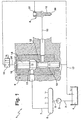
- a fuel injection device for internal combustion engines has a high-pressure fuel pump 2 , the suction side via a Kraftstofrise Arthur 3 with a fuel-filled low-pressure chamber 4 and the pressure side via the delivery line 5 with a high-pressure accumulator (common rail) 6 is connected. From this high-pressure accumulator 6, the high-pressure fuel is discharged via supply lines 7 to the individual, projecting into the combustion chamber of the engine to be supplied pressure-controlled injection valves 8 . To control the injection process each injector 8 is associated with an electrically actuated control valve 9 in the form of a 3/2-way valve.
- the control valve 9 has an axial through-bore 10 with an upper, middle and lower annular space 11, 12, 13 and as a control valve member on a run in the through hole 10 control piston 14 .
- the supply line 7 opens, and from the middle annulus 12 is a high pressure line 15 , which opens in a known manner in the injector 8 to a aufberichtbaren by a valve needle 16 of the injector 8 injection cross section of the injector 8.
- the control piston 14 connects the middle annular space 12 alternately with the upper annular space 11 or with the lower annular space 13, from which a low pressure chamber 4 leading discharge line 17 goes off.
- the adjustment movement of the control piston 14 is controlled by a solenoid valve 18 which is controlled by an electrical control unit (not shown), which processes a plurality of operating parameters of the engine to be supplied.
- Fig. 2 is an enlarged sectional view of the control valve 9, the middle annulus 12 is separated from the upper annulus 11 by a conical valve seat 19 and from the lower annulus 13 by an annular shoulder 20 .
- the cross section of the control piston 14 tapers from its upper end initially via two conically shaped upper annular end faces on a central piston portion 21 , opposite which a slide head 22 is widened at its lower end.
- the diameter of the middle piston portion 21 is smaller than the opening diameter of the valve seat 19 and the annular shoulder 20.
- the first upper annular end surface 23 is provided in the region of the upper annular space 11, and the second upper annular end surface forms a conical valve sealing surface 24 which is connected to the valve seat 19th interacts.
- This sealing seat formed between the valve sealing surface 24 and the valve seat 19 closes the upper annulus 11 with respect to the central annulus 12.
- the control piston 14 Adjacent to its conical valve sealing surface 24, the control piston 14 has a first valve control edge 25 formed by the lower edge of a collar 26 .
- the annular collar 26 is mating ground with little play in the valve seat 19 out, and its lower edge forms together with the valve seat 19 a slide valve.
- the distance of the first valve control edge 25 to the valve sealing surface 24, that is, the length of the annular collar is designated h1 .
- a second valve control edge 27 cooperates on the slide head 21, wherein the second sealing cross-section formed therebetween closes the connection between the middle and the lower annular space 12, 13.
- the closing stroke of the slide valve formed by the annular shoulder 20 and the second valve control edge 27 is denoted by h2 and at most as large as the length h1, ie h1 ⁇ h2.
- the fuel discharge from the lower annular space 13 in the discharge line 17 via an opening open to the lower end face 28 of the control piston 14 blind bore 29 discharges a trained as a throttle point transverse bore 30 and opens into the lower annular space 13.
- a hydraulic working chamber 31 is provided, which is delimited in the through-bore 10 by the upper end face 32 of the control piston 14 and to the solenoid valve 18 by an intermediate disk 33 .
- a discharge channel 34 discharging from the working space 31 is provided, which can be connected to the low-pressure space 4 via the magnetic valve 18 (FIG. 1).
- a filling bore 35 having a transverse opening 36 is provided in the control piston 14, the cross section of which is smaller than the cross section of the relief channel 34 and which therefore forms a throttle point.
- the transverse opening 36 extends below the first annular end face 23 of the control piston 14, so that the working space 31 is connected to the supply line 7 via the filling bore 35 at all times.
- the fuel injection device 1 shown in Figs. 1 and 2 operates in the following manner.
- a high-pressure fuel in the common high-pressure accumulator 6 is first set up via the high-pressure fuel pump 2, which continues through the various supply lines 7 to the respective control valves 9.
- the solenoid valve 18 is de-energized prior to the start of the injection phase, so that the discharge channel 34 is closed.
- the working space 31 is filled via the filling bore 35 with high fuel pressure and presses the control piston 14 due to the area ratio between the end face 32 and the first annular face 23 with the valve sealing surface 24 against the valve seat 19.
- the second sealing cross section between the second valve control edge 27 and the annular shoulder 20 is opened, so that the pressure in the high pressure passage 15 can relax to a certain residual pressure in the discharge line 17.
- the solenoid valve 18 is energized and thus the discharge channel 34 is released to the low-pressure chamber 4. Since the cross section of the discharge channel 34 is greater than that of the transverse opening 36 in the filling bore 35, the pressure in the working chamber 31 relaxes very quickly via the discharge channel 34 into the low-pressure space 4.
- the high-pressure fuel present at the annular end face 23 now suffices for the control piston 14 to move.
- valve sealing surface 24 first lifts off the valve seat 19, the first valve control edge 25 still sealing the connection to the middle annular space 12 despite this opened sealing seat.
- the slide valve is closed by abutment of the second valve control edge 27 on the annular shoulder 20.
- the first valve control edge 25 releases the sealing seat and the high pressure fuel in the supply line 7 flows at the central piston portion 21 along in the high pressure passage 15 to the injection valve 8 and lifts there in a known manner, the valve needle 16 against the restoring force of a valve spring 37 of the needle seat, so that the fuel is injected at the injection valve 8 via injection ports 38 into the combustion chamber of the engine to be supplied.
- the high-pressure injection at the injection valve 8 is through again Stromlosput the solenoid valve 18 is completed. Due to the now closed discharge channel 34 can over the filling hole 35 again a closing pressure in Build working space 31, so that the first valve control edge 25 again closes the valve seat 19 and thus the Connection of the supply line 7 to the high pressure passage 15 again is closed. Either at the same time, if h1 is equal to h2, or only after an additional stroke, though h1 is greater than h2, the gate valve is between the second valve control edge 27 and the annular shoulder 20 again controlled, so that in the high-pressure channel 15th high pressure fuel very quickly in the discharge line 17 relaxed, which is a quick needle closure has the fuel injection valve 8 result.
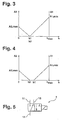
- FIG 5 shows the block diagram of the control valve 9 acting as a 3/2-way valve, in which the second annular space 12 is connected to the third annular space 13 either in the currentless state or to the first annular space 11 in the energized state.
- FIG. 6 40 denotes a second embodiment of a fuel injection device for internal combustion engines with pressure and cross-section controlled injection valves 41 .
- From the high pressure accumulator 6 goes to each injection valve 41 from an injection line 42 , which opens in a known manner in the injection valve 41 to a aufberichtbaren from a valve needle 43 of the injection valve 41 injection cross section of the injection valve 41.
- the injection is controlled by the control valve 9 in the injection pipe 42.
- the injection openings 44 of the injection valve 41 facing away from the end face 45 of the nozzle needle 43 defines a chamber 46 which is connectable via a discharge line 47 with the low-pressure chamber 4.
- This connection is hydraulically controlled by a 2/2-way control valve 48 whose high pressure line 49 designed control line via the control valve 9 'with a supply line 50 of the high-pressure accumulator 6 or with the discharge line 17 is connectable.
- high pressure control line ie at no-current control valve 9 '
- the 2/2-way control valve 48 is closed.
- valve needle 43 By energizing the control valve 9, the valve needle 43 is raised counter to the restoring force of a valve spring 51 from its needle seat so that the fuel is injected at the injection valve 8 via the injection ports 44 into the combustion chamber of the engine to be supplied via an increase in pressure. Due to the de-energized control valve 9 ', the 2/2-way control valve 48 is closed, and it therefore comes with the trapped in the chamber 46 fuel to a pressure increase, which serves to control the injection cross-section. Is reduced by energizing the control valve 9 ', the pressure in the high-pressure line 49 via the discharge line 17, opens the 2/2-way control valve 48, so that degrades the pressure prevailing in the chamber 46 via the discharge line 47. This causes a further stroke of the valve needle 43, whereby a larger injection cross-section 52 is released to the valve needle 43.
- the high pressure line 49 can either at least partially also on the high-pressure accumulator 6 to be integrated, which reduces the construction costs reduced, or a separately arranged Be control line.
Landscapes
- Engineering & Computer Science (AREA)
- Chemical & Material Sciences (AREA)
- Combustion & Propulsion (AREA)
- Mechanical Engineering (AREA)
- General Engineering & Computer Science (AREA)
- Physics & Mathematics (AREA)
- Fluid Mechanics (AREA)
- Fuel-Injection Apparatus (AREA)
Abstract
Description
- Fig. 1
- ein erstes Ausführungsbeispiel in einer schematischen Gesamtdarstellung, wobei ein für die Einspritzung verwendetes Steuerventil in vergrößerter Detailansicht dargestellt ist;
- Fig. 2
- eine vergrößerte Schnittansicht durch das Steuerventil der Fig. 1;
- Fign. 3 und 4
- Diagramme, die Öffnungsquerschnitte des Steuerventils der Fig. 2 in Abhängigkeit seiner Hubbewegung zeigen;
- Fig. 5
- das Blockschaltbild des Steuerventils der Fig. 2; und
- Fig. 6
- ein zweites Ausführungsbeispiel, bei dem das Steuerventil der Fig. 2 zur Querschnittssteuerung von Einspritzventilen verwendet wird.
Claims (7)
- Kraftstoffeinspritzvorrichtung (1; 40) für Brennkraftmaschinen, umfassend ein elektrisch angesteuertes Steuerventil (9; 9') mit einer axialen Durchgangsbohrung (10), die durch einen Ventilsitz (19) und einen Ringabsatz (20) in drei Ringräume (11, 12, 13) unterteilt ist, an die jeweils eine Zufuhrleitung (7; 50) für unter Hochdruck stehenden Kraftstoff, eine zu einem Einspritzventil (8; 41) abführende Hochdruckleitung (15; 49) und eine Entlastungsleitung (17) angeschlossen sind, und mit einem in der Durchgangsbohrung (10) geführten Steuerkolben (14), der eine mit dem Ventilsitz (19) zusammenwirkende Ventildichtfläche (24), einen Ringbund (26) mit einer ersten Ventilsteuerkante (25), die mit der die Sitzöffnung des Ventilsitzes (19) definierenden Bohrungswand der Durchgangsbohrung (10) zusammenwirkt, sowie eine zusammen mit dem Ringabsatz (20) ein Schieberventil bildende zweite Ventilsteuerkante (27) aufweist, wobei der Abstand (h1) der ersten Ventilsteuerkante (25) zur Ventildichtfläche (24) mindestens gleich dem Abstand (h2) zwischen zweiter Ventilsteuerkante (27) und Ringabsatz (20) bei geschlossenem Dichtsitz ist.
- Kraftstoffeinspritzvorrichtung nach Anspruch 1, dadurch gekennzeichnet, daß der Abstand (h1) der ersten Ventilsteuerkante (25) zur Ventildichtfläche (24) bei geschlossenem Dichtsitz größer als der Abstand (h2) zwischen zweiter Ventilsteuerkante (27) und Ringabsatz (20) ist.
- Kraftstoffeinspritzvorrichtung nach Anspruch 1 oder 2, dadurch gekennzeichnet, daß der Ringbund (26) an die Ventildichtfläche (24) angrenzt.
- Kraftstoffeinspritzvorrichtung nach einem der vorhergehenden Ansprüche, dadurch gekennzeichnet, daß sich die Ventildichtfläche (24) und/oder der Ventilsitz (19) in Schließrichtung des Steuerkolbens (14) konisch verjüngen.
- Kraftstoffeinspritzvorrichtung nach einem der vorhergehenden Ansprüche, dadurch gekennzeichnet, daß die Zufuhrleitung (7; 50) an einen Hochdruckspeicher (6) angeschlossen ist.
- Kraftstoffeinspritzvorrichtung nach einem der vorhergehenden Ansprüche, dadurch gekennzeichnet, daß ein von einer Ventilnadel (16; 43) des Einspritzventils (8; 41) aufsteuerbarer Einspritzquerschnitt des Einspritzventils (8; 41) über das Steuerventil (9) entweder mit der Zufuhrleitung (7) oder mit der Entlastungsleitung (17) verbindbar ist.
- Kraftstoffeinspritzvorrichtung nach einem der vorhergehenden Ansprüche, dadurch gekennzeichnet, daß das Steuerventil (9') zur Querschnittssteuerung des Einspritzventils (41) vorgesehen ist.
Applications Claiming Priority (3)
| Application Number | Priority Date | Filing Date | Title |
|---|---|---|---|
| DE10031278 | 2000-06-27 | ||
| DE2000131278 DE10031278A1 (de) | 2000-06-27 | 2000-06-27 | Kraftstoffeinspritzvorrichtung für Brennkraftmaschinen |
| PCT/DE2001/002355 WO2002001069A1 (de) | 2000-06-27 | 2001-06-26 | Kraftstoffeinspritzvorrichtung für brennkraftmaschinen |
Publications (2)
| Publication Number | Publication Date |
|---|---|
| EP1297253A1 EP1297253A1 (de) | 2003-04-02 |
| EP1297253B1 true EP1297253B1 (de) | 2005-12-21 |
Family
ID=7646974
Family Applications (1)
| Application Number | Title | Priority Date | Filing Date |
|---|---|---|---|
| EP20010953802 Expired - Lifetime EP1297253B1 (de) | 2000-06-27 | 2001-06-26 | Kraftstoffeinspritzvorrichtung für brennkraftmaschinen |
Country Status (5)
| Country | Link |
|---|---|
| US (1) | US6637409B2 (de) |
| EP (1) | EP1297253B1 (de) |
| JP (1) | JP2004502078A (de) |
| DE (2) | DE10031278A1 (de) |
| WO (1) | WO2002001069A1 (de) |
Families Citing this family (9)
| Publication number | Priority date | Publication date | Assignee | Title |
|---|---|---|---|---|
| DE10002702A1 (de) * | 2000-01-22 | 2001-08-02 | Bosch Gmbh Robert | Ventil zum Steuern von Flüssigkeiten |
| DE10141110A1 (de) * | 2001-08-22 | 2003-03-20 | Bosch Gmbh Robert | Kraftstoffeinspritzvorrichtung für Brennkraftmaschinen |
| EP1359316B1 (de) * | 2002-05-03 | 2007-04-18 | Delphi Technologies, Inc. | Kraftstoffeinspritzeinrichtung |
| JP2004301190A (ja) * | 2003-03-28 | 2004-10-28 | Aisin Seiki Co Ltd | 油圧制御装置 |
| FI117644B (fi) * | 2003-06-17 | 2006-12-29 | Waertsilae Finland Oy | Järjestely polttoaineen syöttölaitteistossa |
| DE10337574A1 (de) * | 2003-08-14 | 2005-03-10 | Bosch Gmbh Robert | Kraftstoffeinspritzeinrichtung für Brennkraftmaschinen |
| JP2005069135A (ja) * | 2003-08-26 | 2005-03-17 | Toyota Motor Corp | 燃料噴射装置 |
| EP1707801B1 (de) * | 2005-03-09 | 2008-06-04 | Delphi Technologies, Inc. | Ventilanordnung |
| DE112009004690A5 (de) * | 2009-04-24 | 2012-10-31 | Fev Gmbh | Kraftstoffeinspritzvorrichtung für eine verbrennungskraftmaschine, verbrennungskraftmaschine und verfahren zur kraftstoffeinspritzung in eine verbrennungskraftmaschine |
Family Cites Families (11)
| Publication number | Priority date | Publication date | Assignee | Title |
|---|---|---|---|---|
| US4275865A (en) * | 1977-08-24 | 1981-06-30 | Lucas Industries Limited | Fluid control valves |
| DE2759187A1 (de) * | 1977-12-31 | 1979-07-12 | Bosch Gmbh Robert | Kraftstoffeinspritzanlage mit mindestens einem kraftstoffeinspritzventil, insbesondere fuer grossmotoren |
| DE3629751C2 (de) * | 1986-09-01 | 1998-07-02 | Bosch Gmbh Robert | Voreinspritzvorrichtung für Brennkraftmaschinen |
| US4676273A (en) * | 1986-10-07 | 1987-06-30 | General Motors Corporation | Electro-hydraulic pressure regulating valve |
| AT408134B (de) * | 1995-06-06 | 2001-09-25 | Avl Verbrennungskraft Messtech | Speichereinspritzsystem für dieselbrennkraftmaschinen |
| DE19701879A1 (de) * | 1997-01-21 | 1998-07-23 | Bosch Gmbh Robert | Kraftstoffeinspritzeinrichtung für Brennkraftmaschinen |
| DE19709794A1 (de) * | 1997-03-10 | 1998-09-17 | Bosch Gmbh Robert | Ventil zum Steuern von Flüssigkeiten |
| DE19716221B4 (de) * | 1997-04-18 | 2007-06-21 | Robert Bosch Gmbh | Kraftstoffeinspritzeinrichtung mit Vor- und Haupteinspritzung bei Brennkraftmaschinen, insbesondere für schwer zündbare Kraftstoffe |
| DE19742073A1 (de) * | 1997-09-24 | 1999-03-25 | Bosch Gmbh Robert | Kraftstoffeinspritzvorrichtung für Brennkraftmaschinen |
| US5975139A (en) * | 1998-01-09 | 1999-11-02 | Caterpillar Inc. | Servo control valve for a hydraulically-actuated device |
| US5911245A (en) * | 1998-06-09 | 1999-06-15 | Caterpillar Inc. | Flow force spool valve |
-
2000
- 2000-06-27 DE DE2000131278 patent/DE10031278A1/de not_active Ceased
-
2001
- 2001-06-26 US US10/069,569 patent/US6637409B2/en not_active Expired - Fee Related
- 2001-06-26 EP EP20010953802 patent/EP1297253B1/de not_active Expired - Lifetime
- 2001-06-26 DE DE50108471T patent/DE50108471D1/de not_active Expired - Fee Related
- 2001-06-26 WO PCT/DE2001/002355 patent/WO2002001069A1/de not_active Ceased
- 2001-06-26 JP JP2002506365A patent/JP2004502078A/ja active Pending
Also Published As
| Publication number | Publication date |
|---|---|
| DE50108471D1 (de) | 2006-01-26 |
| US20020170535A1 (en) | 2002-11-21 |
| DE10031278A1 (de) | 2002-01-17 |
| US6637409B2 (en) | 2003-10-28 |
| WO2002001069A1 (de) | 2002-01-03 |
| EP1297253A1 (de) | 2003-04-02 |
| JP2004502078A (ja) | 2004-01-22 |
Similar Documents
| Publication | Publication Date | Title |
|---|---|---|
| EP0898650B1 (de) | Kraftstoffeinspritzeinrichtung für brennkraftmaschinen | |
| EP1991773B1 (de) | Brennstoffeinspritzventil für verbrennungskraftmaschinen | |
| DE19616812B4 (de) | Kraftstoffeinspritzvorrichtung | |
| EP0116168B1 (de) | Kraftstoffeinspritzpumpe | |
| EP1125046B1 (de) | Kraftstoffeinspritzsystem für eine Brennkraftmaschine mit einer Druckübersetzungseinheit | |
| EP0959243B1 (de) | Steuerventil für Kraftstoffeinspritzventil | |
| DE19519191A1 (de) | Einspritzventil | |
| DE4341546A1 (de) | Kraftstoffeinspritzeinrichtung für Brennkraftmaschinen | |
| DE10222196A1 (de) | Kraftstoffeinspritzventil für Brennkraftmaschinen | |
| EP0976924B1 (de) | Einspritzventil mit einem Servoventil | |
| DE4341545A1 (de) | Kraftstoffeinspritzeinrichtung für Brennkraftmaschinen | |
| DE19603435A1 (de) | Von Einspritzratenform- bzw. -gestaltungssteuerung geöffnetes Rückschlagventil für eine Brennstoffeinspritzdüse | |
| DE19823937B4 (de) | Servoventil für Kraftstoffeinspritzventil | |
| EP1297253B1 (de) | Kraftstoffeinspritzvorrichtung für brennkraftmaschinen | |
| DE10160588A1 (de) | Brennstoffeinspritzsystem mit gemeinsamer Betätigungsvorrichtung und Motor, der dieses verwendet | |
| DE19612721C2 (de) | Speichereinspritzsystem mit Voreinspritzung für eine Brennkraftmaschine | |
| EP1925812B1 (de) | Kraftstoffeinspritzventil für Brennkraftmaschinen | |
| EP1045975A1 (de) | Steuereinheit zur steuerung des druckaufbaus in einer pumpeneinheit | |
| DE10031574B4 (de) | Druckgesteuerter doppelschaltender Hochdruckinjektor | |
| DE69309085T2 (de) | Hochdruckkraftstoffeinspritzventil mit kraftstoffabflussventil | |
| EP1392965B1 (de) | Druckverstärker einer kraftstoffeinspritzeinrichtung | |
| DE19801169C1 (de) | Kraftstoffeinspritzsystem für Brennkraftmaschinen | |
| DE10141221A1 (de) | Druck-Hub-gesteuerter Injektor für Kraftstoffeinspritzsysteme | |
| EP1483499A1 (de) | Einrichtung zur druckmodulierten formung des einspritzverlaufes | |
| DE102006000461B4 (de) | Kraftstoffeinspritzventil |
Legal Events
| Date | Code | Title | Description |
|---|---|---|---|
| PUAI | Public reference made under article 153(3) epc to a published international application that has entered the european phase |
Free format text: ORIGINAL CODE: 0009012 |
|
| 17P | Request for examination filed |
Effective date: 20030127 |
|
| AK | Designated contracting states |
Kind code of ref document: A1 Designated state(s): AT BE CH CY DE DK ES FI FR GB GR IE IT LI LU MC NL PT SE TR Designated state(s): AT BE CH CY DE DK ES FI FR GB GR IE IT LI LU MC NL PT SE TR |
|
| RIN1 | Information on inventor provided before grant (corrected) |
Inventor name: GORDON, UWE Inventor name: KLENK, WOLFGANG Inventor name: MACK, MANFRED Inventor name: BRENK, ACHIM |
|
| RBV | Designated contracting states (corrected) |
Designated state(s): DE ES FR GB IT |
|
| 17Q | First examination report despatched |
Effective date: 20050401 |
|
| GRAP | Despatch of communication of intention to grant a patent |
Free format text: ORIGINAL CODE: EPIDOSNIGR1 |
|
| GRAS | Grant fee paid |
Free format text: ORIGINAL CODE: EPIDOSNIGR3 |
|
| GRAA | (expected) grant |
Free format text: ORIGINAL CODE: 0009210 |
|
| AK | Designated contracting states |
Kind code of ref document: B1 Designated state(s): DE ES FR GB IT |
|
| PG25 | Lapsed in a contracting state [announced via postgrant information from national office to epo] |
Ref country code: IT Free format text: LAPSE BECAUSE OF FAILURE TO SUBMIT A TRANSLATION OF THE DESCRIPTION OR TO PAY THE FEE WITHIN THE PRESCRIBED TIME-LIMIT;WARNING: LAPSES OF ITALIAN PATENTS WITH EFFECTIVE DATE BEFORE 2007 MAY HAVE OCCURRED AT ANY TIME BEFORE 2007. THE CORRECT EFFECTIVE DATE MAY BE DIFFERENT FROM THE ONE RECORDED. Effective date: 20051221 Ref country code: GB Free format text: LAPSE BECAUSE OF FAILURE TO SUBMIT A TRANSLATION OF THE DESCRIPTION OR TO PAY THE FEE WITHIN THE PRESCRIBED TIME-LIMIT Effective date: 20051221 |
|
| REG | Reference to a national code |
Ref country code: GB Ref legal event code: FG4D Free format text: NOT ENGLISH |
|
| REF | Corresponds to: |
Ref document number: 50108471 Country of ref document: DE Date of ref document: 20060126 Kind code of ref document: P |
|
| PG25 | Lapsed in a contracting state [announced via postgrant information from national office to epo] |
Ref country code: ES Free format text: LAPSE BECAUSE OF FAILURE TO SUBMIT A TRANSLATION OF THE DESCRIPTION OR TO PAY THE FEE WITHIN THE PRESCRIBED TIME-LIMIT Effective date: 20060401 |
|
| GBV | Gb: ep patent (uk) treated as always having been void in accordance with gb section 77(7)/1977 [no translation filed] |
Effective date: 20051221 |
|
| PGFP | Annual fee paid to national office [announced via postgrant information from national office to epo] |
Ref country code: DE Payment date: 20060818 Year of fee payment: 6 |
|
| PLBE | No opposition filed within time limit |
Free format text: ORIGINAL CODE: 0009261 |
|
| STAA | Information on the status of an ep patent application or granted ep patent |
Free format text: STATUS: NO OPPOSITION FILED WITHIN TIME LIMIT |
|
| 26N | No opposition filed |
Effective date: 20060922 |
|
| EN | Fr: translation not filed | ||
| PG25 | Lapsed in a contracting state [announced via postgrant information from national office to epo] |
Ref country code: FR Free format text: LAPSE BECAUSE OF FAILURE TO SUBMIT A TRANSLATION OF THE DESCRIPTION OR TO PAY THE FEE WITHIN THE PRESCRIBED TIME-LIMIT Effective date: 20070209 Ref country code: DE Free format text: LAPSE BECAUSE OF NON-PAYMENT OF DUE FEES Effective date: 20080101 |
|
| PG25 | Lapsed in a contracting state [announced via postgrant information from national office to epo] |
Ref country code: FR Free format text: LAPSE BECAUSE OF FAILURE TO SUBMIT A TRANSLATION OF THE DESCRIPTION OR TO PAY THE FEE WITHIN THE PRESCRIBED TIME-LIMIT Effective date: 20051221 |