EP1297720B1 - Transducteur electroacoustique a diaphragme remplacable chez l'utilisateur supportant deux enroulements entrelaces sans manipulation de fils - Google Patents
Transducteur electroacoustique a diaphragme remplacable chez l'utilisateur supportant deux enroulements entrelaces sans manipulation de fils Download PDFInfo
- Publication number
- EP1297720B1 EP1297720B1 EP01943710A EP01943710A EP1297720B1 EP 1297720 B1 EP1297720 B1 EP 1297720B1 EP 01943710 A EP01943710 A EP 01943710A EP 01943710 A EP01943710 A EP 01943710A EP 1297720 B1 EP1297720 B1 EP 1297720B1
- Authority
- EP
- European Patent Office
- Prior art keywords
- diaphragm
- coils
- conductors
- loudspeaker
- coil
- Prior art date
- Legal status (The legal status is an assumption and is not a legal conclusion. Google has not performed a legal analysis and makes no representation as to the accuracy of the status listed.)
- Expired - Lifetime
Links
Images



Classifications
-
- H—ELECTRICITY
- H04—ELECTRIC COMMUNICATION TECHNIQUE
- H04R—LOUDSPEAKERS, MICROPHONES, GRAMOPHONE PICK-UPS OR LIKE ACOUSTIC ELECTROMECHANICAL TRANSDUCERS; ELECTRIC HEARING AIDS; PUBLIC ADDRESS SYSTEMS
- H04R9/00—Transducers of moving-coil, moving-strip, or moving-wire type
- H04R9/02—Details
- H04R9/04—Construction, mounting, or centering of coil
-
- H—ELECTRICITY
- H04—ELECTRIC COMMUNICATION TECHNIQUE
- H04R—LOUDSPEAKERS, MICROPHONES, GRAMOPHONE PICK-UPS OR LIKE ACOUSTIC ELECTROMECHANICAL TRANSDUCERS; ELECTRIC HEARING AIDS; PUBLIC ADDRESS SYSTEMS
- H04R7/00—Diaphragms for electromechanical transducers; Cones
-
- H—ELECTRICITY
- H04—ELECTRIC COMMUNICATION TECHNIQUE
- H04R—LOUDSPEAKERS, MICROPHONES, GRAMOPHONE PICK-UPS OR LIKE ACOUSTIC ELECTROMECHANICAL TRANSDUCERS; ELECTRIC HEARING AIDS; PUBLIC ADDRESS SYSTEMS
- H04R7/00—Diaphragms for electromechanical transducers; Cones
- H04R7/16—Mounting or tensioning of diaphragms or cones
- H04R7/18—Mounting or tensioning of diaphragms or cones at the periphery
Definitions
- This invention relates to electroacoustic transducers which act as Loudspeakers and in particular to thin diaphragm type of Audio transducers, which are converting electrical ( audio ) energy, into movement of a sound emitting diaphragm.
- Such transducers which are called Planar Loudspeakers or some times as Ribbon Loudspeakers, in the past years were not enjoying the same popularity as the cone-type speakers -inspite of the superior performance of the said diaphragmatic types- due primarily their high cost, and the different performance characteristics.
- the conventional, cone or dome Loudspeakers are known as electromagnetic motor actuated point sound source emitting devices.
- cones or domes As it is known to those skilled, in the art of sound reproduction, the" pistonic " operation of cones or domes is not at all secured throughout their operating range, and as a result not a uniform sound emitting activity can exist from the surface of cone or dome. Sound waves emitted from the peripheral portion of cone or dome may be out of phase to the emitted sound, from their central part areas, at any given instant. This is an inherent distorting characteristic of cone-dome Loudspeakers, created by the mode of activation and the shape of the activated sound emitting surfaces. An additional distortion producing factor, is the moving mass of cone or dome which has to be moved in accordance with the waveform of the audio current.
- the demands of the audio signal can be so great in terms of moving speed and acceleration, that (the inertia mass ) weight (mass) of the vibrating parts is a great limiting factor.
- the reproduced waveform is greatly affected especially in high frequencies where the relative inertias cannot be met by the electromagnetic motor moving the heavy cones or domes.
- planar speakers Numerous type of such planar speakers can be found, being used in Hi Fi systems, giving very satisfactory acoustic results.
- Most of the planar transducers existing in commercial production today make use of Polyester or Polyimid diaphragm which has on its surface laminated a very thin layer of parallel aluminum current carrying conductors. The said diaphragm is evenly stretched over rows of magnets, the magnetic lines of which, intersect the diaphragm with current currying conductors at 90°. The interaction of the magnetic lines and the magnetic field created by the current flowing the conductors, results in a force, moving either forward or backward the diaphragm in accordance with the direction - at any instant- of the flowing audio current.
- the diaphragm with the current carrying conductors is the motor and the sound emitting member of the Planar loudspeaker.
- planar loudspeakers are characterized by distinct advantages in performance over the cone-dome loudspeakers.
- Planar loudspeakers exhibit, wider bandwidth, Linear phase response, constant impedance, greatly improved transient response and lower distortion.
- planar loudspeakers The high cost of the planar loudspeakers is somehow anticipated, considering their distinct acoustic merits.
- the disappointment of the user comes, when the delicate vibrating diaphragm happens to fail, either by mechanical failure or by thermal failure of the coil. In such situation, all the rest expensive structure of the planar loudspeaker is wasted as laying inoperative.
- Primary object of the present invention is to provide a planar sound reproducer with excellent performance characteristics, the values of which are secured, and maintained at all times by offering:
- the replacement of the diaphragm is accomplished by the user in a very simple operation, without the need of manipulating wires or soldering- de-soldering means, as this is necessary in prior art equipment.
- the diaphragm of commercial planar speakers employ for driving, single coil, in contrast, with the present invention which provides two ( binary) interlaced coil , for simultaneous driving.
- the diaphragm in addition to the easy field replacement, is characterized by two symmetrical coils configuration, which are interlaced, in a manner of being the one into each other, thus occupying the same area of the said diaphragm and securing the fact that the two coils are absolutely identical with all electrical characteristics such as Resistance, Impedance, Inductance being absolutely equal.
- Such Binary Interlaced Coils can be laid, in a multiplicity of similar B.I.C. executions, on the same long diaphragm tensioning adjustment means, for obtaining desired low frequency operation.
- a long and slim loudspeaker embodying in its diaphragm a multiplicity of binary interlace coils, can lead to the design of full range hybrid speaker driver, with line source behavior.
- the two coils in the present invention are characterized by symmetricity and equality of their parameters, a condition which permit the creation of several combinations of impedance networks, which can act as the output loads of an amplifier:
- An other object of the present invention is the character of the exchangeable diaphragm assembly and the way the totality of the coils conductors are energized by the magnetic field.
- the semicircular sections of the interlaced coils which are at the two ends of the longitudinal axis of the diaphragm are not clamped, but free to move, and in addition the semicircular section of the conductors are intersected by the magnetic flux lines exactly as the linear section of the conductors.
- Fig ( 5 ) shows these directions along the three geometric axes, as the Law is examined in three points along a typical turn of our diaphragm, where is confirmed that the Force ( F ) has the same direction in the linear and the semicircular section of the conductor, thus the semicircular section is actively contributing in the sound emitting activity
- the various diaphragmatic loudspeakers of prior art invariably have the extreme sections of their elongated coils, not actively participating in the force producing process, and in some cases they are clamped and immovable.
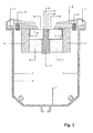
- FIG. 1 shows all the main components ; which compose the present invention and which are : the upper plate pole 1 , the diaphragm assembly 2, the central pole 3, the side poles 4, the Neodymium magnets 5, which are required for the construction of diaphragmatic electroacoustic transducer in accordance with the present invention.
- the members 1, 3, 4 are made of low carbon soft iron material
- FIG 2 shows the components 1 , 2, 3, 4, 5, assembled and the created two air gaps 22 , between upper plate pole 1 , and the central pole 3 .
- FIG. 2 shows the complete transducer assembly installed in its aluminium enclosure 6, as indicated in Line A - A' cut of FIG. 1, FIG. 2A shows in perspective view, the complete loudspeaker assembled and the two covers 8 being in place, thus realizing the contact of each coil of the diaphragm, with the respective terminals 16 outside of each plastic cover 8 .
- the upper plate 1 is machined in highly polished surfaces for low magnetic losses when attached by six screws 1B to side poles 4. Following this attachment of 1 to 4 , the Neodymium magnets 5 together with the central pole 3, are put in place, with appropriate adhesive agent. This assembly procedure always takes care that the upper plate 1 is the South pole of the magnets and the central pole 3 is the North pole. By convention we consider that the direction of magnetic flux lines have a direction from N- to - S as indicated in the analysis of FIG. 5 .
- the groove 23 of the upper part of the central pole 3 it should be given the two reasons of the groove 23.
- the flux lines traversing the air gap 22 are mostly departing from the two banks 21 , of the groove 23 and , very few lines departing from the bed 23 of the groove.
- the groove geometry is examined in conjunction with geometry of the two interlaced coils will be apparent that the central section of the diaphragm 2A, is not covered by coil conductors and therefore any lines intersecting that section are a waste.
- any lines reduced from departing the inner part of the groove 23 of the central pole 3 are added to the useful part of flux lines departing from the groove banks 21 .
- An additional usefulness of the groove is the filling of the bed by a soft wool thread, which is " overflowing " the bed, and thus at extreme excursions of the diaphragm, the wool thread acts as acoustic bumper.
- the magnetic system is ready to accept the exchangeable diaphragm assembly 2 .
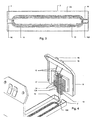
- the diaphragm assembly 2 is inserted in its operating position by holding the frame from the side 2D and sliding the long sides 2C between the poles 4 and the short side 2B with the opening, better showing in FIG 4 , allowing the passage, without the thin part 3A of the central pole 3 being an obstacle.
- the magnetic assembly which comprises an upper plate pole 1 , a center pole 3 the side poles 4, the Neodymium magnets 5, can now be inserted in the aluminium enclosure 6 and fixed in place by four hexagon headless screws 1A threaded on the upper pole 1 .
- the upper pole 1 squeezes a ferrous metal sheet 7 which acts as magnetic shielding and at the same time it immobilizes the magnetic assembly inside the aluminium enclosure, by anchoring it in four different points 1A x 4, as per FIG. 1 , FIG. 2A .
- the diaphragm assembly 2 shown in FIG 3 and FIG 4 is in its operating place FIG. 4 , ready to accept the spring loaded contacts 13 , 13C which are better shown on FIG 1 and realize their electrical access from the outside contacts 16 .
- FIG 3 are shown the two pairs of contact islands 9, 9A and 10, 10A corresponding to the two interlaced coils 11 and 12 respectively.
- each cover is identical plastic pieces and are airtightly closing the inside of the loudspeaker. This is accomplished by providing a soft gasket material which is placed at the bottom of guiding groove 17 .
- the guiding groove 17 is playing another role, which is riding on the edge of the aluminium enclosure during the closing operation, guides the cover to its final closing position, at which should be precisely making the electrical contact operation.
- the inside of each cover is characterized by the two spring 14 , the spring loaded contact carrier 13 which is cross shaped and which is a copper clad material, as that used in printed circuit boards, of 2 mm thickness.
- the contact carrier 13 is separated in two contacting copper areas 13A along its longitudinal dimension, on the one side having soldered the pair of gold plated contacts 13B , 13C, FIG. 1 and on the other side are attached by soldering, one pair of flexible conductors 15, the free ends of which are soldered on the inside riveting member of the terminals 16 , supported on the outside of the cover plastic cover 8 .
- FIG. 4 shows by dashed lines the path or routing of the spring loaded contacts and the eventual contact with contact islands 10, 10A , which takes place at the end of the transducer covering operation.
- the spring compression of both covers applied on each extremity of the diaphragm assembly 2 , through the contact islands 9 , 9A and 10, 10A besides the electrical contact making action, they hold firmly the diaphragm assembly 2 to its proper operating position. This position bring the two coils at 0.6mm below the lower surface of upper plate 1 and 0.6mm above the two banks 21 of the central pole 3.
- FIG 5 shows the three vectors F, B, i along the three geometric axes, applied in points along the linear sections of the coil 24 as well as the semicircular sections of the coil 24 , where the perpendicularity of B and the direction of i is applied on the tangent on the application point.
Landscapes
- Engineering & Computer Science (AREA)
- Physics & Mathematics (AREA)
- Acoustics & Sound (AREA)
- Signal Processing (AREA)
- Multimedia (AREA)
- Audible-Bandwidth Dynamoelectric Transducers Other Than Pickups (AREA)
- Diaphragms For Electromechanical Transducers (AREA)
- Piezo-Electric Transducers For Audible Bands (AREA)
Claims (11)
Applications Claiming Priority (3)
| Application Number | Priority Date | Filing Date | Title |
|---|---|---|---|
| GR2000100217 | 2000-07-03 | ||
| GR20000100217A GR1004325B (el) | 2000-07-03 | 2000-07-03 | Ηλεκτροακουστικος μορφοτροπεας με διαφραγμα που φερει δυο ενδοπλεκομενα πηνια |
| PCT/GR2001/000029 WO2002003748A2 (fr) | 2000-07-03 | 2001-06-28 | Transducteur electroacoustique a diaphragme remplaçable chez l'utilisateur supportant deux enroulements entrelaces sans manipulation de fils |
Publications (2)
| Publication Number | Publication Date |
|---|---|
| EP1297720A2 EP1297720A2 (fr) | 2003-04-02 |
| EP1297720B1 true EP1297720B1 (fr) | 2004-02-25 |
Family
ID=10944311
Family Applications (1)
| Application Number | Title | Priority Date | Filing Date |
|---|---|---|---|
| EP01943710A Expired - Lifetime EP1297720B1 (fr) | 2000-07-03 | 2001-06-28 | Transducteur electroacoustique a diaphragme remplacable chez l'utilisateur supportant deux enroulements entrelaces sans manipulation de fils |
Country Status (7)
| Country | Link |
|---|---|
| US (1) | US6956953B2 (fr) |
| EP (1) | EP1297720B1 (fr) |
| AT (1) | ATE260535T1 (fr) |
| AU (1) | AU2001266241A1 (fr) |
| DE (1) | DE60102158T2 (fr) |
| GR (1) | GR1004325B (fr) |
| WO (1) | WO2002003748A2 (fr) |
Families Citing this family (17)
| Publication number | Priority date | Publication date | Assignee | Title |
|---|---|---|---|---|
| KR20040035762A (ko) * | 2001-09-11 | 2004-04-29 | 소니온키르크 에이/에스 | 2개의 진동판을 구비한 전기 음향 변환기 |
| KR20040081470A (ko) * | 2002-01-25 | 2004-09-21 | 소니온 호르젠스 에이/에스 | 집적된 코일을 구비한 플랙서블 다이어프램 |
| TW200401580A (en) * | 2002-04-25 | 2004-01-16 | Koninkl Philips Electronics Nv | Loudspeaker with a first and a second diaphragm body |
| US6778677B2 (en) | 2002-07-16 | 2004-08-17 | C. Ronald Coffin | Repairable electromagnetic linear motor for loudspeakers and the like |
| WO2004049751A1 (fr) * | 2002-11-28 | 2004-06-10 | Matsushita Electric Industrial Co., Ltd. | Haut-parleur |
| CN2593507Y (zh) * | 2003-01-13 | 2003-12-17 | 深圳市美欧电子股份有限公司 | 微型动圈式发声器件磁路与音圈装置 |
| JP3896970B2 (ja) * | 2003-01-31 | 2007-03-22 | 松下電器産業株式会社 | スピーカ |
| US7450729B2 (en) | 2003-04-09 | 2008-11-11 | Harman International Industries, Incorporated | Low-profile transducer |
| US7333620B2 (en) | 2003-04-09 | 2008-02-19 | Harman International Industries, Incorporated | Acoustic transducer with mechanical balancing |
| US7412065B2 (en) | 2003-04-09 | 2008-08-12 | Harman International Industries, Incorporated | Acoustic transducer with folded diaphragm |
| JP5094404B2 (ja) * | 2004-10-21 | 2012-12-12 | シュアー インコーポレイテッド | リボン型音響変換器構造 |
| JP5100546B2 (ja) * | 2007-07-30 | 2012-12-19 | パナソニック株式会社 | 電気音響変換器 |
| US8283258B2 (en) * | 2007-08-16 | 2012-10-09 | Micron Technology, Inc. | Selective wet etching of hafnium aluminum oxide films |
| US8345897B2 (en) * | 2008-03-31 | 2013-01-01 | Mitsubishi Electric Engineering Co., Ltd | Electromagnetic conversion unit |
| US9197965B2 (en) | 2013-03-15 | 2015-11-24 | James J. Croft, III | Planar-magnetic transducer with improved electro-magnetic circuit |
| JP2015080064A (ja) * | 2013-10-16 | 2015-04-23 | モレックス インコーポレイテドMolex Incorporated | 電気音響変換器 |
| CN116320910B (zh) * | 2023-03-14 | 2025-01-28 | 中国科学院声学研究所 | 一种基于动圈式驱动机理实现的水下甚低频声源 |
Family Cites Families (7)
| Publication number | Priority date | Publication date | Assignee | Title |
|---|---|---|---|---|
| JPS60204199A (ja) * | 1984-03-28 | 1985-10-15 | Toshiba Corp | スピ−カ装置 |
| US4856071A (en) | 1987-08-28 | 1989-08-08 | Electromagnetic Research And Development | Planar loudspeaker system |
| US5003609A (en) | 1988-02-15 | 1991-03-26 | Foster Electric Co., Ltd. | Whole-surface driven speaker |
| GB2221796B (en) * | 1988-08-09 | 1992-01-08 | Gearing & Watson | Electromagnetic devices |
| US5009607A (en) * | 1989-07-24 | 1991-04-23 | Rogers Corporation | Flexible circuit connector |
| JPH08154296A (ja) * | 1994-11-28 | 1996-06-11 | Matsushita Electric Ind Co Ltd | スリム矩形スピーカ |
| JP3812150B2 (ja) * | 1998-06-18 | 2006-08-23 | 松下電器産業株式会社 | スピーカ |
-
2000
- 2000-07-03 GR GR20000100217A patent/GR1004325B/el unknown
-
2001
- 2001-06-28 US US10/049,659 patent/US6956953B2/en not_active Expired - Fee Related
- 2001-06-28 EP EP01943710A patent/EP1297720B1/fr not_active Expired - Lifetime
- 2001-06-28 DE DE60102158T patent/DE60102158T2/de not_active Expired - Fee Related
- 2001-06-28 AT AT01943710T patent/ATE260535T1/de not_active IP Right Cessation
- 2001-06-28 WO PCT/GR2001/000029 patent/WO2002003748A2/fr not_active Ceased
- 2001-06-28 AU AU2001266241A patent/AU2001266241A1/en not_active Abandoned
Also Published As
| Publication number | Publication date |
|---|---|
| WO2002003748A2 (fr) | 2002-01-10 |
| US6956953B2 (en) | 2005-10-18 |
| ATE260535T1 (de) | 2004-03-15 |
| GR1004325B (el) | 2003-09-05 |
| WO2002003748A3 (fr) | 2002-12-05 |
| GR20000100217A (el) | 2002-03-29 |
| EP1297720A2 (fr) | 2003-04-02 |
| US20030002696A1 (en) | 2003-01-02 |
| DE60102158D1 (de) | 2004-04-01 |
| AU2001266241A1 (en) | 2002-01-14 |
| DE60102158T2 (de) | 2004-12-30 |
Similar Documents
| Publication | Publication Date | Title |
|---|---|---|
| US6956953B2 (en) | Electroacoustic transducer with field replaceable diaphragm carrying two interlaced coils, without manipulating any wires | |
| US3141071A (en) | Full range electroacoustic transducers | |
| US3829623A (en) | Planar voice coil loudspeaker | |
| US4037061A (en) | Planar pattern voice coil audio transducer | |
| US4273968A (en) | Electroacoustic transducer with magnetic flux directed slantly across a diaphragm | |
| JP3192372B2 (ja) | 薄型電磁変換器 | |
| EP1434463A2 (fr) | Transducteur électroacoustique et dispositif électronique avec un tel transducteur | |
| US4531025A (en) | Loudspeaker with commutated coil drive | |
| EP1304903A2 (fr) | Transducteur électroacoustique et dispositif électronique | |
| JP2500609Y2 (ja) | ダイナミックトランスジュ―サ | |
| US7020301B2 (en) | Loudspeaker | |
| EP1182907B1 (fr) | Transducteur électro-acoustique | |
| KR20040081470A (ko) | 집적된 코일을 구비한 플랙서블 다이어프램 | |
| JP3997133B2 (ja) | 電気音響変換器及び電子機器 | |
| US4276452A (en) | Membrane type electro-acoustic transducer | |
| US4612420A (en) | Loudspeaker system for converting a digitized electric signal into an acoustic signal | |
| KR20230098143A (ko) | 단일 영구 자석 및 하나 이상의 음성 코일에 의해 구동되는 플랫 스피커 | |
| US20060023912A1 (en) | Electroacoustic transducer with field replaceable diaphragm carrying two interlaced coils, without manipulating any wires | |
| EP0077228A2 (fr) | Transducteur électroacoustique | |
| JPH11187484A (ja) | スピーカ | |
| CN115955636A (zh) | 一种平面扬声器及耳机 | |
| EP1881732A1 (fr) | Suspension magnétique d'une membrane | |
| JP2996842B2 (ja) | スピーカ | |
| CN115996347B (zh) | 平面扬声器及耳机 | |
| JP2001333492A (ja) | リボンスピーカ |
Legal Events
| Date | Code | Title | Description |
|---|---|---|---|
| PUAI | Public reference made under article 153(3) epc to a published international application that has entered the european phase |
Free format text: ORIGINAL CODE: 0009012 |
|
| 17P | Request for examination filed |
Effective date: 20020524 |
|
| AK | Designated contracting states |
Kind code of ref document: A2 Designated state(s): AT BE CH CY DE DK ES FI FR GB GR IE IT LI LU MC NL PT SE TR |
|
| AX | Request for extension of the european patent |
Extension state: AL LT LV MK RO SI |
|
| 17Q | First examination report despatched |
Effective date: 20030319 |
|
| GRAH | Despatch of communication of intention to grant a patent |
Free format text: ORIGINAL CODE: EPIDOS IGRA |
|
| RIC1 | Information provided on ipc code assigned before grant |
Ipc: 7H 04R 7/18 A Ipc: 7H 04R 9/04 B |
|
| RIC1 | Information provided on ipc code assigned before grant |
Ipc: 7H 04R 7/18 A Ipc: 7H 04R 9/04 B |
|
| RIC1 | Information provided on ipc code assigned before grant |
Ipc: 7H 04R 9/04 B Ipc: 7H 04R 7/18 A |
|
| GRAS | Grant fee paid |
Free format text: ORIGINAL CODE: EPIDOSNIGR3 |
|
| GRAA | (expected) grant |
Free format text: ORIGINAL CODE: 0009210 |
|
| AK | Designated contracting states |
Kind code of ref document: B1 Designated state(s): AT BE CH CY DE DK ES FI FR GB GR IE IT LI LU MC NL PT SE TR |
|
| PG25 | Lapsed in a contracting state [announced via postgrant information from national office to epo] |
Ref country code: IT Free format text: LAPSE BECAUSE OF FAILURE TO SUBMIT A TRANSLATION OF THE DESCRIPTION OR TO PAY THE FEE WITHIN THE PRESCRIBED TIME-LIMIT;WARNING: LAPSES OF ITALIAN PATENTS WITH EFFECTIVE DATE BEFORE 2007 MAY HAVE OCCURRED AT ANY TIME BEFORE 2007. THE CORRECT EFFECTIVE DATE MAY BE DIFFERENT FROM THE ONE RECORDED. Effective date: 20040225 Ref country code: TR Free format text: LAPSE BECAUSE OF FAILURE TO SUBMIT A TRANSLATION OF THE DESCRIPTION OR TO PAY THE FEE WITHIN THE PRESCRIBED TIME-LIMIT Effective date: 20040225 Ref country code: FI Free format text: LAPSE BECAUSE OF FAILURE TO SUBMIT A TRANSLATION OF THE DESCRIPTION OR TO PAY THE FEE WITHIN THE PRESCRIBED TIME-LIMIT Effective date: 20040225 Ref country code: BE Free format text: LAPSE BECAUSE OF FAILURE TO SUBMIT A TRANSLATION OF THE DESCRIPTION OR TO PAY THE FEE WITHIN THE PRESCRIBED TIME-LIMIT Effective date: 20040225 Ref country code: CH Free format text: LAPSE BECAUSE OF FAILURE TO SUBMIT A TRANSLATION OF THE DESCRIPTION OR TO PAY THE FEE WITHIN THE PRESCRIBED TIME-LIMIT Effective date: 20040225 Ref country code: FR Free format text: LAPSE BECAUSE OF FAILURE TO SUBMIT A TRANSLATION OF THE DESCRIPTION OR TO PAY THE FEE WITHIN THE PRESCRIBED TIME-LIMIT Effective date: 20040225 Ref country code: CY Free format text: LAPSE BECAUSE OF FAILURE TO SUBMIT A TRANSLATION OF THE DESCRIPTION OR TO PAY THE FEE WITHIN THE PRESCRIBED TIME-LIMIT Effective date: 20040225 Ref country code: NL Free format text: LAPSE BECAUSE OF FAILURE TO SUBMIT A TRANSLATION OF THE DESCRIPTION OR TO PAY THE FEE WITHIN THE PRESCRIBED TIME-LIMIT Effective date: 20040225 Ref country code: AT Free format text: LAPSE BECAUSE OF FAILURE TO SUBMIT A TRANSLATION OF THE DESCRIPTION OR TO PAY THE FEE WITHIN THE PRESCRIBED TIME-LIMIT Effective date: 20040225 Ref country code: LI Free format text: LAPSE BECAUSE OF FAILURE TO SUBMIT A TRANSLATION OF THE DESCRIPTION OR TO PAY THE FEE WITHIN THE PRESCRIBED TIME-LIMIT Effective date: 20040225 |
|
| REG | Reference to a national code |
Ref country code: GB Ref legal event code: FG4D |
|
| REG | Reference to a national code |
Ref country code: CH Ref legal event code: EP |
|
| REG | Reference to a national code |
Ref country code: IE Ref legal event code: FG4D |
|
| REF | Corresponds to: |
Ref document number: 60102158 Country of ref document: DE Date of ref document: 20040401 Kind code of ref document: P |
|
| PG25 | Lapsed in a contracting state [announced via postgrant information from national office to epo] |
Ref country code: DK Free format text: LAPSE BECAUSE OF FAILURE TO SUBMIT A TRANSLATION OF THE DESCRIPTION OR TO PAY THE FEE WITHIN THE PRESCRIBED TIME-LIMIT Effective date: 20040525 Ref country code: GR Free format text: LAPSE BECAUSE OF FAILURE TO SUBMIT A TRANSLATION OF THE DESCRIPTION OR TO PAY THE FEE WITHIN THE PRESCRIBED TIME-LIMIT Effective date: 20040525 Ref country code: SE Free format text: LAPSE BECAUSE OF FAILURE TO SUBMIT A TRANSLATION OF THE DESCRIPTION OR TO PAY THE FEE WITHIN THE PRESCRIBED TIME-LIMIT Effective date: 20040525 |
|
| PG25 | Lapsed in a contracting state [announced via postgrant information from national office to epo] |
Ref country code: ES Free format text: LAPSE BECAUSE OF FAILURE TO SUBMIT A TRANSLATION OF THE DESCRIPTION OR TO PAY THE FEE WITHIN THE PRESCRIBED TIME-LIMIT Effective date: 20040605 |
|
| PG25 | Lapsed in a contracting state [announced via postgrant information from national office to epo] |
Ref country code: IE Free format text: LAPSE BECAUSE OF NON-PAYMENT OF DUE FEES Effective date: 20040628 Ref country code: LU Free format text: LAPSE BECAUSE OF NON-PAYMENT OF DUE FEES Effective date: 20040628 |
|
| PG25 | Lapsed in a contracting state [announced via postgrant information from national office to epo] |
Ref country code: MC Free format text: LAPSE BECAUSE OF NON-PAYMENT OF DUE FEES Effective date: 20040630 |
|
| NLV1 | Nl: lapsed or annulled due to failure to fulfill the requirements of art. 29p and 29m of the patents act | ||
| LTIE | Lt: invalidation of european patent or patent extension |
Effective date: 20040225 |
|
| REG | Reference to a national code |
Ref country code: CH Ref legal event code: PL |
|
| NLXE | Nl: other communications concerning ep-patents (part 3 heading xe) |
Free format text: A REQUEST FOR RESTORATION TO THE PRIOR STATE (ARTICLE 23 OF THE PATENTS ACT 1995) HAS BEEN FILED ON 20040806. |
|
| NLXE | Nl: other communications concerning ep-patents (part 3 heading xe) |
Free format text: HET INGEDIENTE VERZOEK TOT HERSTEL IN DE VORIGE TOESTAND, ALS BEDOELD IN ARTIKEL 23 VAN DE RIJKSOCTROOIWET 1995 (ZIE PUBLICATIE IN RUBRIEK XE VAN DE INDUSTRIELE EIGENDOM VAN 20041001/10) IS INGEWILLIGD; HET HERSTEL IS AANGETEKEND IN HET OCTROOIREGISTER. |
|
| PLBE | No opposition filed within time limit |
Free format text: ORIGINAL CODE: 0009261 |
|
| STAA | Information on the status of an ep patent application or granted ep patent |
Free format text: STATUS: NO OPPOSITION FILED WITHIN TIME LIMIT |
|
| EN | Fr: translation not filed | ||
| 26N | No opposition filed |
Effective date: 20041126 |
|
| REG | Reference to a national code |
Ref country code: IE Ref legal event code: MM4A |
|
| GBPC | Gb: european patent ceased through non-payment of renewal fee |
Effective date: 20050628 |
|
| REG | Reference to a national code |
Ref country code: GB Ref legal event code: 728V |
|
| REG | Reference to a national code |
Ref country code: GB Ref legal event code: 728Y |
|
| PG25 | Lapsed in a contracting state [announced via postgrant information from national office to epo] |
Ref country code: PT Free format text: LAPSE BECAUSE OF NON-PAYMENT OF DUE FEES Effective date: 20040725 |
|
| PGFP | Annual fee paid to national office [announced via postgrant information from national office to epo] |
Ref country code: DE Payment date: 20080730 Year of fee payment: 8 |
|
| PG25 | Lapsed in a contracting state [announced via postgrant information from national office to epo] |
Ref country code: DE Free format text: LAPSE BECAUSE OF NON-PAYMENT OF DUE FEES Effective date: 20100101 |
|
| PGFP | Annual fee paid to national office [announced via postgrant information from national office to epo] |
Ref country code: NL Payment date: 20110628 Year of fee payment: 11 |
|
| PGFP | Annual fee paid to national office [announced via postgrant information from national office to epo] |
Ref country code: GB Payment date: 20110725 Year of fee payment: 11 |
|
| REG | Reference to a national code |
Ref country code: NL Ref legal event code: V1 Effective date: 20130101 |
|
| GBPC | Gb: european patent ceased through non-payment of renewal fee |
Effective date: 20120628 |
|
| PG25 | Lapsed in a contracting state [announced via postgrant information from national office to epo] |
Ref country code: NL Free format text: LAPSE BECAUSE OF FAILURE TO SUBMIT A TRANSLATION OF THE DESCRIPTION OR TO PAY THE FEE WITHIN THE PRESCRIBED TIME-LIMIT Effective date: 20130101 Ref country code: GB Free format text: LAPSE BECAUSE OF NON-PAYMENT OF DUE FEES Effective date: 20120628 |