EP1297759B1 - Verschlusseinrichtung - Google Patents
Verschlusseinrichtung Download PDFInfo
- Publication number
- EP1297759B1 EP1297759B1 EP02021717A EP02021717A EP1297759B1 EP 1297759 B1 EP1297759 B1 EP 1297759B1 EP 02021717 A EP02021717 A EP 02021717A EP 02021717 A EP02021717 A EP 02021717A EP 1297759 B1 EP1297759 B1 EP 1297759B1
- Authority
- EP
- European Patent Office
- Prior art keywords
- shell
- closing
- fastened
- elastic means
- arms
- Prior art date
- Legal status (The legal status is an assumption and is not a legal conclusion. Google has not performed a legal analysis and makes no representation as to the accuracy of the status listed.)
- Expired - Lifetime
Links
- 230000033001 locomotion Effects 0.000 description 4
- 230000000295 complement effect Effects 0.000 description 2
- 238000004873 anchoring Methods 0.000 description 1
- 238000006243 chemical reaction Methods 0.000 description 1
- 230000008878 coupling Effects 0.000 description 1
- 238000010168 coupling process Methods 0.000 description 1
- 238000005859 coupling reaction Methods 0.000 description 1
- 238000004519 manufacturing process Methods 0.000 description 1
- 230000007246 mechanism Effects 0.000 description 1
- 230000010355 oscillation Effects 0.000 description 1
- 230000006641 stabilisation Effects 0.000 description 1
- 238000011105 stabilization Methods 0.000 description 1
Images


Classifications
-
- A—HUMAN NECESSITIES
- A41—WEARING APPAREL
- A41F—GARMENT FASTENINGS; SUSPENDERS
- A41F1/00—Fastening devices specially adapted for garments
Definitions
- the present invention relates to the technical field concerning devices for closing articles, e.g. clothes, leatherwear in general, rucksacks and the like.
- Different closing elements are used in clothes production field, such as buttons, loop fastenings, snap-hooks and the like, while for the leatherwear and especially for bags closing zip closings, magnetic elements, and butterfly-shaped closings are used.
- the button closing includes fastening a button to a first article, e.g. a first vertical end of a clothing piece, and making a button hole in a second article, e.g. in the second vertical end of the clothing piece.
- the button hole allows the button to pass therethrough in order to close the clothing piece and stabilize the mutual position of the first and second end and maintain their closing.
- a loop fastening, or "frog” is a clothing piece closure including two parts, i.e. a piece of thread forming a slipknot, sewn to one side of the clothing piece, and an engaging element, e.g. a button fastened, by means of a piece of identical thread, to the other side of the clothing piece.
- the engaging element passes through the slipknot to stabilize the position of both sides of the clothing piece during the closing of the latter.
- a snap-hook is another closing element for clothing: it includes a special hook, e.g. metallic, which cab have various shapes and dimensions, with a spring element. By means of the spring element, the hook can be closed and when closed, the hook takes the shape of a ring.
- the snap-hook closure includes also a ring element, fastened to the other side of the clothing.
- the hook is anchored to the ring to close the article.
- known magnetic elements and butterfly closings include two parts, a first part to be fastened to a first article, e.g. front surface of a bag, a second part to be fastened to a second article, e.g. a flap of said bag.
- the first part of the butterfly-shaped closure includes a first element defined by an apertured base, fastened to the bag flap, and a second element defined by a support, fastened perpendicularly to the bag surface, to which a rotating head is constrained.
- the rotating head takes two positions: a rest position, in which the head is longitudinal with respect to the surface, and a working position, in which the head, due to its introduction into the hole of the first element, is rotated by 90° to prevent it from withdrawing from the aperture of the base.
- the whole operation is aimed at locking the position of the flap with respect to the fore surface of the bag.
- Document EP 1 084 640 describes hook fastener used for trousers and skirts for the purpose of automatically adjusting the waist size.
- the device includes a male hook, attached to one side of the opening of a garment, and a female hook.
- the male hook comprises a male hook base and a spring which is housed in a way such as to control elastically the sliding movement of the male hook body with respect to the male hook base.
- the object of the present invention is to propose a closing device, which, as alternative to known buttons, loop fastenings, snap-hooks, allows to close an article in a rapid and simple way and, at the same time, is nice to see.
- Another object of the present invention is to propose a closing device equipped with inner mechanisms which ensure stabilization thereof in closing condition, as well as in opening position.
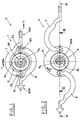
- the reference numeral 1 indicates a device for closing articles, e.g. clothing, leatherwear in general, rucksacks and the like.
- the closing device is composed of: a first half-shell 9, e.g. disk-like, first and second arms 8, 7, which are similar in shape and whose inner heads, 80, 70 respectively, are hinged to the first shell 9, so that the first and the second arms extend in opposite directions and can rotate about a first and second rotation axis Z1, Z2, respectively ( Figure 3).
- an outer head 800 of the first arm 8 is such that it can be fastened, e.g. by a stitching U, to a corresponding first article A1 ( Figures 4a, 4b), and the shape of an outer head 700 of the second arm 7 is such that the head can be hooked to a engagement element S, e.g. a ring, of a corresponding second article A2, or anchored somehow to the article.
- a engagement element S e.g. a ring
- the inner heads 80, 70 of said first and second arms 8, 7 are in mutual engagement with an element O and cooperate, in contrast, with elastic means 50 connected to the element O or to the inner heads, so as to define a closing position K ( Figure 1), in which the first and second arms 8, 7 are situated above the first half-shell 9, so that the outer head 700 of the second arm 7 is near to the inner head 80 of the first arm 8 and vice-versa, and an opening position H, in which the first and second arms 8, 7 are rotated about the corresponding axes Z1, Z2 outwards with respect to the first half-shell 9, so as to be oriented longitudinally (arrow W) towards opposite sides.
- a closing position K Figure 1
- the first and second arms 8, 7 are situated above the first half-shell 9, so that the outer head 700 of the second arm 7 is near to the inner head 80 of the first arm 8 and vice-versa
- an opening position H in which the first and second arms 8, 7 are rotated about the corresponding axes Z1, Z2 outwards with respect to the first half-
- the closing device 1 includes also a second half-shell 6, fastened to the first half-shell 9 by known means, e.g. complementary snap fitting means (not shown) suitably made in the inner surfaces of the first and second half-shells 9, 6, screws or, as shown in Figure 3, two pins M, which are coaxial with the first and second rotation axes Z1, Z2.
- known means e.g. complementary snap fitting means (not shown) suitably made in the inner surfaces of the first and second half-shells 9, 6, screws or, as shown in Figure 3, two pins M, which are coaxial with the first and second rotation axes Z1, Z2.
- the pins M define corresponding pivoting pins for the first and second arms 8, 7.
- the second half-shell 6 is fastened to the first half-shell 9 so as to allow the first and second arms 8, 7 to rotate freely and to prevent the latter from vertical oscillation.
- the inner ends 80, 70 are formed by corresponding gear-sectors D1, D2 and the element O, with which the gear sectors are mutually connected, includes a toothed crown 5 situated inside the first half-shell 9, idle with respect thereto.
- the elastic means 50 include a spiral spring 509, whose one end is fastened to the toothed crown 5 in a first point R1, and whose other end is fastened to the inner surface of the first half-shell 9 in a second point R2.
- the first half-shell 9 can feature, made thereon, some pegs, not shown, to which corresponding elastic means, not shown, are connected for defining snap-fit introduction of the pegs into corresponding seats made in the toothed crown in order to lock the opening position H of the device.
- FIG. 5a A first variant of what is shown in Figures 1, 2, is seen in Figures 5, 5a; as it can be seen, the element O includes a toothed crown 2, which is supported, idle, by a pin 29, integral with the inner surface of the first half-shell 9; the above mentioned gear sectors D1, D2 engage with the toothed crown.
- the elastic means 50 include a spiral spring 28, whose one end E1 is fastened, e.g. constrained within an anchorage channel Ca made in the pin 29, and whose other end E2 is introduced and fastened, e.g. fitted, in an anchorage seat Sa made in the upper surface Su of the toothed crown 2.
- FIG. 6a A second variant of what is shown in Figures 1, 2 is seen in Figures 6, 6a; as it can be seen, the element O includes a toothed crown 20, which features in its central part, a stem 209, protruding axially from the lower surface Si of the crown 20, complementary to a seat 208 made in the first half-shell 9.
- the upper surface Sr of the toothed crown 20 features two parallel flat extensions 290a, 290b, e.g. integral with the surface Sr and situated in a central position with respect thereto, defining an anchoring channel C2.
- the elastic means 50 include a spiral spring 280, whose one end is fastened, e.g. fitted within the anchorage channel C2, and whose other end E2 is introduced and fastened, e.g. fitted, in an anchorage seat S2 made in the inner surface of the second half-shell 6.
- the second half-shell 6 includes a recess 27 made in the inner surface thereof, which houses, due to the coupling of the first half-shell 9 and second half-shell 6, the elastic means 50.
- the device for closing articles is used in the following way.
- the closing device is in closing position K, where the outer end of the first arm 8 is secured to the first article Al, e.g. one side of a coat, or to a rucksack flap, and the hooking element S is fastened to the second article A2, the other side of the coat, or to the fore surface of the rucksack.
- the user grips the outer end 700 of the second arm 7 and drives it to a rotatory-translational motion Y - Y1 ( Figure 1), to contrast the action of the elastic means 50, while pulling at the same time the end toward the engagement element S.
- Rotation of the second arm 7 determines the rotation of the toothed crown 5, 2, 20, and consequently, loading of the spiral spring 509, 28, 280, since it is fastened.
- the device for closing articles e.g. articles of clothing, leatherwear in general, rucksacks and the like is simple to use, aesthetically pleasant and alternative to what is found on the marketplace.
- the device is very functional, because it stabilizes the mutual position of a first and second article Al, A2 and maintains them closed.
- the elastic means 50 include a spiral spring 509, which is fastened in two points R1, R2, and loaded at the opening of the first and second arm 8, 7, determines, as a consequence of the arrangement in the opening position H, the return of the first and second arm to the closing position K.
- the fact that the device is composed of two half-shells is advantageous because the half-shell defining the outer part of the device can assume different shapes and thus it can satisfy a high number of aesthetic needs.
- the shape of the device 1, described previously in a detailed way, allows its wise use for closing articles of clothing, in particular coats and/or jackets, as well as for closing leatherwear articles, such as bags, rucksacks, boots and the like.
Landscapes
- Engineering & Computer Science (AREA)
- Textile Engineering (AREA)
- Treatment And Processing Of Natural Fur Or Leather (AREA)
- Purses, Travelling Bags, Baskets, Or Suitcases (AREA)
- Slide Fasteners, Snap Fasteners, And Hook Fasteners (AREA)
- Professional, Industrial, Or Sporting Protective Garments (AREA)
- Closing And Opening Devices For Wings, And Checks For Wings (AREA)
- Gloves (AREA)
- Seal Device For Vehicle (AREA)
- Diaphragms For Electromechanical Transducers (AREA)
- Glass Compositions (AREA)
Claims (13)
- Vorrichtung zum Verschließen von Gegenständen, die folgendes umfaßt:wobei die Vorrichtung dadurch gekennzeichnet ist, daß sie folgendes umfaßt:erste und zweite Arme (8, 7) mit inneren Köpfen (80, 70), die mit der besagten Vorrichtung verbunden sind, und mit einem äußeren Kopf (800) des ersten Armes (8), der derart ausgebildet ist, daß er an einem zugeordneten ersten Gegenstand (A1) befestigbar ist, und mit einem äußeren Kopf (700) des zweiten Armes (7), der derart ausgebildet ist, daß er mit einem Verbindungselement (S) eines zugeordneten zweiten Gegenstandes (A2) gekoppelt werden kann oder an diesem zuletzt erwähnten Gegenstand befestigt werden kann;elastische Mitte! (50) zur elastischen Überwachung der Arbeitsweise der Vorrichtung,wobei die elastischen Mittel (50), mit den beiden Halbschalen (6, 9) und mit dem besagten kronenartigen Element (O) verbunden sind und mit dem besagten kronenartigen Element (O) und den besagten inneren Köpfen (80, 70) derart zusammenwirken, daß sie eine geschlossene Position (K) definieren, in der der besagte erste und der besagte zweite Arm (8, 7) derart zwischen der besagten ersten Halbschale (9) und der besagten zweiten Halbschale (6) positioniert sind, daß der äußere Kopf (700) des zweiten Armes (7) nahe dem inneren Kopf (80) des ersten Armes (8) liegt und umgekehrt, und eine Öffnungsposition (H), in der der besagte erste und der besagte zweite Arm (8, 7), die auf den zugeordneten Achsen (Z1, Z2) in Richtung auf die Außenseite der ersten Halbschale (9) gedreht sind, longitudinal ausgerichtet sind;eine erste Halbschale (9), wobei die inneren Köpfe (80, 70) des besagten ersten und des besagten zweiten Armes (8, 7) derart an der ersten Halbschale (9) angelenkt sind, daß der erste und zweite Arm auf gegenüberliegenden Seiten angeordnet sind und sich um eine jeweils zugeordnete erste und zweite Drehachse (Z1, Z2) drehen können,wenigstens ein mit Zähnen versehenes kronenartiges Element (O), das seinerseits mit den inneren Köpfen (80, 70) des besagten ersten und zweiten Armes (8, 7) verbunden ist;eine zweite Halbschale, (6), die durch Mittel (M) koaxial mit der ersten und zweiten Drehachse (Z1, Z2) an der ersten Halbschale (9) befestigt ist,
eine Drehung (J. Y) der ersten Halbschale (9) und der zweiten Halbschale (6) um die erste Drehachse (Z1), die den Übergang der Vorrichtung von der Schließposition (K) in die Öffnungsposition (H) und umgekehrt bestimmt. - Schließvorrichtung gemäß Anspruch 1, dadurch gekennzeichnet, daß die besagte zweite Halbschale (6) an der besagten ersten Halbschale (9) mittels Drehzapfen (M) befestigt ist, auf denen der besagte erste und der besagte zweite Arm (8, 7) drehbar gehaltert sind.
- Schließvorrichtung gemäß Anspruch 1, dadurch gekennzeichnet, daß die besagten elastischen Mittel mit dem besagten Element (O) verbunden sind.
- Schließvorrichtung gemäß Anspruch 1, dadurch gekennzeichnet, daß die besagten elastischen Mittel (50) mit den inneren Köpfen (80, 70) der besagten ersten und zweiten Arme (8, 7) verbunden sind.
- Schließvorrichtung gemäß Anspruch 1, dadurch gekennzeichnet, daß die besagten Mittel (M) zugeordnete Drehzapfen für die ersten und zweiten Arme (8, 7) bilden.
- Schließvorrichtung gemäß Anspruch 1, dadurch gekennzeichnet, daß die besagten inneren Enden (80, 70) durch Zahnradsektoren (D1, D2) gebildet werden und daß das besagte Element (O), mit dem die Zahnradsektoren verbunden sind, durch eine mit Zähnen versehene Krone 2 (5, 2, 20) gebildet wird, die in der ersten Halbschale (9) angeordnet ist, sich in Bezug auf die letzteren im Leerlauf befindet und die von den besagten elastischen Mitteln (50) beaufschlagt wird.
- Schließvorrichtung gemäß Anspruch 6, dadurch gekennzeichnet, daß die besagte gezahnte Krone (2), die von den besagten elastischen Mitteln (50) beaufschlagt wird, sich im Leerlauf befindet und durch einen Stift (29) unterstützt wird, der integral mit der inneren Oberfläche der ersten Halbschale (9) ausgebildet ist, und dadurch, daß das freie Ende des besagten Stiftes (29) eine darin angeordnete Verankerungsführung (Ca) aufweist.
- Schließvorrichtung gemäß Anspruch 6, dadurch gekennzeichnet, daß die besagte gezahnte Krone (2), die von den besagten elastischen Mitteln (50) beaufschlagt wird, in ihrem unteren Teil einen Ansatz (209) aufweist, der in einem Sitz (208) angeordnet ist, der im Zentrum der besagten ersten Halbschale (9) gebildet ist, und daß die äußere Oberfläche (Sr) des besagten Zahnrades (20) zwei parallele Zähne (290a, 290b) aufweist, die eine Verankerungsführung (C2) bilden.
- Schließvorrichtung gemäß Anspruch 6, dadurch gekennzeichnet, daß die besagten elastischen Mittel aus einer Spiralfeder (509) bestehen, deren eines Ende in einem ersten Punkt (R1) an der gezahnten Krone (5) befestigt ist und deren anderes Ende in einem zweiten Punkt (R2) an der inneren Oberfläche der ersten Halbschale (9) befestigt ist, wobei die besagten Mittel derart ausgebildet sind, daß sie den Übergang von der Öffnungsposition (H) in die geschlossene Position (K) erleichtern und daß sie die letztere verriegeln.
- Schließvorrichtung gemäß Anspruch 7, dadurch gekennzeichnet, daß die besagten elastischen Mitte! (50) aus einer Spiralfeder (28) bestehen, deren eines Ende (E1) innerhalb der besagten Verankerungsführung (Ca) festgesetzt ist, die im Stift (29) ausgebildet ist, und wobei das andere Ende (E2) in einen Verankerungssitz (Sa), der in der oberen Oberfläche (Su) der besagten gezahnten Krone (2) angeordnet ist, eingesetzt und in diesem befestigt ist, wobei die besagten Mittel derart ausgebildet sind, daß sie den Übergang von der Öffnungsposition (H) in die geschlossene Position (K) erleichtern und daß sie die letztere verriegeln.
- Schließvorrichtung gemäß Anspruch 8, dadurch gekennzeichnet, daß die besagten elastischen Mittel (50) aus einer Spiralfeder (208) bestehen, deren eines Ende (E3) innerhalb der besagten Verankerungsführung (C2) festgesetzt ist, und deren anderes Ende (E4) in einen Verankerungssitz (S2), der in der inneren Oberfläche der zweiten Halbschale (6) angeordnet ist, eingesetzt und in diesem befestigt ist, wobei die besagten Mittel derart ausgebildet sind, daß sie den Übergang von der Öffnungsposition (H) in die geschlossene Position (K) erleichtern und daß sie die letztere verriegeln.
- Schließvorrichtung gemäß Anspruch 6, dadurch gekennzeichnet, daß sie eine Anzahl von Zapfen aufweist, die auf der ersten Halbschale (9) für den Anschluß zugeordneter elastischer Mittel angeordnet sind, welche dazu dienen, eine Schnappverbindung der besagten Zapfen mit zugeordneten Aufnahmen zu bilden, die in der besagten gezahnten Krone (5) angeordnet sind, um wenigstens die Öffnungsposition (H) der besagten Vorrichtung zu verriegeln.
- Schließvorrichtung gemäß Anspruch 6, dadurch gekennzeichnet, daß sie eine Anzahl von Zapfen aufweist, die auf der besagten gezahnten Krone (5) für den Anschluß zugeordneter elastischer Mitte! angeordnet sind, welche dazu dienen, eine Schnappverbindung der besagten Zapfen mit zugeordneten Aufnahmen zu bilden, die in der besagten ersten Halbschale (9) angeordnet sind, um wenigstens die Öffnungsposition (H) der besagten Vorrichtung zu verriegeln.
Applications Claiming Priority (2)
| Application Number | Priority Date | Filing Date | Title |
|---|---|---|---|
| ITBO20010593 | 2001-09-26 | ||
| IT2001BO000593A ITBO20010593A1 (it) | 2001-09-26 | 2001-09-26 | Dispositivo di chiusura di articoli, in particolare capi di abbigliamento e pelletteria in genere |
Publications (2)
| Publication Number | Publication Date |
|---|---|
| EP1297759A1 EP1297759A1 (de) | 2003-04-02 |
| EP1297759B1 true EP1297759B1 (de) | 2005-05-04 |
Family
ID=11439638
Family Applications (1)
| Application Number | Title | Priority Date | Filing Date |
|---|---|---|---|
| EP02021717A Expired - Lifetime EP1297759B1 (de) | 2001-09-26 | 2002-09-25 | Verschlusseinrichtung |
Country Status (4)
| Country | Link |
|---|---|
| EP (1) | EP1297759B1 (de) |
| AT (1) | ATE294516T1 (de) |
| DE (1) | DE60203977T2 (de) |
| IT (1) | ITBO20010593A1 (de) |
Family Cites Families (1)
| Publication number | Priority date | Publication date | Assignee | Title |
|---|---|---|---|---|
| JP3360256B2 (ja) * | 1999-09-17 | 2002-12-24 | モリト株式会社 | 調節用鉤ホック |
-
2001
- 2001-09-26 IT IT2001BO000593A patent/ITBO20010593A1/it unknown
-
2002
- 2002-09-25 DE DE60203977T patent/DE60203977T2/de not_active Expired - Fee Related
- 2002-09-25 AT AT02021717T patent/ATE294516T1/de not_active IP Right Cessation
- 2002-09-25 EP EP02021717A patent/EP1297759B1/de not_active Expired - Lifetime
Also Published As
| Publication number | Publication date |
|---|---|
| ATE294516T1 (de) | 2005-05-15 |
| DE60203977T2 (de) | 2006-01-19 |
| ITBO20010593A1 (it) | 2003-03-26 |
| DE60203977D1 (de) | 2005-06-09 |
| EP1297759A1 (de) | 2003-04-02 |
Similar Documents
| Publication | Publication Date | Title |
|---|---|---|
| US11589655B2 (en) | Buckle | |
| AU2016296619B2 (en) | Interlocking zipper pull tabs and fastening system | |
| EP3533353B1 (de) | Verriegelungsschieberklip | |
| JP4610615B2 (ja) | 物品の紐端固着部位変更具 | |
| US8209822B2 (en) | Draw cord adjuster | |
| US3967708A (en) | Luggage case | |
| US3798715A (en) | Slider assembly for slide fastener | |
| US5642558A (en) | Jewelry clasp | |
| EP0343637B1 (de) | Schlüsselhalter | |
| EP1297759B1 (de) | Verschlusseinrichtung | |
| US6553636B1 (en) | Jewelry clamp | |
| US10945547B2 (en) | Dressing aid | |
| JP2002212805A (ja) | 乳房カップを有する衣料 | |
| US5435045A (en) | Tension fastener for use with backpacks and the like | |
| US5797171A (en) | Buckleless belt | |
| US2859501A (en) | Interchangeable button | |
| US10111479B2 (en) | Method of securing fabric in a decorative manner | |
| US2200147A (en) | Purse | |
| US20170231334A1 (en) | Jewelry Clasp | |
| EP0208661A1 (de) | Schnalle für Riemen und Gurtbänder | |
| WO2024044034A1 (en) | Detachable two way zipper | |
| JP3086362U (ja) | 変芯釦 | |
| US20100281596A1 (en) | Child garment and restraining device | |
| PH26307A (en) | Key holder | |
| JERMYN | Snap Swivel Hook Assembly Incorporating Ball Swivel and Recessed Hook Latch Release Mechanism(Patent) |
Legal Events
| Date | Code | Title | Description |
|---|---|---|---|
| PUAI | Public reference made under article 153(3) epc to a published international application that has entered the european phase |
Free format text: ORIGINAL CODE: 0009012 |
|
| AK | Designated contracting states |
Kind code of ref document: A1 Designated state(s): AT BE BG CH CY CZ DE DK EE ES FI FR GB GR IE IT LI LU MC NL PT SE SK TR |
|
| AX | Request for extension of the european patent |
Extension state: AL LT LV MK RO SI |
|
| 17P | Request for examination filed |
Effective date: 20030922 |
|
| AKX | Designation fees paid |
Designated state(s): AT BE BG CH CY CZ DE DK EE ES FI FR GB GR IE IT LI LU MC NL PT SE SK TR |
|
| AXX | Extension fees paid |
Extension state: RO Payment date: 20030922 |
|
| 17Q | First examination report despatched |
Effective date: 20040226 |
|
| GRAP | Despatch of communication of intention to grant a patent |
Free format text: ORIGINAL CODE: EPIDOSNIGR1 |
|
| GRAP | Despatch of communication of intention to grant a patent |
Free format text: ORIGINAL CODE: EPIDOSNIGR1 |
|
| GRAS | Grant fee paid |
Free format text: ORIGINAL CODE: EPIDOSNIGR3 |
|
| GRAA | (expected) grant |
Free format text: ORIGINAL CODE: 0009210 |
|
| AK | Designated contracting states |
Kind code of ref document: B1 Designated state(s): AT BE BG CH CY CZ DE DK EE ES FI FR GB GR IE IT LI LU MC NL PT SE SK TR |
|
| AX | Request for extension of the european patent |
Extension state: RO |
|
| PG25 | Lapsed in a contracting state [announced via postgrant information from national office to epo] |
Ref country code: NL Free format text: LAPSE BECAUSE OF FAILURE TO SUBMIT A TRANSLATION OF THE DESCRIPTION OR TO PAY THE FEE WITHIN THE PRESCRIBED TIME-LIMIT Effective date: 20050504 Ref country code: CH Free format text: LAPSE BECAUSE OF FAILURE TO SUBMIT A TRANSLATION OF THE DESCRIPTION OR TO PAY THE FEE WITHIN THE PRESCRIBED TIME-LIMIT Effective date: 20050504 Ref country code: SK Free format text: LAPSE BECAUSE OF FAILURE TO SUBMIT A TRANSLATION OF THE DESCRIPTION OR TO PAY THE FEE WITHIN THE PRESCRIBED TIME-LIMIT Effective date: 20050504 Ref country code: LI Free format text: LAPSE BECAUSE OF FAILURE TO SUBMIT A TRANSLATION OF THE DESCRIPTION OR TO PAY THE FEE WITHIN THE PRESCRIBED TIME-LIMIT Effective date: 20050504 Ref country code: AT Free format text: LAPSE BECAUSE OF FAILURE TO SUBMIT A TRANSLATION OF THE DESCRIPTION OR TO PAY THE FEE WITHIN THE PRESCRIBED TIME-LIMIT Effective date: 20050504 Ref country code: FI Free format text: LAPSE BECAUSE OF FAILURE TO SUBMIT A TRANSLATION OF THE DESCRIPTION OR TO PAY THE FEE WITHIN THE PRESCRIBED TIME-LIMIT Effective date: 20050504 Ref country code: TR Free format text: LAPSE BECAUSE OF FAILURE TO SUBMIT A TRANSLATION OF THE DESCRIPTION OR TO PAY THE FEE WITHIN THE PRESCRIBED TIME-LIMIT Effective date: 20050504 Ref country code: CZ Free format text: LAPSE BECAUSE OF FAILURE TO SUBMIT A TRANSLATION OF THE DESCRIPTION OR TO PAY THE FEE WITHIN THE PRESCRIBED TIME-LIMIT Effective date: 20050504 Ref country code: BE Free format text: LAPSE BECAUSE OF FAILURE TO SUBMIT A TRANSLATION OF THE DESCRIPTION OR TO PAY THE FEE WITHIN THE PRESCRIBED TIME-LIMIT Effective date: 20050504 Ref country code: EE Free format text: LAPSE BECAUSE OF FAILURE TO SUBMIT A TRANSLATION OF THE DESCRIPTION OR TO PAY THE FEE WITHIN THE PRESCRIBED TIME-LIMIT Effective date: 20050504 |
|
| REG | Reference to a national code |
Ref country code: GB Ref legal event code: FG4D |
|
| REG | Reference to a national code |
Ref country code: CH Ref legal event code: EP |
|
| REG | Reference to a national code |
Ref country code: IE Ref legal event code: FG4D |
|
| REF | Corresponds to: |
Ref document number: 60203977 Country of ref document: DE Date of ref document: 20050609 Kind code of ref document: P |
|
| PG25 | Lapsed in a contracting state [announced via postgrant information from national office to epo] |
Ref country code: GR Free format text: LAPSE BECAUSE OF FAILURE TO SUBMIT A TRANSLATION OF THE DESCRIPTION OR TO PAY THE FEE WITHIN THE PRESCRIBED TIME-LIMIT Effective date: 20050804 Ref country code: SE Free format text: LAPSE BECAUSE OF FAILURE TO SUBMIT A TRANSLATION OF THE DESCRIPTION OR TO PAY THE FEE WITHIN THE PRESCRIBED TIME-LIMIT Effective date: 20050804 Ref country code: BG Free format text: LAPSE BECAUSE OF FAILURE TO SUBMIT A TRANSLATION OF THE DESCRIPTION OR TO PAY THE FEE WITHIN THE PRESCRIBED TIME-LIMIT Effective date: 20050804 Ref country code: DK Free format text: LAPSE BECAUSE OF FAILURE TO SUBMIT A TRANSLATION OF THE DESCRIPTION OR TO PAY THE FEE WITHIN THE PRESCRIBED TIME-LIMIT Effective date: 20050804 |
|
| PG25 | Lapsed in a contracting state [announced via postgrant information from national office to epo] |
Ref country code: ES Free format text: LAPSE BECAUSE OF FAILURE TO SUBMIT A TRANSLATION OF THE DESCRIPTION OR TO PAY THE FEE WITHIN THE PRESCRIBED TIME-LIMIT Effective date: 20050815 |
|
| PG25 | Lapsed in a contracting state [announced via postgrant information from national office to epo] |
Ref country code: CY Free format text: LAPSE BECAUSE OF FAILURE TO SUBMIT A TRANSLATION OF THE DESCRIPTION OR TO PAY THE FEE WITHIN THE PRESCRIBED TIME-LIMIT Effective date: 20050925 |
|
| PG25 | Lapsed in a contracting state [announced via postgrant information from national office to epo] |
Ref country code: IE Free format text: LAPSE BECAUSE OF NON-PAYMENT OF DUE FEES Effective date: 20050926 |
|
| PG25 | Lapsed in a contracting state [announced via postgrant information from national office to epo] |
Ref country code: MC Free format text: LAPSE BECAUSE OF NON-PAYMENT OF DUE FEES Effective date: 20050930 Ref country code: LU Free format text: LAPSE BECAUSE OF NON-PAYMENT OF DUE FEES Effective date: 20050930 |
|
| PG25 | Lapsed in a contracting state [announced via postgrant information from national office to epo] |
Ref country code: PT Free format text: LAPSE BECAUSE OF FAILURE TO SUBMIT A TRANSLATION OF THE DESCRIPTION OR TO PAY THE FEE WITHIN THE PRESCRIBED TIME-LIMIT Effective date: 20051017 |
|
| NLV1 | Nl: lapsed or annulled due to failure to fulfill the requirements of art. 29p and 29m of the patents act | ||
| REG | Reference to a national code |
Ref country code: CH Ref legal event code: PL |
|
| PLBE | No opposition filed within time limit |
Free format text: ORIGINAL CODE: 0009261 |
|
| STAA | Information on the status of an ep patent application or granted ep patent |
Free format text: STATUS: NO OPPOSITION FILED WITHIN TIME LIMIT |
|
| ET | Fr: translation filed | ||
| 26N | No opposition filed |
Effective date: 20060207 |
|
| REG | Reference to a national code |
Ref country code: IE Ref legal event code: MM4A |
|
| PGFP | Annual fee paid to national office [announced via postgrant information from national office to epo] |
Ref country code: FR Payment date: 20060913 Year of fee payment: 5 |
|
| PGFP | Annual fee paid to national office [announced via postgrant information from national office to epo] |
Ref country code: DE Payment date: 20060928 Year of fee payment: 5 Ref country code: GB Payment date: 20060928 Year of fee payment: 5 |
|
| PGFP | Annual fee paid to national office [announced via postgrant information from national office to epo] |
Ref country code: IT Payment date: 20070928 Year of fee payment: 6 |
|
| GBPC | Gb: european patent ceased through non-payment of renewal fee |
Effective date: 20070925 |
|
| PG25 | Lapsed in a contracting state [announced via postgrant information from national office to epo] |
Ref country code: DE Free format text: LAPSE BECAUSE OF NON-PAYMENT OF DUE FEES Effective date: 20080401 |
|
| REG | Reference to a national code |
Ref country code: FR Ref legal event code: ST Effective date: 20080531 |
|
| PG25 | Lapsed in a contracting state [announced via postgrant information from national office to epo] |
Ref country code: FR Free format text: LAPSE BECAUSE OF NON-PAYMENT OF DUE FEES Effective date: 20071001 |
|
| PG25 | Lapsed in a contracting state [announced via postgrant information from national office to epo] |
Ref country code: GB Free format text: LAPSE BECAUSE OF NON-PAYMENT OF DUE FEES Effective date: 20070925 |
|
| PG25 | Lapsed in a contracting state [announced via postgrant information from national office to epo] |
Ref country code: IT Free format text: LAPSE BECAUSE OF NON-PAYMENT OF DUE FEES Effective date: 20080925 |