EP1297995A1 - Kindersitz - Google Patents
Kindersitz Download PDFInfo
- Publication number
- EP1297995A1 EP1297995A1 EP02021549A EP02021549A EP1297995A1 EP 1297995 A1 EP1297995 A1 EP 1297995A1 EP 02021549 A EP02021549 A EP 02021549A EP 02021549 A EP02021549 A EP 02021549A EP 1297995 A1 EP1297995 A1 EP 1297995A1
- Authority
- EP
- European Patent Office
- Prior art keywords
- belt
- seat portion
- restraint
- seat
- back portion
- Prior art date
- Legal status (The legal status is an assumption and is not a legal conclusion. Google has not performed a legal analysis and makes no representation as to the accuracy of the status listed.)
- Withdrawn
Links
Images


Classifications
-
- B—PERFORMING OPERATIONS; TRANSPORTING
- B60—VEHICLES IN GENERAL
- B60N—SEATS SPECIALLY ADAPTED FOR VEHICLES; VEHICLE PASSENGER ACCOMMODATION NOT OTHERWISE PROVIDED FOR
- B60N2/00—Seats specially adapted for vehicles; Arrangement or mounting of seats in vehicles
- B60N2/02—Seats specially adapted for vehicles; Arrangement or mounting of seats in vehicles the seat or part thereof being movable, e.g. adjustable
- B60N2/04—Seats specially adapted for vehicles; Arrangement or mounting of seats in vehicles the seat or part thereof being movable, e.g. adjustable the whole seat being movable
- B60N2/06—Seats specially adapted for vehicles; Arrangement or mounting of seats in vehicles the seat or part thereof being movable, e.g. adjustable the whole seat being movable slidable
-
- B—PERFORMING OPERATIONS; TRANSPORTING
- B60—VEHICLES IN GENERAL
- B60N—SEATS SPECIALLY ADAPTED FOR VEHICLES; VEHICLE PASSENGER ACCOMMODATION NOT OTHERWISE PROVIDED FOR
- B60N2/00—Seats specially adapted for vehicles; Arrangement or mounting of seats in vehicles
- B60N2/24—Seats specially adapted for vehicles; Arrangement or mounting of seats in vehicles for particular purposes or particular vehicles
- B60N2/26—Seats specially adapted for vehicles; Arrangement or mounting of seats in vehicles for particular purposes or particular vehicles for children
- B60N2/28—Seats readily mountable on, and dismountable from, existing seats or other parts of the vehicle
- B60N2/2803—Adaptations for seat belts
- B60N2/2812—Adaptations for seat belts for securing the child to the child seat
-
- B—PERFORMING OPERATIONS; TRANSPORTING
- B60—VEHICLES IN GENERAL
- B60N—SEATS SPECIALLY ADAPTED FOR VEHICLES; VEHICLE PASSENGER ACCOMMODATION NOT OTHERWISE PROVIDED FOR
- B60N2/00—Seats specially adapted for vehicles; Arrangement or mounting of seats in vehicles
- B60N2/24—Seats specially adapted for vehicles; Arrangement or mounting of seats in vehicles for particular purposes or particular vehicles
- B60N2/26—Seats specially adapted for vehicles; Arrangement or mounting of seats in vehicles for particular purposes or particular vehicles for children
- B60N2/28—Seats readily mountable on, and dismountable from, existing seats or other parts of the vehicle
- B60N2/2821—Seats readily mountable on, and dismountable from, existing seats or other parts of the vehicle having a seat and a base part
-
- B—PERFORMING OPERATIONS; TRANSPORTING
- B60—VEHICLES IN GENERAL
- B60N—SEATS SPECIALLY ADAPTED FOR VEHICLES; VEHICLE PASSENGER ACCOMMODATION NOT OTHERWISE PROVIDED FOR
- B60N2/00—Seats specially adapted for vehicles; Arrangement or mounting of seats in vehicles
- B60N2/24—Seats specially adapted for vehicles; Arrangement or mounting of seats in vehicles for particular purposes or particular vehicles
- B60N2/26—Seats specially adapted for vehicles; Arrangement or mounting of seats in vehicles for particular purposes or particular vehicles for children
- B60N2/28—Seats readily mountable on, and dismountable from, existing seats or other parts of the vehicle
- B60N2/2857—Seats readily mountable on, and dismountable from, existing seats or other parts of the vehicle characterised by the peculiar orientation of the child
- B60N2/286—Seats readily mountable on, and dismountable from, existing seats or other parts of the vehicle characterised by the peculiar orientation of the child forward facing
Definitions
- the present invention relates to a child seat in which a slope of a back portion is changed with a motion of a seat portion in a longitudinal direction.
- a child seat provided with a reclining mechanism for adjusting an angle of the back portion has been conventionally put to practical use.
- Various kinds of structures are proposed as the reclining mechanism.
- a reclining mechanism having a structure in which the rear end part of a seat portion is pivotally connected to the lower end part of a back portion, and the seat portion is provided so as to be movable in the longitudinal direction together with the lower end part of the back portion to thereby change the slope of the back portion.
- a restraint belt is once drawn out from a restraint position on the upper surface side of the seat portion (that is, a restraint position on a sitter side) to the rear side of the back portion with passing through the back portion, and is arranged in such a manner that the belt is closely attached to both of the back surface of the back portion and the lower surface of the seat portion and is restrained at a restraint position on the front end of the seat portion. Accordingly, when changing the angle of the backportion, a distance between the restraint positions with respect to the restraint belt is changed, and there is a possibility that the belt comes short and tends to be tightened with laying the back portion down.
- the seat portion goes up in accordance with a forward movement of the seat portion due to a slope of a seat surface of a vehicle on which the child seat is placed, and a restraint condition for a sitter is changed according to that movement. Accordingly, there is a possibility that an impact resistance becomes unstable.
- an object of the present invention is to provide a child seat which can inhibit a restraint condition from being changed in the case of changing a seat portion and a back portion in an interlocking manner.
- a child seat comprising: a main body; a seat portion which is supported by the main body so as to be movable in a longitudinal direction; a back portion which is connected to the main body so as to be pivotally around an axis in a lateral direction and be movable within a predetermined range in a direction orthogonal to the axis, and which is pivotally connected to a rear end part of the seat portion on a lower end side thereof; a restraint belt which is drawn out to a rear side of the back portion from a restraint position on an upper surface side of the seat portion through the back portion, and which is extended to a restraint position on a front end part of the seat portion via a lower surface side of the seat portion; and a belt position regulating device for moving the restraint belt which is arranged around the rear end part of the seat portion backward from the back surface of the back portion.
- the restraint belt is backward apart from the pivotal center between the seat portion and the back portion, a required length of the restraint belt is reduced in the rear side of the back portion as the back portion is reclined.
- the short of the belt length at a time of reclining the back portion is compensated, and it is possible to inhibit the restraint condition of the belt from being changed as a whole, or it is possible to cancel the change of the restraint condition.
- the main body may be provided with a belt holding device which is in contact with the restraint belt at a time when the seat portion moves forward to a predetermined position, and holds the restraint belt at a fixed position with respect to the main body regardless of a further forward movement of the seat portion.
- a belt holding device which is in contact with the restraint belt at a time when the seat portion moves forward to a predetermined position, and holds the restraint belt at a fixed position with respect to the main body regardless of a further forward movement of the seat portion.
- the belt position regulating device may be provided in the seat portion. In this case, there can be obtained an advantage that the position at which the belt position regulating device and the restraint belt are in contact with each other is not affected by the change in the slope of the back portion.
- the seat portion may be supported to the main body via parallel linkmechanism.
- the seat surface on which the main body is mounted is inclined obliquely, it is possible to longitudinally move the seat portion while keeping the height thereof constant. Accordingly, together with the effect of inhibiting the change of the belt length mentioned above, it is possible to securely inhibit the change of the restraint condition of the sitter and it is possible to stabilize the impact resistance without relation to the slope of the back portion.
- the belt position regulating device may keep a position of the restraint belt in such a manner that a change of a length of the restraint belt required between the restraint position on the upper surface side of the seat portion and an insertion hole of the back portion through which the restraint belt passes is counterbalanced with a change of a length of the restraint belt between the insertion hole and a position at which the belt abuts the belt position regulating device regardless of a reclining motion of the back portion.
- the restraint belt is an assembly of a pair of shoulder belts and an adjust belt
- one end of each shoulder belt is fixed to the seat portion while another end of each shoulder belt is connected to one end of the adjust belt on a rear side of the back portion
- the adjust belt is arranged around the rear end part of the seat portion and is extended along a lower surface of the seat portion
- another end of the adjust belt is drawn out forward from the front end part of the seat portion via an adjuster which inhibits a backward returning motion of the adjust belt to thereby restrain the adjust belt.
- the belt position regulating device may be brought into contact with the adjust belt.
- the main body may be capable of being fixed to a seat of a vehicle by utilizing a harness of the vehicle.
- a child seat comprising: a main body; a seat portion which is supported by the main body so as to be movable in a longitudinal direction; a back portion which is connected to the main body so as to be pivotable around an axis in a lateral direction and be movable within a predetermined range in a direction orthogonal to the axis, and which is pivotally connected to a rear end part of the seat portion on a lower end side thereof; a restraint belt which is drawn out to a rear side of the back portion from a restraint position on an upper surface side of the seat portion through the back portion, and which is extended to a restraint position on a front end part of the seat portion via a lower surface side of the seat portion; and a belt position regulating device which defines a path of the restraint belt so that the restraint belt drawn out to the rear side gradually goes backward from a virtual line obtained by connecting a connection position between the seat portion and the back portion and a
- the restraint belt moves backward apart from the connection position between the seat portion and the back portion in the rear end part of the seat portion. Accordingly, in the same manner as the child seat mentioned above, the short in the length of the belt at a time of reclining the back portion is compensated, and the change in the restraint condition of the belt is inhibited as a whole or cancelled.
- a child seat comprising: a main body; a seat portion which is supported by the main body so as to be movable in a longitudinal direction; a back portion which is connected to the main body so as to be pivotable around an axis in a lateral direction and be movable within a predetermined range in a direction orthogonal to the axis, and which is pivotally connected to a rear end part of the seat portion on a lower end side thereof; and a restraint belt which is drawn out to a rear side of the back portion from a restraint position on an upper surface side of the seat portion through the back portion, and which is extended to a restraint position on a front end part of the seat portion via a lower surface side of the seat portion, and the seat portion is supported to the main body via a parallel link mechanism.
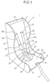
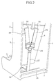
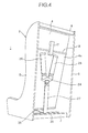
- FIGS. 1 to 3 show a child seat, or a so-called child car seat according to an embodiment of the present invention, in which FIG. 1 is a perspective view from a front surface side, FIG. 2 is a perspective view from a back surface side, and FIG. 3 is a perspective view from a bottom surface side. Also, FIG. 4 shows a state in which a back portion is reclined from a state in FIG. 2.
- a child seat 1 is provided with a main body 2, a seat portion 3 and a back portion 4, each of which is supported on the main body 2, and a harness 20.
- the main body 2 is provided with a pair of side walls 5, and horizontal beams 6, 7 and 8 which connect the side walls 5.
- the main body 2 is generally a resin molded product, however, may be constructed by the other materials.
- the main body 2 is fixed on a seat of a vehicle by utilizing a harness, or a seat belt thereof. Grooves, through holes and the like for passing the harness of the vehicle therethrough are formed in the main body 2, however, an illustration thereof is omitted.
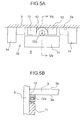
- FIG. 5A is a view which shows a state of the guide mechanism 10 as seen from an inner side of the side wall 5
- FIG. 5B is a cross sectional view along a line Vb-Vb in FIG. 5A.
- rails 11 are provided on both inner surface sides of the side walls 5. In this case, only one rail 11 provided on one inner surface side is shown in FIG. 3, and the other rail 11 provided on the other inner surface side is hidden behind the side wall 5.
- a guide device 12 comprising a roller 12a for making movement smooth and holding members 13 for holding the guide device 12 in a longitudinal direction.
- the roller 12a can roll on the rail 11, and the seat portion 3 is guided in the longitudinal direction owing to the rolling motion of the roller 12a.
- stoppers 14 On the inner surface of the side wall 5, there are mounted stoppers 14 which are brought into contact with the holding members 13 to thereby define a moving range of the seat portion 3.
- protruding portions 15...15 are suitably provided on the inner side of the side wall 5.
- the protruding portion 15...15 are brought into contact with an upper surface of the seat portion 3 to thereby prevent the seat portion 3 from floating up.
- a moving direction of the seat portion 3 may be made parallel to the lower end of the main body 2, or may be obliquely inclined with respect to the lower end of the main body 2.
- the roller 2a is not always required, but the structure may be made without the roller 12a.
- connection portion 17 is provided on a back surface 4a of the back portion 4.
- connection portion 17a there is formed a slotted hole 17a extending substantially in a vertical direction, and a rod 18 is inserted through the slotted hole 17a.
- the rod 18 is fixed to the side walls 5 at both ends thereof.
- the back portion 4 is connected to the main body 2 so as to be pivotable around the rod 18 and movable within a predetermined range substantially in the vertical direction along the slotted hole 17a. In this case, a backward load to be applied to the back portion 4 can be supported by the main body 2 via the rod 18.
- the connection portion 17 may be integrally formed with the back portion 4.
- the connection portion 17 may be manufactured in aprocess separate from that of the back portion 4 and may be fixed to the back portion 4 by utilizing fixing means such as bolts, an adhesive agent or the like.
- the harness 20 is constructed by combining a crotch belt 21 and a restraint belt 22.
- the crotch belt 21 is passed the crotch of a sitter, or a person who sits on the seat portion 3, and a lower end of the crotch belt 21 is fixed to a side of the lower surface 3a of the seat portion 3 via a fixing device 23 (refer to FIG. 3).
- a buckle 24 On an upper end of the crotch belt 21, there is mounted a buckle 24 for connecting the restraint belt 22 therewith.
- a pad 25 which receives the sitter is mounted in the middle of the crotch belt 21.
- the restraint belt 22 is an assembly which is structured by connecting a pair of shoulder belts 26 and one adjust belt 27 on a side of the back surface 4a of the back portion 4 through a connecting device 28.
- One end of each shoulder belt 26 is drawn out to a side of the lower surface 3a through the seat portion 3, and is prevented from coming off by a fixing device 29 (refer to FIG. 3).
- another end of each shoulder belt 26 is drawn out to a side of the back surface 4a via a belt insertion hole 30 of the back portion so as to be fixed to the connecting device 28.
- One end of the adjust belt 27 is fixed to the connecting device 28.
- the adjust belt 27 is arranged around the rear end of the seat portion 3 and is extended along the lower surface 3a.
- the adjuster 31 is a well-known holding device which allows the belt 27 to be drawn out forward, and inhibits a backward returning motion of the belt 27 unless a predetermined canceling operation is performed.
- a tongue fitting 32 is mounted to each of the shoulder belts 26.
- the tongue fitting 32 can move along the belt 26.
- the restraint belt 22 and the crotch belt 21 are connected to each other by inserting the respective tongue fittings 32 to the buckle 24 so as to engage with each other.
- a tubular cover 33 is mounted to each of the shoulder belts 26.
- a lock mechanism which holds the seat portion 3 and the back portion 4 at a fixed position is provided in the child seat 1, however, an illustration thereof is omitted.
- the belt length required between the position of the belt insertion hole 30 and the restraint position of the belt 22 by the adjuster 31 is kept constant regardless of an angle of the back portion 4.
- the belt length relatively comes short as the back portion 4 is reclined. That is, the restraint condition of the sitter is changed in correspondence to the slope of the back portion 4. Accordingly, there is generated a necessity of loosening the adjuster 31 so as to readjust the belt length between the restraint portions every time when the angle of the back portion 4 is changed.
- a belt position regulating plate 35 which protrudes backward from the back surface 4a of the back portion 4, is provided as a belt position regulating device on the rear end of the lower surface 3a of the seat portion 3, and the restraint belt 22 (the adjust belt 27) is pushed backward from the back surface 4a of the back portion 4 by the belt position regulating plate 35.
- a rod 36 is mounted, as a belt holding device, between the side walls 5.
- a position of the rod 36 is deviated forward from a position of a leading end (a position with which the belt 27 is brought into contact) of the belt position regulating plate 35 at a time of vertically rising the back portion 4 most, that is, at a time of moving the seat portion 3 most backward.
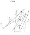
- FIGS. 7A to 7C a path of the restraint belt 22 is shown by a one-dot chain line, and a restraint position of the restraint belt 22 in the seat portion 3, a position of the belt insertion hole 30 and a restraint position by the adjuster 31 are denoted by reference symbols A, B and C, respectively.
- the belt path from the restraint position A to the belt passing position B does not actually become a straight line, however, the belt path is shown by a straight line as a matter of convenience.
- the belt length required between the insertion hole 30 and the contact position between the belt position regulating plate 35 and the restraint belt 22 is reduced as the back portion 4 is reclined.
- These changes with respect to the belt length are counterbalanced with each other, whereby the short in length of the belt 22 between the restraint portions is reduced or cancelled.
- the restraint belt 22 is held by the rod 36 and is away from the belt position regulating plate 35 (refer to FIG. 4). Accordingly, it is possible to limit the effect applied by the belt position regulating plate 35 within a proper range.
- a point A shows a restraint position of the restraint belt 22 with respect to the seat portion 3 by the fixing device 29
- points B and B' show positions at which the restraint belt 22 passes through the belt insertion hole 30 of the back portion 4
- a point E shows a center of rotation of the hinge 16 which connects the seat portion 3 and the back portion 4 to each other
- a point F shows a restraint position of the belt 22 by the belt position regulating plate 35, respectively.
- a slope of the back portion 4 at a time of rising is represented by a line segment BE
- a slope of the back portion 4 at a time of reclining is represented by a line segment B'E.
- the belt lengths from the restraint position A to the belt passing positions B and B' can be represented by line segments AB and AB', respectively.
- a distance from the center of rotation of the hinge 16 to the belt insertion hole 30 is constant regardless of the slope of the back portion 4, and lengths of the line segments EB and EB' are equal to each other. Accordingly, a length of the line segment AB' is greater than that of the line segment AB. This means that the required length of the belt 22 is increased in the front surface side of the back portion 4 as the back portion 4 is reclined.
- the distance x can be given by the following formula (1).
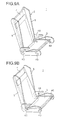
- FIGS. 9A and 9B show an embodiment in which the guide mechanism 10 of the seat portion 3 is modified.
- each of the side walls 5 of the main body and the seat portion 3 are connected via a pair of front and rear parallel links 40, which form a parallel link mechanism.
- the parallel links 40 it is possible to move the seat portion 3 longitudinally while keeping the height of the seat portion 3 (in this case, an absolute height from a ground plane of the vehicle) constant, for example, even when a seat surface 50 of the vehicle is inclined obliquely as shown in FIG. 10.
- one end of the restraint belt 22 is fixed to the side of the lower surface of the seat portion 3, and the tongue fitting 32 which is movably provided on the restraint belt 22 is connected to the buckle 24.
- the present invention is not limited to the aspects mentioned above.
- the present invention can be applied to the child seat structured such that a tongue fitting is mounted to the front end of the restraint belt 22, and the tongue fitting is connected to the buckle fixed to the seat portion 3.
- the belt position regulating plate 35 is provided in the lower surface 3a of the seat portion 3, however, the belt position regulating device may be provided in the back portion 4.
- the effect according to the present invention can be achieved as far as the restraint belt 22 is guided in such a manner that the restraint belt 20 is backward away from a virtual line (corresponding to the line segments BE and B' E in FIG. 8) obtained by connecting the belt insertion hole 30 and the rotation center of the hinge 16 to each other as the restraint belt 22 drawn out from the belt insertion hole 30 to the side of the back surface 4a goes downward. Therefore, at least the opposing portion to the belt 22 in the back surface 4a of the back portion 4 may be protruded backward as the opposing portion goes to the lower part thereof, thereby closely attaching the protruding portion to the belt 22.
- a virtual line corresponding to the line segments BE and B' E in FIG. 8
- the illustrated shapes of the seat portion 3 and the back portion 4 correspond to one example, and can be suitably modified.
- the present invention it is possible to counterbalanced the changes of the required belt lengths in the front surface side and in the back surface side of the back portion with each other at a time of changing the slope of the back portion, by making the restraint belt extending around the rear end of the seat portion be backward away from the connection position between the seat portion and the back portion. Further, it is possible to move the seat portion longitudinally while keeping the height of the seat surface substantially constant by supporting the seat portion to the main body via the parallel links. Accordingly, it is possible to inhibit the change in the restraint condition of the sitter at a time of displacing the seat portion and the back portion in an interlocking manner.
Landscapes
- Engineering & Computer Science (AREA)
- Aviation & Aerospace Engineering (AREA)
- Transportation (AREA)
- Mechanical Engineering (AREA)
- Health & Medical Sciences (AREA)
- Child & Adolescent Psychology (AREA)
- General Health & Medical Sciences (AREA)
- Seats For Vehicles (AREA)
- Automotive Seat Belt Assembly (AREA)
- Chairs For Special Purposes, Such As Reclining Chairs (AREA)
Applications Claiming Priority (2)
| Application Number | Priority Date | Filing Date | Title |
|---|---|---|---|
| JP2001297928A JP4884620B2 (ja) | 2001-09-27 | 2001-09-27 | チャイルドシート |
| JP2001297928 | 2001-09-27 |
Publications (1)
| Publication Number | Publication Date |
|---|---|
| EP1297995A1 true EP1297995A1 (de) | 2003-04-02 |
Family
ID=19118916
Family Applications (1)
| Application Number | Title | Priority Date | Filing Date |
|---|---|---|---|
| EP02021549A Withdrawn EP1297995A1 (de) | 2001-09-27 | 2002-09-26 | Kindersitz |
Country Status (6)
| Country | Link |
|---|---|
| US (1) | US6808232B2 (de) |
| EP (1) | EP1297995A1 (de) |
| JP (1) | JP4884620B2 (de) |
| KR (1) | KR20030028390A (de) |
| CN (1) | CN1248884C (de) |
| TW (1) | TW593013B (de) |
Cited By (1)
| Publication number | Priority date | Publication date | Assignee | Title |
|---|---|---|---|---|
| ITMO20090116A1 (it) * | 2009-05-06 | 2010-11-07 | Segrall S R L | Seggiolino per trasportare un bambino in un veicolo. |
Families Citing this family (29)
| Publication number | Priority date | Publication date | Assignee | Title |
|---|---|---|---|---|
| DE10251040B4 (de) * | 2002-11-02 | 2010-01-21 | Daimler Ag | Kindersitz |
| TW200520994A (en) * | 2003-12-05 | 2005-07-01 | Combi Corp | Child seat |
| JP4520734B2 (ja) * | 2003-12-05 | 2010-08-11 | コンビ株式会社 | チャイルドシート |
| DE102004046163A1 (de) * | 2004-08-12 | 2006-02-23 | Columbus Trading-Partners Pos und Brendel GbR (vertretungsberechtigte Gesellschafter Karin Brendel, 95503 Hummeltal und Bohumila Pos, 95445 Bayreuth) | Kindersitz für Kraftfahrzeuge |
| DE102005007262A1 (de) * | 2005-02-16 | 2006-08-24 | Recaro Gmbh & Co. Kg | Auto-Kindersitz mit einer Einrichtung zur Verstellung der Neigung des Kindersitzes |
| USD535911S1 (en) * | 2005-09-23 | 2007-01-30 | Crisco David J | Universal child seatbelt |
| WO2010025571A1 (en) * | 2008-09-05 | 2010-03-11 | Magna Marque International Inc. | Adjuster and hinge for child booster seat |
| WO2010058035A1 (en) * | 2008-11-24 | 2010-05-27 | Holmbergs Childsafety Ab | A safety belt buckle and assembly for a vehicle child seat |
| WO2011082553A1 (en) * | 2010-01-11 | 2011-07-14 | Great Fortune (Hk) Limited | An electric furniture frame assembly |
| US8579369B2 (en) | 2010-10-26 | 2013-11-12 | Cosco Management, Inc. | Truss system for juvenile vehicle seat |
| US8585138B2 (en) | 2010-10-26 | 2013-11-19 | Cosco Management, Inc. | Rigidifying system for single shell juvenile vehicle seat |
| US8573693B2 (en) | 2010-12-21 | 2013-11-05 | Cosco Management, Inc. | Adjustable headrest for juvenile vehicle |
| US9022471B2 (en) | 2011-01-07 | 2015-05-05 | Cosco Management, Inc. | Headrest for juvenile vehicle seat |
| US8764108B2 (en) | 2011-03-22 | 2014-07-01 | Cosco Management, Inc. | Adjustable headrest for juvenile vehicle seat |
| CL2012001772A1 (es) * | 2011-07-01 | 2014-06-06 | Wonderland Nursery Goods | Un asiento para un niño que comprende un armazon de asiento con una parte posterior, una banda de anclaje que tiene una porcion intermedia y dos porciones de extremo provistas respectivamente con dos sujetadores operables para fijacion con una estructura de anclaje de un vehiculo, y cierre operable. |
| US9102348B2 (en) * | 2011-11-16 | 2015-08-11 | Wonderland Nurserygoods Company Limited | Baby carriage capable of adjusting recline angle of seat back |
| CN102555856B (zh) * | 2012-01-06 | 2016-03-09 | 好孩子儿童用品有限公司 | 儿童汽车安全座 |
| FR2996501A1 (fr) * | 2012-10-08 | 2014-04-11 | Dorel France Sa | Siege auto pour enfant, a assise reglable en hauteur |
| ES2664929T3 (es) * | 2013-03-13 | 2018-04-24 | BRITAX RÖMER Kindersicherheit GmbH | Asiento de seguridad infantil |
| JP6352018B2 (ja) * | 2014-03-27 | 2018-07-04 | コンビ株式会社 | チャイルドシート |
| JP6366974B2 (ja) * | 2014-03-27 | 2018-08-01 | コンビ株式会社 | チャイルドシート |
| DE202014104056U1 (de) * | 2014-08-29 | 2014-09-19 | Cybex Gmbh | Kindersitz für ein Kraftfahrzeug |
| CN104492002A (zh) * | 2014-12-01 | 2015-04-08 | 江苏九久交通设施有限公司 | 三点背带式安全带 |
| CN104827935A (zh) * | 2015-04-15 | 2015-08-12 | 徐刘恒 | 儿童安全汽车座椅 |
| US10011198B2 (en) | 2016-09-22 | 2018-07-03 | Joshua Hans Theander | Vehicular seating assembly, system and method |
| CN111267692B (zh) * | 2020-02-10 | 2021-01-01 | 延锋安道拓座椅有限公司 | 一种可折叠儿童座椅 |
| WO2022160405A1 (zh) * | 2021-01-29 | 2022-08-04 | 好孩子儿童用品有限公司 | 儿童座位装置及儿童用品 |
| DE202024100144U1 (de) * | 2024-01-12 | 2024-01-29 | Cybex Gmbh | Kinderaufnahmevorrichtung, insbesondere Kinderwagen und/oder Kindersitz, mit einem Gurtsystem |
| IL310158A (en) * | 2024-01-15 | 2025-08-01 | Doona Holdings Ltd | Convertible baby safety car seat assembly |
Citations (3)
| Publication number | Priority date | Publication date | Assignee | Title |
|---|---|---|---|---|
| EP0301281A2 (de) * | 1987-07-29 | 1989-02-01 | VALLKO S.r.l. | Kindersitz, welcher in Kraftfahrzeugen montierbar ist |
| EP0545185A1 (de) * | 1991-12-06 | 1993-06-09 | Kabushiki Kaisha Tokai-Rika-Denki-Seisakusho | Kindersitz |
| EP0554807A2 (de) * | 1992-01-31 | 1993-08-11 | Life Force Associates L.P. | Kindersicherheitssitz |
Family Cites Families (7)
| Publication number | Priority date | Publication date | Assignee | Title |
|---|---|---|---|---|
| US3404917A (en) * | 1966-06-28 | 1968-10-08 | Reynolds Res & Mfg Corp | Mounting bracket for automobile baby seat |
| US4058342A (en) * | 1975-11-14 | 1977-11-15 | Ettridge John P | Child's car seat |
| US4915446A (en) * | 1987-05-26 | 1990-04-10 | Darling Ronald J | Infant seat, removable seat and seat latch |
| JPH02127134A (ja) * | 1988-11-04 | 1990-05-15 | Bridgestone Corp | 車両用子供シート |
| JPH11208332A (ja) * | 1998-01-21 | 1999-08-03 | Takata Kk | チャイルドシート |
| JP4095173B2 (ja) * | 1998-07-28 | 2008-06-04 | デルタ工業株式会社 | 乗物用シート |
| DE19906547B4 (de) * | 1999-02-17 | 2004-03-25 | Innovint Einrichtungs Gmbh | Kindersitz zur mobilen Verwendung in einem Flugzeug |
-
2001
- 2001-09-27 JP JP2001297928A patent/JP4884620B2/ja not_active Expired - Fee Related
-
2002
- 2002-08-29 TW TW091119702A patent/TW593013B/zh not_active IP Right Cessation
- 2002-09-26 KR KR1020020058292A patent/KR20030028390A/ko not_active Withdrawn
- 2002-09-26 US US10/254,977 patent/US6808232B2/en not_active Expired - Fee Related
- 2002-09-26 EP EP02021549A patent/EP1297995A1/de not_active Withdrawn
- 2002-09-27 CN CNB021430845A patent/CN1248884C/zh not_active Expired - Fee Related
Patent Citations (3)
| Publication number | Priority date | Publication date | Assignee | Title |
|---|---|---|---|---|
| EP0301281A2 (de) * | 1987-07-29 | 1989-02-01 | VALLKO S.r.l. | Kindersitz, welcher in Kraftfahrzeugen montierbar ist |
| EP0545185A1 (de) * | 1991-12-06 | 1993-06-09 | Kabushiki Kaisha Tokai-Rika-Denki-Seisakusho | Kindersitz |
| EP0554807A2 (de) * | 1992-01-31 | 1993-08-11 | Life Force Associates L.P. | Kindersicherheitssitz |
Cited By (1)
| Publication number | Priority date | Publication date | Assignee | Title |
|---|---|---|---|---|
| ITMO20090116A1 (it) * | 2009-05-06 | 2010-11-07 | Segrall S R L | Seggiolino per trasportare un bambino in un veicolo. |
Also Published As
| Publication number | Publication date |
|---|---|
| KR20030028390A (ko) | 2003-04-08 |
| US6808232B2 (en) | 2004-10-26 |
| CN1248884C (zh) | 2006-04-05 |
| US20030057753A1 (en) | 2003-03-27 |
| CN1408302A (zh) | 2003-04-09 |
| JP2003104100A (ja) | 2003-04-09 |
| JP4884620B2 (ja) | 2012-02-29 |
| TW593013B (en) | 2004-06-21 |
Similar Documents
| Publication | Publication Date | Title |
|---|---|---|
| EP1297995A1 (de) | Kindersitz | |
| US7000880B2 (en) | Slide for motor vehicle seat | |
| EP0631903B1 (de) | Sicherheitssitz für Kinder in Kraftfahrzeugen und verstellbarer Sitz | |
| US6520588B1 (en) | Seat belt guide | |
| US4790597A (en) | Vehicle seat with a longitudinal guide, with an adjustment of height or inclination, and with an attachment for seat belt lock | |
| US20090174242A1 (en) | Vehicle seat with a seat depth adjustment device | |
| US20090236882A1 (en) | Seat apparatus for vehicle | |
| EP1493615A2 (de) | Kindersitz | |
| US7658443B2 (en) | Inboard buckle attachment for a four-way seat | |
| CN102328603B (zh) | 车辆座椅框架的支撑结构 | |
| US5697674A (en) | Vehicle seat having a seat proper that is adjustable in height | |
| US5411319A (en) | Vehicle seat | |
| US20190308529A1 (en) | Child safety seat | |
| US20060049682A1 (en) | Vehicle rear seat device | |
| US7367630B2 (en) | Integrated seat of an automotive vehicle | |
| US5924731A (en) | Height adjuster for seat belt webbing | |
| EP0952047B1 (de) | Schnalle für einen Sicherheitsgurt | |
| US20250242729A1 (en) | Seat, in particular vehicle seat | |
| JP4521591B2 (ja) | シートバックのフレーム構造 | |
| KR101685028B1 (ko) | 차일드 시트 | |
| US11623607B1 (en) | Vehicle seat assembly | |
| US20060103211A1 (en) | Seat assembly with inner seat back movable with a seat cushion | |
| JP2778401B2 (ja) | シートベルト付きシート | |
| US12036906B2 (en) | Baby changing table assembly for a vehicle | |
| JP5263917B2 (ja) | チャイルドシート |
Legal Events
| Date | Code | Title | Description |
|---|---|---|---|
| PUAI | Public reference made under article 153(3) epc to a published international application that has entered the european phase |
Free format text: ORIGINAL CODE: 0009012 |
|
| AK | Designated contracting states |
Kind code of ref document: A1 Designated state(s): AT BE BG CH CY CZ DE DK EE ES FI FR GB GR IE IT LI LU MC NL PT SE SK TR Designated state(s): AT BE BG CH CY CZ DE DK EE ES FI FR GB GR IE IT LI LU MC NL PT SE SK TR |
|
| AX | Request for extension of the european patent |
Extension state: AL LT LV MK RO SI |
|
| 17P | Request for examination filed |
Effective date: 20030807 |
|
| AKX | Designation fees paid |
Designated state(s): DE ES FR GB IT |
|
| 17Q | First examination report despatched |
Effective date: 20041217 |
|
| GRAP | Despatch of communication of intention to grant a patent |
Free format text: ORIGINAL CODE: EPIDOSNIGR1 |
|
| STAA | Information on the status of an ep patent application or granted ep patent |
Free format text: STATUS: THE APPLICATION IS DEEMED TO BE WITHDRAWN |
|
| 18D | Application deemed to be withdrawn |
Effective date: 20060131 |