EP1298083A1 - Einrichtung zum Sperren einer Fangvorrichtung für eine Aufzugseinrichtung - Google Patents
Einrichtung zum Sperren einer Fangvorrichtung für eine Aufzugseinrichtung Download PDFInfo
- Publication number
- EP1298083A1 EP1298083A1 EP02020343A EP02020343A EP1298083A1 EP 1298083 A1 EP1298083 A1 EP 1298083A1 EP 02020343 A EP02020343 A EP 02020343A EP 02020343 A EP02020343 A EP 02020343A EP 1298083 A1 EP1298083 A1 EP 1298083A1
- Authority
- EP
- European Patent Office
- Prior art keywords
- counterweight
- elevator
- elevator car
- safety gear
- lever
- Prior art date
- Legal status (The legal status is an assumption and is not a legal conclusion. Google has not performed a legal analysis and makes no representation as to the accuracy of the status listed.)
- Granted
Links
Images

Classifications
-
- B—PERFORMING OPERATIONS; TRANSPORTING
- B66—HOISTING; LIFTING; HAULING
- B66B—ELEVATORS; ESCALATORS OR MOVING WALKWAYS
- B66B5/00—Applications of checking, fault-correcting, or safety devices in elevators
- B66B5/02—Applications of checking, fault-correcting, or safety devices in elevators responsive to abnormal operating conditions
- B66B5/16—Braking or catch devices operating between cars, cages, or skips and fixed guide elements or surfaces in hoistway or well
- B66B5/18—Braking or catch devices operating between cars, cages, or skips and fixed guide elements or surfaces in hoistway or well and applying frictional retarding forces
Definitions
- the invention relates to an elevator device with a an elevator car movable with and a counterweight movable in the elevator shaft, whereby the speed of the elevator car or Counterweight by means of a Speed limiter device is monitored and the Speed limiter device at Excess speed of the elevator car or the Counterweight the elevator car or the counterweight stops using a safety gear.
- a disadvantage of the known device is that the elevator car must be released from the catch.
- the Safety gear must be reset and the Checked the guide rails at the catch point and the Surface can be processed.
- the evacuation of the Elevator passengers can only be carried out by specialist staff become.
- the invention seeks to remedy this.
- the invention as characterized in claim 1 solves the problem to avoid the disadvantages of the known device and to create a facility by means of the false triggers the safety gear can be avoided.
- the advantages achieved by the invention are in essential to see in the fact that the Safety gear is not triggered.
- the elevator passengers this will not cause extreme delays in the Elevator cabin suspended.
- the implementation of the Evacuation of elevator passengers no specialist staff necessary.
- the elevator car can be used after the buffer run can be moved manually to the neighboring floor, so that the elevator passengers leave the elevator car can.
- the mechanics of the safety gear and of the speed limiter and the guide rails spared.
- the safety gear is not used for buffer tests triggered the considerable effort to release the catch is spared.
- the safety gear is used for acceptance tests usually blocked, so with unusual Test runs no catch cases in the shaft end areas may occur. With the device according to the invention is security even with acceptance tests over the entire Shaft height guaranteed.
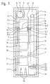
- Fig. 1 shows an elevator device with one in one Elevator shaft 1 movable elevator car 2, the one Rope 3 is connected to a counterweight 4.
- the rope 3 is in operation by means of a traction sheave 5 Drive unit 6 driven.
- Elevator car 2 and Counterweight 4 are by means of the shaft height extending guide rails 7 out.
- the Elevator device has a top floor with a top floor door 8, a second top floor with a second top floor door 9, further floors with further floor doors 10 and a lower floor with a lowest floor door 11.
- a shaft head 12 is the drive unit 6 and a Speed limiter 13 arranged the Speed of elevator car 2 monitored and at The elevator car 2 stops at excessive speed.
- the endless limiter rope 19 is by means of a Pit 20 arranged deflection roller 21 tensioned, wherein a roller axis 22 at one end at a pivot point 23 is articulated and carries a tension weight 24 at the other end.
- a locking lever 25 is at the fulcrum 15 with one Double lever 14 connected.
- the one side 14.1 of a double lever 14 after deflected above.
- the locking lever 25 deflected counterclockwise.
- Fig. 1 shows that started on the top floor Elevator car 2 on the way down, with a stop on the second lowest floor and then on the lowest floor is provided. If, for example the journey from the second lowest floor to the lowest Floor runs with less than overspeed and the elevator car 2 on the lowest floor is not stops, the elevator car 2 will continue on caught below by buffers 26.
- the can Safety gear 16 due to the inertia of the Speed limiter 13 and the governor rope 19 are triggered, the catch elements of the Wedge the safety gear 16 with the guide rails 7.
- At least one locking element 27 is also on the upper one Provided shaft end, if the upper shaft end also Has buffer.
- the Device according to the invention for evacuating Elevator passengers can also access an elevator facility be used with machine room.
- Fig. 2 shows details of the locking lever 25 and Locking element 27 formed locking device for locking the Safety gear 16 during buffer travel.
- the one with the undressed Lock lever 25 shown in line is shown capable where the elevator car is on the bottom floor stands.
- the one shown with a dash-dotted line Locking lever 25 is shown in the position where the Safety gear 16 is engaged.
- the movement of the Locking lever 25 is not by the locking element 27 blocked.
- the one shown with a broken line Locking lever 25 is shown in the position where the Elevator car 2 down the bottom floor has run over.
- the movement of the locking lever 25 will blocked by means of the blocking element 27.
- the movement of the connected to the locking lever 25 at the pivot point 15 Double lever 14 is also blocked. The trigger the safety device 16 is thus prevented.
Landscapes
- Engineering & Computer Science (AREA)
- Mechanical Engineering (AREA)
- Maintenance And Inspection Apparatuses For Elevators (AREA)
Abstract
Description
eine Aufzugseinrichtung mit einer Fangvorrichtung zum Stillsetzen einer Aufzugskabine und
Einzelheiten einer Sperreinrichtung zum Sperren der Fangvorrichtung.
Claims (3)
- Aufzugseinrichtung mit einer in einem Aufzugsschacht verfahrbaren Aufzugskabine und mit einem im Aufzugsschacht verfahrbaren Gegengewicht, wobei die Geschwindigkeit der Aufzugskabine bzw. des Gegengewichtes mittels einer Geschwindigkeitsbegrenzereinrichtung überwacht wird und die Geschwindigkeitsbegrenzereinrichtung bei Übergeschwindigkeit der Aufzugskabine oder des Gegengewichtes die Aufzugskabine bzw. das Gegengewicht mittels einer Fangvorrichtung stillsetzt,
dadurch gekennzeichnet, dass eine Sperreinrichtung (25,27) vorgesehen ist, die bei einer Pufferfahrt der Aufzugskabine (2) oder des Gegengewichtes (4) die Fangvorrichtung (16) sperrt. - Verfahren nach Anspruch 1,
dadurch gekennzeichnet, dass mindestens ein im Aufzugsschacht (1) angeordnetes Sperrelement (27) vorgesehen ist, das die Bewegung eines mit einem Auslösehebelwerk (14,15,17,18) der Fangvorrichtung (16) in Verbindung stehenden Sperrhebels (25) blockiert. - Verfahren nach den Ansprüchen 1 oder 2,
dadurch gekennzeichnet, dass das Sperrelement (27) eine kurvenförmige Bahn aufweist, die einenends die Bewegung des Sperrhebels (25) ermöglicht und anderenends die Bewegung des Sperrhebels (25) blockiert.
Priority Applications (1)
| Application Number | Priority Date | Filing Date | Title |
|---|---|---|---|
| EP20020020343 EP1298083B1 (de) | 2001-09-28 | 2002-09-12 | Einrichtung zum Sperren einer Fangvorrichtung für eine Aufzugseinrichtung |
Applications Claiming Priority (3)
| Application Number | Priority Date | Filing Date | Title |
|---|---|---|---|
| EP01810946 | 2001-09-28 | ||
| EP01810946 | 2001-09-28 | ||
| EP20020020343 EP1298083B1 (de) | 2001-09-28 | 2002-09-12 | Einrichtung zum Sperren einer Fangvorrichtung für eine Aufzugseinrichtung |
Publications (2)
| Publication Number | Publication Date |
|---|---|
| EP1298083A1 true EP1298083A1 (de) | 2003-04-02 |
| EP1298083B1 EP1298083B1 (de) | 2005-11-23 |
Family
ID=26077421
Family Applications (1)
| Application Number | Title | Priority Date | Filing Date |
|---|---|---|---|
| EP20020020343 Expired - Lifetime EP1298083B1 (de) | 2001-09-28 | 2002-09-12 | Einrichtung zum Sperren einer Fangvorrichtung für eine Aufzugseinrichtung |
Country Status (1)
| Country | Link |
|---|---|
| EP (1) | EP1298083B1 (de) |
Cited By (1)
| Publication number | Priority date | Publication date | Assignee | Title |
|---|---|---|---|---|
| US11046552B2 (en) | 2018-03-27 | 2021-06-29 | Otis Elevator Company | Method and system of reducing false actuation of safety brakes in elevator system |
Families Citing this family (3)
| Publication number | Priority date | Publication date | Assignee | Title |
|---|---|---|---|---|
| AU2008359040B2 (en) | 2008-07-11 | 2014-11-06 | Inventio Ag | Catch device with an energy accumulator element |
| EP2226285B1 (de) | 2009-03-06 | 2012-05-30 | Inventio AG | Aufzugskabine mit einer Fangvorrichtung |
| EP2253571A1 (de) | 2009-05-20 | 2010-11-24 | Inventio AG | Aufzugsspannvorrichtung und Aufzugsanlage mit einer solchen Aufzugsspannvorrichtung |
Citations (3)
| Publication number | Priority date | Publication date | Assignee | Title |
|---|---|---|---|---|
| US1581458A (en) * | 1924-07-11 | 1926-04-20 | Otis Elevator Co | Elevator safety appliance |
| JPS59118678A (ja) * | 1982-12-27 | 1984-07-09 | 三菱電機株式会社 | エレベ−タ装置 |
| US5713434A (en) * | 1995-07-07 | 1998-02-03 | Otis Elevator Company | Elevator safety system |
-
2002
- 2002-09-12 EP EP20020020343 patent/EP1298083B1/de not_active Expired - Lifetime
Patent Citations (3)
| Publication number | Priority date | Publication date | Assignee | Title |
|---|---|---|---|---|
| US1581458A (en) * | 1924-07-11 | 1926-04-20 | Otis Elevator Co | Elevator safety appliance |
| JPS59118678A (ja) * | 1982-12-27 | 1984-07-09 | 三菱電機株式会社 | エレベ−タ装置 |
| US5713434A (en) * | 1995-07-07 | 1998-02-03 | Otis Elevator Company | Elevator safety system |
Cited By (1)
| Publication number | Priority date | Publication date | Assignee | Title |
|---|---|---|---|---|
| US11046552B2 (en) | 2018-03-27 | 2021-06-29 | Otis Elevator Company | Method and system of reducing false actuation of safety brakes in elevator system |
Also Published As
| Publication number | Publication date |
|---|---|
| EP1298083B1 (de) | 2005-11-23 |
Similar Documents
| Publication | Publication Date | Title |
|---|---|---|
| DE2753445C2 (de) | ||
| DE69926244T2 (de) | Schachtsicherheitssystem für Aufzug | |
| DE4336150A1 (de) | Aufzugsführungsschienen-Greifvorrichtung | |
| EP0922663B1 (de) | Aufzug, insbesondere Treibscheibenaufzug | |
| EP0440839B2 (de) | Vorrichtung zur Verhinderung unkontrollierter Bewegungen von Aufzügen | |
| DE102010030436A1 (de) | Aufzuganlage | |
| DE102015111754A1 (de) | Verfahren und Einrichtung zum Schließen von Türen eines Aufzuges | |
| WO2016207116A1 (de) | Sicherheitseinrichtung einer aufzugsanlage | |
| WO2022069316A1 (de) | Aufzugsanlage | |
| WO2001089977A1 (de) | Aufzugsanlage mit einer einrichtung zur ausführung von arbeiten in einem aufzugsschacht | |
| DE60314021T2 (de) | Sicherheitsvorrichtung für wartungspersonal am kabinendach | |
| DE112015005891T5 (de) | Aufzugsvorrichtung | |
| CH633495A5 (de) | Vertikale foerdereinrichtung mit fangvorrichtung. | |
| EP1298083B1 (de) | Einrichtung zum Sperren einer Fangvorrichtung für eine Aufzugseinrichtung | |
| DE102009040109A1 (de) | Geschwindigkeitsbegrenzer für ein Aufzugsystem | |
| DE19712646C2 (de) | Seilaufzug | |
| EP1118574A2 (de) | Aufzuganlage mit verringerter Schachtgrubentiefe | |
| DE102017004719A1 (de) | Vorrichtung für einen gesicherten Bereich in einem Aufzugschacht | |
| DE19752232C2 (de) | Seilaufzug mit in den Aufzugschacht hineinragenden Betonsockel | |
| DE2814345C2 (de) | Vorrichtung an einem Tor, vorzugsweise für Industriegebäude | |
| EP1447369B1 (de) | Einrichtung zum Einrücken einer Fangvorrichtung für eine Aufzugskabine | |
| EP1479636A1 (de) | Puffer zum Schaffen einer Schutzzone in einer Aufzugsanlage | |
| EP1314678A1 (de) | Einrichtung zum Schutz von Wartungspersonal | |
| DE112015006696T5 (de) | Aufzugsvorrichtung | |
| DE69420519T2 (de) | Automatische Sicherheitstestvorrichtung für hydraulische Aufzüge |
Legal Events
| Date | Code | Title | Description |
|---|---|---|---|
| PUAI | Public reference made under article 153(3) epc to a published international application that has entered the european phase |
Free format text: ORIGINAL CODE: 0009012 |
|
| AK | Designated contracting states |
Kind code of ref document: A1 Designated state(s): AT BE BG CH CY CZ DE DK EE ES FI FR GB GR IE IT LI LU MC NL PT SE SK TR |
|
| AX | Request for extension of the european patent |
Extension state: AL LT LV MK RO SI |
|
| 17P | Request for examination filed |
Effective date: 20030918 |
|
| AKX | Designation fees paid |
Designated state(s): AT CH DE FR GB LI |
|
| 17Q | First examination report despatched |
Effective date: 20040414 |
|
| GRAP | Despatch of communication of intention to grant a patent |
Free format text: ORIGINAL CODE: EPIDOSNIGR1 |
|
| GRAS | Grant fee paid |
Free format text: ORIGINAL CODE: EPIDOSNIGR3 |
|
| GRAA | (expected) grant |
Free format text: ORIGINAL CODE: 0009210 |
|
| AK | Designated contracting states |
Kind code of ref document: B1 Designated state(s): AT CH DE FR GB LI |
|
| REG | Reference to a national code |
Ref country code: GB Ref legal event code: FG4D Free format text: NOT ENGLISH |
|
| REG | Reference to a national code |
Ref country code: CH Ref legal event code: EP |
|
| REF | Corresponds to: |
Ref document number: 50205013 Country of ref document: DE Date of ref document: 20051229 Kind code of ref document: P |
|
| GBT | Gb: translation of ep patent filed (gb section 77(6)(a)/1977) |
Effective date: 20060107 |
|
| ET | Fr: translation filed | ||
| PLBE | No opposition filed within time limit |
Free format text: ORIGINAL CODE: 0009261 |
|
| STAA | Information on the status of an ep patent application or granted ep patent |
Free format text: STATUS: NO OPPOSITION FILED WITHIN TIME LIMIT |
|
| 26N | No opposition filed |
Effective date: 20060824 |
|
| PGFP | Annual fee paid to national office [announced via postgrant information from national office to epo] |
Ref country code: AT Payment date: 20070917 Year of fee payment: 6 |
|
| PG25 | Lapsed in a contracting state [announced via postgrant information from national office to epo] |
Ref country code: AT Free format text: LAPSE BECAUSE OF NON-PAYMENT OF DUE FEES Effective date: 20080912 |
|
| PGFP | Annual fee paid to national office [announced via postgrant information from national office to epo] |
Ref country code: CH Payment date: 20110927 Year of fee payment: 10 |
|
| PGFP | Annual fee paid to national office [announced via postgrant information from national office to epo] |
Ref country code: DE Payment date: 20110923 Year of fee payment: 10 Ref country code: GB Payment date: 20110920 Year of fee payment: 10 Ref country code: FR Payment date: 20110928 Year of fee payment: 10 |
|
| REG | Reference to a national code |
Ref country code: CH Ref legal event code: PL |
|
| GBPC | Gb: european patent ceased through non-payment of renewal fee |
Effective date: 20120912 |
|
| REG | Reference to a national code |
Ref country code: FR Ref legal event code: ST Effective date: 20130531 |
|
| PG25 | Lapsed in a contracting state [announced via postgrant information from national office to epo] |
Ref country code: DE Free format text: LAPSE BECAUSE OF NON-PAYMENT OF DUE FEES Effective date: 20130403 Ref country code: GB Free format text: LAPSE BECAUSE OF NON-PAYMENT OF DUE FEES Effective date: 20120912 Ref country code: LI Free format text: LAPSE BECAUSE OF NON-PAYMENT OF DUE FEES Effective date: 20120930 Ref country code: CH Free format text: LAPSE BECAUSE OF NON-PAYMENT OF DUE FEES Effective date: 20120930 |
|
| PG25 | Lapsed in a contracting state [announced via postgrant information from national office to epo] |
Ref country code: FR Free format text: LAPSE BECAUSE OF NON-PAYMENT OF DUE FEES Effective date: 20121001 |
|
| REG | Reference to a national code |
Ref country code: DE Ref legal event code: R119 Ref document number: 50205013 Country of ref document: DE Effective date: 20130403 |