EP1298251A1 - Superstructure sans ballast pour voies ferrées et procédé pour sa fabrication - Google Patents
Superstructure sans ballast pour voies ferrées et procédé pour sa fabrication Download PDFInfo
- Publication number
- EP1298251A1 EP1298251A1 EP01123059A EP01123059A EP1298251A1 EP 1298251 A1 EP1298251 A1 EP 1298251A1 EP 01123059 A EP01123059 A EP 01123059A EP 01123059 A EP01123059 A EP 01123059A EP 1298251 A1 EP1298251 A1 EP 1298251A1
- Authority
- EP
- European Patent Office
- Prior art keywords
- base
- vertical side
- section
- track
- support layer
- Prior art date
- Legal status (The legal status is an assumption and is not a legal conclusion. Google has not performed a legal analysis and makes no representation as to the accuracy of the status listed.)
- Withdrawn
Links
- 238000000034 method Methods 0.000 title abstract description 7
- 239000004567 concrete Substances 0.000 claims description 43
- 239000007787 solid Substances 0.000 claims description 36
- 238000004519 manufacturing process Methods 0.000 claims description 23
- 239000000463 material Substances 0.000 claims description 23
- 239000008262 pumice Substances 0.000 claims description 4
- 238000009415 formwork Methods 0.000 description 8
- 230000006378 damage Effects 0.000 description 4
- XLYOFNOQVPJJNP-UHFFFAOYSA-N water Substances O XLYOFNOQVPJJNP-UHFFFAOYSA-N 0.000 description 3
- 239000011384 asphalt concrete Substances 0.000 description 2
- 230000003068 static effect Effects 0.000 description 2
- 239000000758 substrate Substances 0.000 description 2
- 108010053481 Antifreeze Proteins Proteins 0.000 description 1
- 241001669679 Eleotris Species 0.000 description 1
- 240000000581 Triticum monococcum Species 0.000 description 1
- 238000004026 adhesive bonding Methods 0.000 description 1
- 230000002528 anti-freeze Effects 0.000 description 1
- 235000021167 banquet Nutrition 0.000 description 1
- 238000005266 casting Methods 0.000 description 1
- 238000010276 construction Methods 0.000 description 1
- 239000000945 filler Substances 0.000 description 1
- 238000009434 installation Methods 0.000 description 1
- 230000002787 reinforcement Effects 0.000 description 1
- 230000000246 remedial effect Effects 0.000 description 1
- 238000009416 shuttering Methods 0.000 description 1
- 239000002689 soil Substances 0.000 description 1
- 239000004575 stone Substances 0.000 description 1
- 238000003860 storage Methods 0.000 description 1
Images


Classifications
-
- E—FIXED CONSTRUCTIONS
- E01—CONSTRUCTION OF ROADS, RAILWAYS, OR BRIDGES
- E01B—PERMANENT WAY; PERMANENT-WAY TOOLS; MACHINES FOR MAKING RAILWAYS OF ALL KINDS
- E01B29/00—Laying, rebuilding, or taking-up tracks; Tools or machines therefor
- E01B29/005—Making of concrete parts of the track in situ
-
- E—FIXED CONSTRUCTIONS
- E01—CONSTRUCTION OF ROADS, RAILWAYS, OR BRIDGES
- E01B—PERMANENT WAY; PERMANENT-WAY TOOLS; MACHINES FOR MAKING RAILWAYS OF ALL KINDS
- E01B1/00—Ballastway; Other means for supporting the sleepers or the track; Drainage of the ballastway
- E01B1/002—Ballastless track, e.g. concrete slab trackway, or with asphalt layers
- E01B1/004—Ballastless track, e.g. concrete slab trackway, or with asphalt layers with prefabricated elements embedded in fresh concrete or asphalt
-
- E—FIXED CONSTRUCTIONS
- E01—CONSTRUCTION OF ROADS, RAILWAYS, OR BRIDGES
- E01B—PERMANENT WAY; PERMANENT-WAY TOOLS; MACHINES FOR MAKING RAILWAYS OF ALL KINDS
- E01B2204/00—Characteristics of the track and its foundations
- E01B2204/10—Making longitudinal or transverse sleepers or slabs in situ or embedding them
Definitions
- the present invention relates to a track superstructure of a fixed carriageway with a base base course and a track base course, which are essentially extends horizontally and to a substantially horizontal section the base base layer is arranged.
- the present invention further relates to a method for producing a track superstructure of a solid carriageway.
- the track superstructure consists of a fixed carriageway from a prepared substrate, whereby the soil is compacted and, for example frost-resistant gravel material is applied as an anti-freeze layer.
- a hydraulically bound base layer is placed on this frost protection layer (HGT) applied.
- This hydraulically bound base layer is, for example from hydraulically bound gravel (e.g. concrete B15) and is usually built up with a vibrating screed or a slipform paver.
- a trough-shaped track base layer is placed on this hydraulically bound base layer or track supporting slab made of concrete (e.g. concrete B35).
- For the Crack limiting reinforcement is used outdoors in this track base layer introduced, which corresponds to approx. 0.9% of the concrete cross-section.
- This Track base layer takes on the static function, the loads from the individual Spread sleepers into the ground.
- the sleepers which in turn carry the individual rail tracks, are embedded in the trough-shaped track base using filler concrete.
- the trough-shaped track base layer is on the opposite sides except the later height of the finished track pulled up.
- the sleepers are in the given position above the trough-shaped Track base layer positioned and the space between the sleepers and the track base layer is concreted with filling concrete. This creates on the surface the solid carriageway longitudinal joints between the filling concrete and the trough cheek the track base layer.
- the track base layer and the filling concrete become Embedding the sleepers in one layer (concrete base layer) or in one work step and with the help of side formwork through manually set Formwork or formwork carriage manufactured.
- This concrete base layer is on the hydraulically bound base layer applied, the concrete for this concrete base layer a correspondingly high plastic consistency must have in order to completely underflow and embed the Ensure thresholds.
- This high plastic consistency or this high Flow of the concrete to be processed requires relatively long shuttering times, so that the productivity and thus the installation performance is massively limited.
- this object is achieved according to the invention by a track superstructure of a fixed track of the aforementioned Kind, being at least one on the horizontal portion of the base base layer vertical side section is arranged, which extends in the longitudinal direction of the fixed Roadway and at least up to the top of the track base layer.
- the base base layer is preferably a hydraulic or bituminous bond Base course.
- the track base layer is formed in a troubled form and is accommodated in the trough shape.
- This trough shape of the base base layer serves as formwork in the manufacture of the Track support layer.
- This track base layer takes on the static function that Distribute loads from the individual sleepers into the ground.
- the vertical side section and the horizontal section of the base base layer formed monolithically.
- the vertical side section is on the horizontal section of the hydraulically bound base base layer placed.
- one surface faces the vertical section the base support layer at least in the region of the vertical side section Projections and / or depressions, wherein a surface of the vertical side portion engages in the projections and / or depressions.
- projections and / or depressions can already be made during manufacture of the horizontal section are formed.
- it is preferably protrusions and / or to form depressions in which the grain structure is already one hardened horizontal section of the base base layer made of hydraulically bound Material, for example, by a water jet on the surface is exposed.
- the vertical side section is formed from side elements on the vertical section of the base base are put on.
- the base base layer is preferably made of a hydraulic or bituminous-bound material.
- At least two are vertical Side sections formed on both sides of the solid carriageway, the vertical side sections and the horizontal section of the base base layer form a trough shape, and the track base layer is received in the trough shape.
- the vertical side section and the horizontal section of the base base layer is monolithic, in one operation, in particular by means of a slipform paver.
- the vertical side section placed on the horizontal section of the base base layer.
- the horizontal portion of the base base layer in particular is made of concrete using a slipform paver, whereby the vertical side section on the fresh concrete of the horizontal section the base base layer is applied; or the vertical side section is applied to the hardened concrete of the horizontal section of the base base course.
- the vertical side section formed from side elements on the vertical portion of the base base be put on.
- the horizontal section and the vertical side section made of hydraulically bound material, in particular hydraulically bound gravel, made; or the horizontal section is made of hydraulically bound material, especially hydraulically bound material Gravel, made with the vertical side section made of structural concrete, Einkorn concrete or pumice concrete is produced.
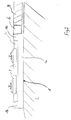
- Fig. 1 shows a first embodiment of a track superstructure solid roadway.
- a hydraulic or bituminous base base layer 1 arranged on the prepared surface 5 .
- this is compressed and frost-resistant gravel material as Frost protection layer installed.
- the base support layer 1 consists of a substantially horizontal section 1a and substantially vertical side sections 1b.
- the side sections 1b form vertically raised areas and extend in the longitudinal direction the solid carriageway on either side of the horizontal section 1a.
- the base base layer 1 which is applied directly to the substrate 5 is trough-shaped.
- a track base layer 2 On the base base layer 1 is a track base layer 2 applied.
- Sleeper blocks 4 are directly embedded in this track support layer 2, i.e. concreted into the filled concrete cross section of the track base layer 2. This Threshold blocks 4 each carry a track.
- the horizontal section 1a and the vertical side sections 1b of the base base layer 1 are made of hydraulically or bituminously bound material, such as for example, hydraulically bound gravel or concrete.
- When using the solid roadway on the open road is next to the vertical side sections 1b crushed stone 7.
- tunnel sections (not shown in Fig. 1) can the area between the side section and scabbard accessible, z. B. with backfill concrete, getting produced.
- Embodiment form the vertical sections 1b of the base base layer 1 a lost formwork for the track base layer 2.
- This can the track support layer 2 are formed in a troubled form and still on one elaborate formwork can be dispensed with.
- the vertical side portions 1b on the horizontal section 1a of the hydraulically bound base base layer be put on.
- the horizontal section 1 a of the base support layer 1 in the side region of projections and / or depressions.
- projections and / or depressions engages a corresponding surface of the vertical side sections on.
- Such projections and / or depressions can already be made during manufacture of the horizontal section are formed.
- it is preferred to form projections and / or depressions in which the grain structure is already one hardened horizontal section of the base base layer made of hydraulic bound material, for example by a water jet on the surface is exposed. This allows a positive and / or non-positive connection formed between the vertical side portions and the horizontal portion become.
- the side sections with the help of a sliding formwork on the already hardened horizontal Section of the base base layer applied.
- the liquefied flows Material in the recesses or encloses the above projections. Thereby becomes a corresponding connection between the vertical side sections and reached the horizontal section.
- the vertical Side sections formed from page elements that correspond to the corresponding Side areas of the vertical section of the base base layer placed become.
- These side elements can also have projections on the contact surface and / or have depressions that correspond to the projections and / or depressions on the vertical portion of the base base layer are trained. These projections or depressions interlock and thus enable a positive connection between the vertical Side sections and the horizontal section of the base base layer 1.
- These projections and / or depressions are preferably in shape a profile toothing formed in the longitudinal direction of the solid carriageway extends. Furthermore, the connection by gluing or the like. improved become.
- separate connecting elements can be provided, which both in the horizontal section of the base base layer 1 and in the Side elements are inserted, so as to form a positive connection to reach.
- the horizontal section 1a of the base base layer 1 and the vertical Side sections 1b made of hydraulically bound material e.g. hydraulic bound gravel
- the base base layer 1 with a horizontal section 1b made of hydraulically bound material (e.g. hydraulically bound gravel) and the vertical side sections 1b made of construction concrete, Einkornbeton or pumice concrete can be produced.
- the trough-shaped base support layer can be covered with a horizontal one Section and vertical side sections of multiple rail tracks record for several parallel lanes. Furthermore, in FIG. 1 Threshold blocks are shown, which each store only one track. alternative the trough-shaped base support layer with a horizontal section and vertical side sections through continuous threshold blocks for common Take up storage of two rail tracks.
- the horizontal section 1a is formed.
- the vertical side sections 1b are on the horizontal section 1a of the hydraulically bound Base base layer 1 formed, the vertical side portions extend in the longitudinal direction of the solid carriageway.
- a track support layer 2 is formed, which extends substantially horizontally and is limited by the vertical side portions 1b.
- the trough-shaped base support layer 1 is produced in one operation and can be produced at the same time using a slipform paver. This applies to both the horizontal section and the vertical section Side portions of the base base layer 1 uses the same material.
- the Base base layer is preferably made of a hydraulic or bituminous bond Material made.
- the two vertical side sections 1b are trained on both sides of the solid carriageway.
- the vertical side sections 1b and the horizontal portion 1a of the base support layer 1 form a trough shape.
- the track support layer 2 is received in the trough shape.
- connection of the vertical side sections and the horizontal Section of the base support layer 1 can be connecting elements (not shown) be introduced.
- the horizontal section 1a and the vertical side section 1b made of hydraulically bound material, in particular hydraulically bound gravel.
- the horizontal Section 1a made of hydraulically bound material, in particular hydraulically bound gravel, be made with the vertical side section 1b is made from structural concrete, single-grain concrete or pumice concrete.
- the trough-shaped Base base layer 1 also produced in a subsequent manufacturing process become.
- the vertical side section 1b becomes horizontal Section 1a of the base base layer 1 placed.
- the horizontal section 1a of the base base layer 1 can be made of concrete be, the vertical side section 1b on the fresh concrete of the horizontal Section 1a of the base base layer 1 is applied. Alternatively the vertical side section 1b on the hardened concrete of the horizontal section 1a of the base base layer 1 are applied.
- projections and / or depressions can already be made during the production of the horizontal section be formed. However, it is preferably projections and / or depressions form in which the grain structure of an already hardened horizontal Section of the base base layer made of hydraulically bound material is exposed, for example, by a water jet on the surface.
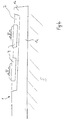
- Fig. 2 shows another embodiment of the track superstructure solid roadway with a trough-shaped base base layer 1.
- This The exemplary embodiment has essentially the same features as that in FIG. 1 shown embodiment, so that only the differences are explained here become. Furthermore, the embodiment shown in Fig. 2 by the The method described above can be produced.
- a cable duct or scrapboard 6 is arranged next to the vertical side section 1b . Still is In addition to the cable duct 6, a layer of asphalt concrete is provided. The hydraulic bound base support layer 1 extends under the cable duct 6 and the layer of asphalt concrete 8.
- the cable duct can be made with a slipform paver or can be used with finished parts. If the track support plate 2 facing Cheek of the cable duct strengthened accordingly and a corresponding distance (Width of the cheek) to the track support plate 2 can be guaranteed by the cable duct be used as the vertical side portion of the base base layer.
- Fig. 3 shows a further embodiment of the track superstructure solid roadway with a trough-shaped base base layer 1.
- This The exemplary embodiment has essentially the same features as that in FIG. 1 and 2 exemplary embodiments shown, so that only the differences are explained here become. Furthermore, the embodiment shown in Fig. 3 can by the methods described above are produced.
- the base base layer 1 according to the exemplary embodiment according to FIG. 3 has one vertical side section 1b, the monolithic (in one operation) is made with the horizontal section 1a as shown on the right 3 is shown.
- On the left side of Fig. 3 is the side boundary by an elevated area of the horizontal portion 1a of the base base layer 1 formed. This raised area is e.g. in the tunnel to that side banquet or, between two adjacent tracks, to the neighboring track educated.
- Fig. 4 shows another embodiment of the track superstructure solid roadway with a trough-shaped base layer 1.
- This embodiment has essentially the same features as that in FIGS. 1 to 3 shown embodiments, so that only the differences are explained here become.
- the embodiment shown in Fig. 4 can by The method described above can be produced.
- the rails are slanted, i.e. with a cant arranged for a curve area. As shown in Fig. 4, the Height of the horizontal section 1a towards the raised area (after on the left in Fig. 4). As a result, the track base layer can be used when cornering 2 are formed at a uniform height.
- Figures 1 to 4 show special embodiments of a track superstructure a solid road.
- the special features of one of the exemplary embodiments can with the special features of the rest of the embodiment be combined.
- the cant shown in Figure 4 of the track due to the special design of the base base layer can be realized in the other exemplary embodiments.
- the in Figure 2 shown cable duct in the raised area shown in Figures 3 and 4 of the horizontal section 1a are embedded or formed.
- the exemplary embodiments show a track superstructure of a fixed carriageway, which has high reliability at low manufacturing costs.
Landscapes
- Engineering & Computer Science (AREA)
- Architecture (AREA)
- Civil Engineering (AREA)
- Structural Engineering (AREA)
- Road Paving Structures (AREA)
Priority Applications (1)
| Application Number | Priority Date | Filing Date | Title |
|---|---|---|---|
| EP01123059A EP1298251A1 (fr) | 2001-09-26 | 2001-09-26 | Superstructure sans ballast pour voies ferrées et procédé pour sa fabrication |
Applications Claiming Priority (1)
| Application Number | Priority Date | Filing Date | Title |
|---|---|---|---|
| EP01123059A EP1298251A1 (fr) | 2001-09-26 | 2001-09-26 | Superstructure sans ballast pour voies ferrées et procédé pour sa fabrication |
Publications (1)
| Publication Number | Publication Date |
|---|---|
| EP1298251A1 true EP1298251A1 (fr) | 2003-04-02 |
Family
ID=8178733
Family Applications (1)
| Application Number | Title | Priority Date | Filing Date |
|---|---|---|---|
| EP01123059A Withdrawn EP1298251A1 (fr) | 2001-09-26 | 2001-09-26 | Superstructure sans ballast pour voies ferrées et procédé pour sa fabrication |
Country Status (1)
| Country | Link |
|---|---|
| EP (1) | EP1298251A1 (fr) |
Cited By (5)
| Publication number | Priority date | Publication date | Assignee | Title |
|---|---|---|---|---|
| WO2004099502A1 (fr) * | 2003-05-07 | 2004-11-18 | Jonathan Middleton | Systeme de rail |
| DE102004061165A1 (de) * | 2004-12-16 | 2006-07-06 | Pfleiderer Infrastrukturtechnik Gmbh & Co. Kg | Betonfahrbahn für Schienenfahrzeuge |
| RU2424391C2 (ru) * | 2008-12-10 | 2011-07-20 | Фердинанд Иренеушевич Стасюлевич | Безбалластный путь на искусственном сооружении |
| RU2424390C2 (ru) * | 2008-12-10 | 2011-07-20 | Фердинанд Иренеушевич Стасюлевич | Безбалластный рельсовый путь на искусственном сооружении |
| CN103147370A (zh) * | 2013-03-29 | 2013-06-12 | 中铁一局集团有限公司 | 一种板式无砟轨道轨道板更换装置及更换方法 |
Citations (4)
| Publication number | Priority date | Publication date | Assignee | Title |
|---|---|---|---|---|
| DE4007710A1 (de) * | 1990-03-10 | 1991-09-12 | Dyckerhoff & Widmann Ag | Verfahren zum herstellen eines eisenbahnoberbaus im tunnel |
| DE29622835U1 (de) * | 1995-01-10 | 1997-06-19 | Grötz, Georg, 76597 Loffenau | Gleisanlage für schienengebundene Fahrzeuge |
| DE19707296A1 (de) * | 1997-02-11 | 1998-08-20 | Hermann Koehne Bauunternehmung | Verfahren zur Herstellung einer festen Fahrbahn und dazu geeigneter Betonfertigteile |
| EP0894898A1 (fr) * | 1997-08-01 | 1999-02-03 | Bahnbau Wels GmbH | Méthode de réalisation d'une voie ferrée et dispositif pour le réglage en hauteur et le support temporaire des rails |
-
2001
- 2001-09-26 EP EP01123059A patent/EP1298251A1/fr not_active Withdrawn
Patent Citations (4)
| Publication number | Priority date | Publication date | Assignee | Title |
|---|---|---|---|---|
| DE4007710A1 (de) * | 1990-03-10 | 1991-09-12 | Dyckerhoff & Widmann Ag | Verfahren zum herstellen eines eisenbahnoberbaus im tunnel |
| DE29622835U1 (de) * | 1995-01-10 | 1997-06-19 | Grötz, Georg, 76597 Loffenau | Gleisanlage für schienengebundene Fahrzeuge |
| DE19707296A1 (de) * | 1997-02-11 | 1998-08-20 | Hermann Koehne Bauunternehmung | Verfahren zur Herstellung einer festen Fahrbahn und dazu geeigneter Betonfertigteile |
| EP0894898A1 (fr) * | 1997-08-01 | 1999-02-03 | Bahnbau Wels GmbH | Méthode de réalisation d'une voie ferrée et dispositif pour le réglage en hauteur et le support temporaire des rails |
Cited By (10)
| Publication number | Priority date | Publication date | Assignee | Title |
|---|---|---|---|---|
| WO2004099502A1 (fr) * | 2003-05-07 | 2004-11-18 | Jonathan Middleton | Systeme de rail |
| GB2417512A (en) * | 2003-05-07 | 2006-03-01 | Jonathan Middleton | Rail system |
| GB2417512B (en) * | 2003-05-07 | 2007-11-21 | Jonathan Middleton | Rail system |
| CN100513687C (zh) * | 2003-05-07 | 2009-07-15 | 乔纳森·米德尔顿 | 铁轨系统 |
| DE102004061165A1 (de) * | 2004-12-16 | 2006-07-06 | Pfleiderer Infrastrukturtechnik Gmbh & Co. Kg | Betonfahrbahn für Schienenfahrzeuge |
| US8146834B2 (en) | 2004-12-16 | 2012-04-03 | Rail.One Gmbh | Concrete carriageway for rail vehicles |
| RU2424391C2 (ru) * | 2008-12-10 | 2011-07-20 | Фердинанд Иренеушевич Стасюлевич | Безбалластный путь на искусственном сооружении |
| RU2424390C2 (ru) * | 2008-12-10 | 2011-07-20 | Фердинанд Иренеушевич Стасюлевич | Безбалластный рельсовый путь на искусственном сооружении |
| CN103147370A (zh) * | 2013-03-29 | 2013-06-12 | 中铁一局集团有限公司 | 一种板式无砟轨道轨道板更换装置及更换方法 |
| CN103147370B (zh) * | 2013-03-29 | 2014-11-26 | 中铁一局集团有限公司 | 一种板式无砟轨道轨道板更换装置及更换方法 |
Similar Documents
| Publication | Publication Date | Title |
|---|---|---|
| DE2306428C3 (de) | Gleisoberbau und Verfahren zu dessen Herstellung | |
| DE3736943C1 (de) | Eisenbahnoberbau,insbesondere fuer sehr hohe Fahrgeschwindigkeiten | |
| DE69924777T2 (de) | Verfahren zum Herstellen eines Gleisoberbaus | |
| DE10138803A1 (de) | Verfahren zum kontinuierlichen Lagern einer Schiene auf einer festen Fahrbahn sowie Justiereinrichtung und feste Fahrbahn | |
| EP0663470B1 (fr) | Procédé d'obtention d'une superstructure de voies ferrées | |
| DE2347636A1 (de) | Verfahren und vorrichtung zur herstellung von fahrbahnen | |
| DE102007046249B4 (de) | Gleiskörper mit geklebten Trögen | |
| DE4236766C2 (de) | Verfahren zum Sanieren eines Dammbaues für eine Fahrbahn | |
| WO2012130425A2 (fr) | Trajectoire de voie de circulation pour véhicules sur rails et support de voie de circulation pour une telle trajectoire de voie de circulation | |
| DE102004061165A1 (de) | Betonfahrbahn für Schienenfahrzeuge | |
| EP1576240B1 (fr) | Procede de construction d'une voie sur dalle et voie de communication ainsi obtenue | |
| EP1048783A1 (fr) | Voie ferrée et sa méthode de réalisation | |
| DE202008005961U1 (de) | Eisenbahnoberbauvorrichtungen | |
| DE10236535B4 (de) | Verfahren zur Herstellung einer Festen Fahrbahn mit der Traversenmethode auf Brücken und anderen Kunstbauwerken | |
| DE10236534B3 (de) | Feste Fahrbahn und Verfahren zu ihrer Herstellung | |
| WO2000061866A1 (fr) | Procede de renouvellement de voies ferrees | |
| DE4423542A1 (de) | Oberbau für Eisenbahn-Gleisanlagen | |
| AT500876B1 (de) | Verfahren zum herstellen einer festen fahrbahn für schienenfahrzeuge | |
| EP1486611B1 (fr) | Procédé de construction d'une voie permanente et une voie permanente | |
| DE102004008357B4 (de) | Schienenfahrbahn | |
| DE69018265T2 (de) | Schiene. | |
| EP2800833B1 (fr) | Voie ferrée sans ballast | |
| WO1995011345A1 (fr) | Superstructure sans ballast a traverses en beton | |
| DE102021127502A1 (de) | Gleis für spurgeführte Schienenfahrzeuge und Verfahren zu dessen Errichtung | |
| DE10227801B3 (de) | Verfahren zur Errichtung eines Gleiskörpers |
Legal Events
| Date | Code | Title | Description |
|---|---|---|---|
| PUAI | Public reference made under article 153(3) epc to a published international application that has entered the european phase |
Free format text: ORIGINAL CODE: 0009012 |
|
| AK | Designated contracting states |
Kind code of ref document: A1 Designated state(s): AT BE CH CY DE DK ES FI FR GB GR IE IT LI LU MC NL PT SE TR Designated state(s): AT BE CH CY DE DK ES FI FR GB GR IE IT LI LU MC NL PT SE TR |
|
| AX | Request for extension of the european patent |
Extension state: AL LT LV MK RO SI |
|
| 17P | Request for examination filed |
Effective date: 20031001 |
|
| AKX | Designation fees paid |
Designated state(s): AT BE CH CY DE DK ES FI FR GB GR IE IT LI LU MC NL PT SE TR |
|
| RAP1 | Party data changed (applicant data changed or rights of an application transferred) |
Owner name: RTE TECHNOLOGIE GMBH |
|
| 17Q | First examination report despatched |
Effective date: 20040922 |
|
| STAA | Information on the status of an ep patent application or granted ep patent |
Free format text: STATUS: THE APPLICATION IS DEEMED TO BE WITHDRAWN |
|
| 18D | Application deemed to be withdrawn |
Effective date: 20050203 |