EP1298652A2 - Lentille d'objective pour une tête de lecture optique - Google Patents
Lentille d'objective pour une tête de lecture optique Download PDFInfo
- Publication number
- EP1298652A2 EP1298652A2 EP02020558A EP02020558A EP1298652A2 EP 1298652 A2 EP1298652 A2 EP 1298652A2 EP 02020558 A EP02020558 A EP 02020558A EP 02020558 A EP02020558 A EP 02020558A EP 1298652 A2 EP1298652 A2 EP 1298652A2
- Authority
- EP
- European Patent Office
- Prior art keywords
- lens
- objective
- optical disk
- aberration
- optical
- Prior art date
- Legal status (The legal status is an assumption and is not a legal conclusion. Google has not performed a legal analysis and makes no representation as to the accuracy of the status listed.)
- Withdrawn
Links
Images


Classifications
-
- G—PHYSICS
- G11—INFORMATION STORAGE
- G11B—INFORMATION STORAGE BASED ON RELATIVE MOVEMENT BETWEEN RECORD CARRIER AND TRANSDUCER
- G11B7/00—Recording or reproducing by optical means, e.g. recording using a thermal beam of optical radiation by modifying optical properties or the physical structure, reproducing using an optical beam at lower power by sensing optical properties; Record carriers therefor
- G11B7/12—Heads, e.g. forming of the optical beam spot or modulation of the optical beam
- G11B7/135—Means for guiding the beam from the source to the record carrier or from the record carrier to the detector
- G11B7/139—Numerical aperture control means
-
- G—PHYSICS
- G11—INFORMATION STORAGE
- G11B—INFORMATION STORAGE BASED ON RELATIVE MOVEMENT BETWEEN RECORD CARRIER AND TRANSDUCER
- G11B7/00—Recording or reproducing by optical means, e.g. recording using a thermal beam of optical radiation by modifying optical properties or the physical structure, reproducing using an optical beam at lower power by sensing optical properties; Record carriers therefor
- G11B7/12—Heads, e.g. forming of the optical beam spot or modulation of the optical beam
- G11B7/135—Means for guiding the beam from the source to the record carrier or from the record carrier to the detector
- G11B7/1372—Lenses
- G11B7/1374—Objective lenses
-
- G—PHYSICS
- G11—INFORMATION STORAGE
- G11B—INFORMATION STORAGE BASED ON RELATIVE MOVEMENT BETWEEN RECORD CARRIER AND TRANSDUCER
- G11B7/00—Recording or reproducing by optical means, e.g. recording using a thermal beam of optical radiation by modifying optical properties or the physical structure, reproducing using an optical beam at lower power by sensing optical properties; Record carriers therefor
- G11B7/12—Heads, e.g. forming of the optical beam spot or modulation of the optical beam
- G11B7/135—Means for guiding the beam from the source to the record carrier or from the record carrier to the detector
- G11B7/1392—Means for controlling the beam wavefront, e.g. for correction of aberration
- G11B7/13922—Means for controlling the beam wavefront, e.g. for correction of aberration passive
Definitions
- the present invention relates to an objective having a high numerical aperture (NA) to realize a large-capacity optical disk, an optical pickup with the objective, an optical disk writer-reader with the objective, and an optical disk reader with the objective.
- NA numerical aperture
- CDs compact disks
- NAs numerical apertures
- DVDs digital versatile disks
- next-generation pickups with objectives that have high NAs and operate on short-wavelength beams.
- the short wavelength beams may include a blue laser beam of about 400 nm in wavelength.
- the paper (A) reports a system employing a single lens having a numerical aperture of 0.7 and the paper (B) a system employing two lens groups having a numerical aperture of 0.85.
- the systems reported in the above papers further thin a CD transmission layer of 1.2 mm and a DVD transmission layer of 0.6 mm.
- the thickness of a transmission layer of an optical disk depends on system margins, it is preferable to be about 0.3 mm or thinner.
- the two-lens-group system reported in the paper (B) realizes a greater numerical aperture than the system of the paper (A).
- the system of the paper (B) needs an assembling process of two lens groups, and therefore, is disadvantageous to mass production and increases costs.
- the two-lens-group system involves a working distance of about 0.13 mm, which is shorter than about 1 mm of a single-lens system in a conventional DVD system.
- the short working distance increases a risk of colliding with an optical disk, thereby deteriorating the reliability of the system.
- Next-generation optical disk systems are required to have single objectives having numerical apertures of 0.7 or above.
- Shotaro Yoshida details a method of designing a double-sided aspherical lens having a high numerical aperture in "Study in Aspherical Aplanatic Lens with Particularly Large Aperture Ratio" in Tohoku University Institute of Scientific Measurements Report, March, 1958.
- Japanese Patent Laid Open Publication 4-163510 discloses a single objective having a numerical aperture of about 0.6 to 0.8.
- a lens having a high numerical aperture can be designed but is not always manufacturable.
- a designed lens must secure a manufacturing tolerance.
- the designed lens must be less affected by wavelength variations or wavelength width of source light, to decrease chromatic aberration.
- a critical manufacturing tolerance for a double-sided aspherical lens for an optical disk is a surface-to-surface eccentricity tolerance.
- the lens In addition to keeping the eccentricity tolerance, the lens must simultaneously satisfy requirements for axial aberration related to perpendicular incident light and off-axis aberration related to oblique incident light.
- off-axis aberration worsens in proportion to an increase in the numerical aperture of the lens even if no consideration is made on the manufacturing tolerance of the lens. If the manufacturing tolerance is considered, the off-axis aberration worsens because the manufacturing tolerance, i.e., the eccentricity tolerance of the lens is securable only by sacrificing the axial aberration and off-axis aberration of the lens.
- the off-axis aberration of the lens greatly worsens when the numerical aperture of the lens is higher than 0.6 and when the eccentricity tolerance is of the micrometer order.
- Chromatic aberration is usually put behind the manufacturing tolerance. Namely, the manufacturing tolerance of a lens is considered at first, and then, the shape of the lens is improved as high as possible to minimize the chromatic aberration of the lens.
- the publication 4-163510 discloses a range of lens shapes to ensure good performance. This disclosure mentions nothing about the securing of eccentricity tolerance.
- a second embodiment of the disclosure explains a lens whose numerical aperture is greater than 0.75 (0.8 for a wavelength of 532 nm). This lens causes a large aberration even on a slight eccentricity. The disclosure mentions nothing about chromatic aberration.
- the disclosures cover a wide range of specifications, and therefore, are insufficient to actually design a good lens.
- the two-lens-group system mentioned above involves a short working distance, and therefore, greatly increases a risk of colliding with an optical disk when the lens groups employ a higher numerical aperture.
- Optical disks are generally made of plastic, which unavoidably involves warp.
- a CD involves a warp of about 0.6 mm and a DVD involves a warp of about 0.3 mm, which is a double improvement from the CD. No further improvement is expected in optical disk warp because the warp depends on disk material.
- the two-lens-group system has a working distance of 0.13 mm as mentioned above. This working distance may differ depending on lens design but must not be increased greater than 0.2 mm, to make a pickup that employs the two-lens-group system compact. With such a short working distance, the lens system will collide with an optical disk if focus servo runs off due to disturbance, vibration, or defects during a disk write or read operation.
- An object of the present invention is to provide an objective (objective lens or lens) for an optical disk, made of a double-sided aspherical single lens (singlet) having a numerical aperture equal to or greater than 0.75 and capable of minimizing axial aberration, off-axis aberration, surface-to-surface eccentricity aberration, and chromatic aberration. Also provided are an optical pickup, an optical disk writer-reader, and an optical disk reader each employing the objective.
- NA numerical aperture
- the highest ray entering the first surface of the lens is parallel to the optical axis.
- the objective of any one of the above aspects has a manufacturable eccentricity tolerance between the first and second surfaces and minimizes off-axis aberration.
- still another aspect of the present invention provides an objective for an optical disk, wherein the objective has first and second aspherical surfaces, a numerical aperture (NA) of the objective is equal to or greater than 0.75 and an angle between a normal to the first surface at a point where a highest ray enters and an optical axis is smaller than a predetermined angle.
- the predetermined angle is, for example, 57 degrees, desirably 56 degrees, more desirably 55 degrees.
- still another aspect of the present invention provides an objective for an optical disk, wherein the objective has first and second aspherical surfaces, numerical aperture (NA) of the objective is equal to or greater than 0.75 and an angle ⁇ between a normal to the first surface at a point where a highest ray enters and an optical axis satisfies the following condition: ⁇ ⁇ ⁇ - 47.3 (0.85 - NA) (degrees) where ⁇ is an angle of 57 degrees, desirably 56 degrees, more desirably 55 degrees.
- NA numerical aperture
- the thickness t along optical axis through center of the objective and focal length f satisfy the following condition: t > (1 + E)f where E is a number equal to or greater than 0, desirably 0.1, more desirably 0.2.
- the objective of any one of the above aspects may have an image magnification of 0.
- the lens desirably focuses parallel rays if the lens involves no manufacturing errors and if a wavelength of source light agrees with a reference wavelength.
- the objective of any one of the above aspects may be designed for source light of 450 nm or shorter in wavelength.
- the objective of any one of the above aspects properly operates on an optical disk having a transmission layer thinner than 0.4 mm, i.e., thinner than a DVD's or CD's transmission layer.
- the focal length f of the objective of any one of the above aspects may be 10 mm or shorter, desirably 3.5 mm or shorter.
- the focal length of the objective of any one of the above aspects is desirably 0 or greater, more desirably 0.2 mm or greater.
- a working distance of the objective depends on the thickness of an optical disk. Desirably, the thinner the optical disk, the larger the working distance. Desirably, if there is a very thin optical disk, a very small lens having a short focal length will sufficiently work on the disk with a very short working distance. Desirably, to work on a front-read optical disk, an objective with a focal length of 0.1 mm may be designed. In this case, a minimum focal length of the objective is desirably defined as f>0. However, there is no means at present to manufacture such a very small lens. Desirably, a practical minimum for the focal length of an objective is f>0.2 mm.
- an upper limit of the thickness t of the objective of any one of the above aspects is determined to make a working distance "dw" of the lens positive.
- an upper limit of lens thickness desirably must be in a range where a finite working distance is securable. Desirably, this range is determined by the focal length and thickness of a lens and the thickness of an optical disk.
- the lens thickness may be in the range of 1.5 mm to 3.5 mm.
- the objective of any one of the above aspects is applicable to an optical pickup.
- the optical pickup employing the objective irradiates a track on an optical disk with a light flux focused by the objective, to write and read information signals to and from the optical disk.
- the optical pickup may have an image magnification of 0.
- Still another aspect of the present invention provides an optical pickup including the objective of any one of the above aspects, a laser source, and a photodetector.
- a working distance of the objective of the optical pickup dependens on the diameter of an optical disk irradiated with a laser beam emitted from the laser source and is defined as follows: (working distance) > 0.005 ⁇ (optical disk radius)
- Still another aspect of the present invention provides an optical disk writer-reader including the optical pickup of the above aspect and a write-read unit to write and read information to and from an optical disk through the pickup.
- the axial aberration, off-axis aberration, and eccentricity tolerance of a lens are secured by balancing the following three conditions:
- the wavelength spread occurs when a semiconductor laser is driven in a multimode by superimposing high frequencies to reduce noise. Suppressing a focusing position change corresponds to securing an axial chromatic aberration.
- a double-sided aspherical lens is capable of simultaneously satisfying the conditions (1) and (2) to secure axial and off-axis aberrations.
- Any lens capable of simultaneously satisfying the conditions (1) and (2) is called an aplanat.
- a lens satisfying the conditions (1) and (2) is generally incapable of satisfying the condition (3) to secure an eccentricity tolerance.
- the lens satisfies the condition (2) and substantially satisfies the condition (3), the lens as a whole satisfies the sine condition and the second surface of the lens substantially satisfies the sine condition.
- the first surface of the lens substantially satisfies the sine condition in connection with a ray height and a refraction angle.
- an aspherical lens that satisfies the conditions (1) and (2) and conforms to the condition (3) has a proper eccentricity tolerance. As mentioned above, it is unable to simultaneously completely satisfy the conditions (1) to (3) because a double-sided aspherical lens has design freedom only in two aspherical surfaces in dealing with the three conditions (1) to (3).
- the higher the numerical aperture of a lens the more the conditions (1) to (3) become unsatisfied by the lens.
- a lens having a high numerical aperture and operating on a short wavelength causes larger aberration because aberration increases in inverse proportion to wavelength.
- Such a lens therefore, has a smaller design margin and must have a strictly controlled shape (paraxial shape).
- lenses according to embodiments of the present invention properly balance and secure the conditions (1) to (3).
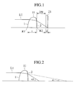
- Figure 1 shows the structure of an objective for an optical disk.
- the objective 11 receives a light flux L1 from a light source (not shown), refracts the light flux L1, and focuses the light flux L1 on a recording plane of the optical disk 21.
- the vertex of a first surface 1 of the lens 11 has a radius of curvature R1, and the vertex of a second surface 2 of the lens 11 has a radius of curvature R2.
- the lens 11 has a thickness t along optical axis through the center of the lens.
- the optical disk 21 has a transmission layer whose thickness is d.
- the lens 11 has a working distance DW.
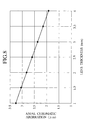
- Figure 2 shows a ray angle in the lens 11 and an image magnification of the second surface 2.
- a highest ray is refracted by the first surface 1 of the lens 11 and forms an angle u1 relative to an optical axis.
- the ray is further refracted by the second surface 2 of the lens 11, to form an angle u2 relative to the optical axis.
- the angle u1 in the formula (6) formed between the highest ray refracted by the first surface 1 and the optical axis is also formed by an aspheric aplanat having a numerical aperture of 0.85 and satisfying the conditions (1) and (2). This angle is determined by the focal length f and thickness t along optical axis through the center of the lens and the optical disk thickness d and is irrelevant to the refractive index of the lens, if the lens has proper characteristics.
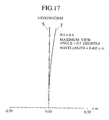
- Figure 3 is a graph showing relationships between lens thickness and angle u1 obtained from a regression formula and design values.
- a black rhombus indicates a design value and a straight line represents the regression formula.
- the design values are calculated based on a focal length f of 2 mm, a lens material refractive index n of 1.75, an optical disk transmission layer thickness d of 0.1 mm, and different lens thicknesses t.
- the design values well agree with the regression formula, to show the correctness of the regression formula.
- Figure 4 is a graph showing relationships between disk thickness and angle u1 obtained from a regression formula and design values.
- a black rhombus indicates a design value and a straight line represents the regression formula.
- the design values are based on a focal length f of 2 mm, a lens material refractive index n of 1.75, a lens thickness t of 3 mm, and different optical disk transmission layer thicknesses d.
- the design values well agree with the regression formula, to show the correctness of the regression formula.
- each of the first and second surfaces of the lens substantially satisfies the sine condition.
- a relationship between the angles u1 and u2 is determined by an image forming operation on the second surface.
- u1 up1 and ⁇ changes according to numerical apertures.
- the lens may be designed to satisfy the condition (3) at the periphery of the lens where an angle of refraction becomes a maximum. This will minimize the eccentricity of the lens. In this way, the paraxial image magnification ⁇ on the second surface depends on numerical apertures.
- the paraxial image magnification ⁇ on the second surface can be generalized by considering numerical apertures.
- Figure 5 is a graph showing relationships between numerical aperture (NA) and image magnification ⁇ ' obtained from a regression formula and design values.
- NA numerical aperture
- ⁇ ' image magnification
- a black rhombus indicates a design value and a straight line represents the regression formula.
- the design values are based on a focal length f of 2 mm, a lens material refractive index n of 1.75, a lens thickness t of 2 mm, and different numerical apertures.
- the design values well agree with the regression formula, to show the correctness of the regression formula.
- Figs. 6A to 6C show the finding of this formula.
- a lens 111 has a refractive index n.
- a first surface 101 of the lens 111 has a radius of curvature R101, and a second surface 102 thereof has an infinite radius of curvature R102.
- a ray L101 entering the lens 111 is in parallel with an optical axis.
- the second surface 102 is flat because the radius of curvature R102 is infinite.
- an image plane (image space) 112 has a refractive index n.
- a ray L101 is in parallel with an optical axis and enters a first surface 101 having a radius of curvature R101.
- the ray L101 intersects the optical axis at a distance L from the vertex of the first surface 101.
- f' L / n
- R101 (n - 1)
- f' (n - 1) / n ⁇ L
- Figure 6C is an expansion to a double convex lens.
- the double convex lens 113 receives a ray having a maximum height h in parallel with an optical axis.
- a lens having a numerical aperture equal to of greater than 0.75 and a sufficient eccentricity tolerance may be designed with the radius R1 of curvature involving a deviation ratio of 0.05, preferably 0.04, more preferably 0.03 or smaller from the value R1 in the above formula.
- Sin(u1) is in inverse proportion to R1. Due to the characteristics of the sin function, a change in sin(u1) is relatively small compared to a change in u1, and therefore, a change in R1 results in a large change in u1. Namely, a tolerance for u1 is greater than a tolerance for R1.
- the influence of the optical disk transmission layer is relatively small if the refractive index of the transmission layer is in the range of 1.45 to 1.65.
- the range of 0.03 to 0.05 for the positive number D is set to cover variations in the refractive index of the optical disk, more precisely, variations in the refractive index of the lens.
- the range for the positive number D may be increased by 5%, to design a proper lens.
- An aspherical lens according to an embodiment of the present invention may be a lens having a rotational symmetry shape around an optical axis (coaxial optical system), or a toric lens having slightly different aspherical shapes in different directions.
- the radius of curvature R1 in each direction of the first surface of the toric lens must be within the above-mentioned range.
- a radius of curvature R2 of the second surface of the lens is automatically determined from a focal length f of the lens as follows:
- R2 G / H
- G f(n - 1)(t(n - 1) / n - R1)
- H (R1 - f(n - 1))
- the radius of curvature R1 at the vertex of the first surface of a lens, and the radius of curvature R2 at the vertex of the second surface of the lens are determined.
- the shapes of the aspherical surfaces of the lens are uniquely determined.
- the lens well satisfies the sine condition of the condition (3), to provide a large eccentricity tolerance.
- an aspherical lens has design freedom only on two aspherical surfaces with respect to the three conditions. Namely, an aspherical lens has a design freedom of 2.
- an eccentricity tolerance it is possible to increase an eccentricity tolerance by slightly changing the aspherical shapes completely satisfying the conditions (1) and (2) as mentioned above. This unavoidably results in deteriorating the axial aberration and off-axis aberration of the lens, but can secure or allow a manufacturing tolerance greater than order of micrometer for example that is important to practically produce the lens.
- the present invention properly deteriorates the axial aberration and off-axis aberration of a lens, thereby balancing the characteristics of the lens and securing an eccentricity tolerance for the lens.
- the present invention properly adjusts the satisfaction levels of the conditions (1) to (3) when designing a lens.
- the conditions (1) to (3) are simultaneously satisfied to some extent by deteriorating the conditions (1) and (2) while securing condition (3). This balancing secures the eccentricity tolerance greater than the order of micrometers for example.
- the spherical radiuses of the lens must meet the conditions (6) and (7). Otherwise, the lens is unable to secure a proper eccentricity tolerance and may involve imbalanced axial aberration and off-axis aberration.
- the thickness t along optical axis through the center of a lens and focal length f of the lens must satisfy the following condition: t > (1 + E)f where E is a number equal to or larger than 0, preferably 0, more preferably 0.1, still more preferably 0.2.
- an aberration increase at the best focus of a lens at each wavelength must be small with respect to a wavelength error.
- the radius of the first surface (incident surface) of the lens becomes larger. More precisely, as the radius of curvature of the first surface of a lens increases, a ray entering the periphery of the lens makes a smaller incident angle ⁇ (an angle between a normal to the first surface and the ray). This results in reducing a refraction effect, which is a nonlinear phenomenon, and reducing spherical aberration with respect to a wavelength change.
- Figure 7 is a graph showing a relationship between lens thickness along optical axis through the center of a lens and residual aberration due to a wavelength error of 5 nm.
- the residual aberration is spherical aberration.
- This graph was prepared on many designed lenses having an NA of 0.85, a focal length of 2.5 mm, and lens material of Ohara LAM70. The lenses were designed with a relatively large eccentricity tolerance.
- an aberration of 0.04 ⁇ or greater occurs when the lens thickness becomes thinner than the focal length.
- the aberration greatly increases when the lens thickness is thinner than 3 mm, which is 1.2 times the focal length.
- an aberration increase caused by wavelength spread of a light source must be small. If there is a light source having wavelength spread, wavelengths around a center wavelength produce focusing errors in addition to the spherical aberration mentioned above when an observation plane is set on a best image plane of the center wavelength. In practice, the influence of the focusing errors is greater than that of spherical aberration. For wavelengths shorter than 450 nm (0.45 ⁇ m), the refractive index of glass greatly disperses to increase the influence of the focusing errors.
- a focusing error occurs due to a change in the back focal length of a lens when a wavelength changes.
- a change in the refractive index n of the lens due to glass dispersion causes a change in the back focal length fb, and this back focal length change is a focusing error.
- Figure 8 is a graph showing a relationship between lens thickness and axial chromatic aberration (or back focal length fb) measured in lenses having a focal length of 2 mm and a refractive index changed from 1.75 to 1.7486.
- a change in the back focal length fb of each lens corresponds to an axial chromatic aberration.
- the refractive index change from 1.75 to 1.7486 corresponds to a refractive index change due to a wavelength change of about 5 nm when glass having an Abbe number of about 45 is used with a wavelength of around 400 nm.
- the lenses are each a plano-convex lens having a radius of curvature R1 of 1.5 mm.
- Lenses according to the present invention are not plano-convex lenses but are double-sided spherical lenses, more precisely, double-sided aspherical lenses.
- Paraxial values including f and fb of a lens are determined by the radius of the vertex of the lens, and therefore, a spherical lens and an aspherical lens make no difference between them.
- a change in the back focal length fb of a spherical lens is substantially free from the influence of bending of the lens, which changes the radiuses of curvature R1 and R2 of the lens while keeping the focal length of the lens, and is substantially equal to that of a plano-convex lens.
- Fig. 8 is effective to consider spherical lenses.
- the axial chromatic aberration becomes smaller in proportion to the lens thickness.
- the lens thickness must be as thick as possible.
- a perfect aplanat has a first surface radius that minimizes an eccentricity aberration increase.
- a radius that realizes a minimum eccentricity aberration is employed as a radius of the vertex of an aspheric shape of a given lens, to balance the axial aberration and off-axis aberration of the lens.
- Balancing these aberration conditions is to consider design freedom levels and is equal to introduce imperfection into a perfect aplanat.
- the radiuses of a lens can be balanced by adding a degree of freedom thereto.
- the angle u1 changes substantially proportionally. Due to the reasons mentioned in connection with a change in the image magnification ⁇ , a change in the angle u1 is not strictly a proportional change. A change in the angle u1 causes a change in the image magnification ⁇ .
- a lens having a numerical aperture including 0.85 forms an angle u1' between a highest ray in the lens and an optical axis, wherein the highest ray enters the first surface of the lens parallel to the optical axis.
- the sine of an angle u1' of the lens must keep a deviation ratio of 0.06, preferably 0.05, more preferably 0.04 from K mentioned above.
- the influence of a transmission layer of an optical disk is relatively small if the refractive index of the transmission layer is in the range of 1.45 to 1.65.
- the range of 0.04 to 0.06 for the positive number D is to cover different disk refractive indexes, more precisely, different lens refractive indexes.
- Lenses having numerical apertures of less than 0.75 have greater margins, and therefore, the range for the positive number D for such lenses may be expanded by 6%.
- the thickness t along optical axis through the center of the lens and focal length f of the lens satisfying the above condition must satisfy the following condition: t > (1 + E) f where E is a number equal to or greater than 0, preferably 0.1, more preferably 0.2.
- a lens that satisfies the condition (4) for an angle u1' between a highest ray in the lens and an optical axis can simultaneously satisfy requirements for axial aberration, off-axis aberration, and an eccentricity tolerance.
- An aspherical lens according to an embodiment of the present invention may be a lens having a rotational symmetry shape around an optical axis (coaxial optical system), or a toric lens having slightly different aspherical shapes in different directions.
- a radius of curvature in each direction of the first surface of the toric lens and the thickness of the toric lens must be within the above-mentioned ranges.
- a working distance of the lens must be greater than a maximum face runout of an optical disk on which the lens works.
- Disk warp angles are specified in disk standards and are 0.6 degrees for CDs and 0.3 degrees for DVDs.
- a maximum face runout of a disk occurs at the periphery thereof. Namely, a CD of 120 mm diameter may have a face runout of 0.6 mm, and a DVD of 120 mm diameter may have a face runout of 0.3 mm.
- the working distance thereof becomes shorter.
- the working distance thereof must be finite. Namely, an upper limit of the thickness of a lens must be in a range where the working distance of the lens is finite. This range is determined by the focal length and thickness of the lens and the thickness of an optical disk.
- the lens thickness may be in the range of 2 mm to 3.5 mm.
- the working distance is 0.3 mm or over. If the maximum disk radius is 25 mm, the working distance is 0.125 mm or over. If the maximum disk radius is 40 mm, the working distance is 0.1 mm or over.
- the focal length of a lens must be increased to allow the large working distance of the lens. Elongating the focal length, however, increases the size of the lens, thereby increasing the size of an optical pickup or an optical disk writer-reader.
- a large lens is disadvantageous for the frequency characteristics of a lens actuator and is unable to realize a high transmission rate.
- the focal length of a lens is preferably 10 mm or smaller, more preferably 3.5 mm or smaller.
- An optical pickup according to an embodiment of the present invention employs the objective of any one of the embodiments of the present invention.
- the optical pickup employing the objective emits a focused light flux toward a track on an optical disk to write and read information signals to and from the optical disk.
- the optical pickup preferably has an image magnification of 0.
- An optical disk writer-reader or an optical disk reader employs the objective of any one of the embodiments of the present invention.
- the optical disk writer-reader or optical disk reader employing the objective emits a focused light flux toward a track on an optical disk to write and read information signals to and from the optical disk.
- the optical disk writer-reader or optical disk reader preferably has an image magnification of 0.
- Z is a distance from the vertex of the surface
- R is a height from an optical axis
- K is a conic constant
- a to F are aspherical coefficients of degrees 4 to 14.
- A is a coefficient for R 4 .
- Figure 9 is a sectional view showing an objective according to the embodiment 1 of the present invention.
- This lens is referred to as the lens 11 01 .
- Table 1 shows specifications of the lens 11 01 .
- Design wavelength 405 nm Numerical aperture 0.85 Focal length 2 mm Entrance pupil diameter 3.4 mm Disk thickness 0.1 mm Image magnification 0
- Table 2 shows design values for the lens 11 01 . Units for radiuses and thicknesses are mm in Table 2 and in other tables that follow.
- Surface No. Surface shape Radius Thickness Refractive Index Conic constant 1 Aspheric 1.71 2.75 1.85 -0.9168291 2 Aspheric -75.9027 0.4605 - 2518.06 3 - Infinite 0.1 1.62230752 - Image surface - - - - - - - -
- Table 3 shows aspherical coefficients for the first surface of the lens 11 01 .
- Coefficient for R 4 0.013687371 Coefficient for R 6 0.00087533585 Coefficient for R 8 0.00087533585 Coefficient for R 10 -0.00077467164 Coefficient for R 12 0.00030433925 Coefficient for R 14 -5.3502493 ⁇ 10 -5
- Table 4 shows aspherical coefficients for the second surface of the lens 11 01 .
- Coefficient for R 4 0.22363727
- Coefficient for R 8 0.72567392
- Coefficient for R 10 -0.47382503 Coefficient for R 12 0.12985027
- a recommended value for R1 is calculated as 1.731695 mm. From this recommended value, the design value for R1 deviates by 1.25%.
- the lens 11 01 is an aplanat that substantially satisfies the conditions (1) and (2) and leaves little error in the condition (3).
- the lens 11 01 involves an axial wavefront aberration of 0.002 ⁇ , which is very small and is substantially zero in practical use.
- the lens shows a wavefront aberration of 0.023 ⁇ for an incident ray of 0.5 degrees in off-axis angle. This value is satisfactory.
- the lens shows a wavefront aberration of 0.036 ⁇ . This aberration concerning the surface-to-surface eccentricity is critical when manufacturing the lens, and the aberration demonstrated by the lens 11 01 is satisfactorily small.
- a working distance of the lens 11 01 is 0.4605 mm, which is larger than a preferable working distance of 0.3 mm for a disk of 60 mm radius.
- a recommended value for sin(u1') calculated from the lens specifications, i.e., K of the formula (8) is 0.4511. From this recommended value, the design value deviates by 1.97%.
- Figure 10 is a graph showing a longitudinal aberration of the lens 11 01
- Fig. 11 is a graph showing an offense against the sine condition of the lens 11 01
- Fig. 12 is a graph showing an astigmatism of the lens 11 01 .
- Figure 13 is a graph showing relationships between R1 (radius of curvature) and wavefront aberration of lenses having the same refractive index and thickness as those of the lens 11 01 and slightly different radiuses of curvature R1.
- the lenses involve an eccentricity of 3 ⁇ m.
- the value A of the formula (7) is 1.767 mm for the lenses having a numerical aperture of 0.75, and 1.732 mm for the lenses having a numerical aperture of 0.85.
- an eccentricity aberration limit is set as 0.04 ⁇
- the radius of curvature R1 of the first surface of a lens must be set within 5% of the recommended value A. Preferably, it must be set within 4% of the recommended value, to secure an eccentricity aberration of 0.04 ⁇ or below.
- an eccentricity of 3 ⁇ m causes an aberration of 0.04 ⁇ .
- Other lens specifications may provide relatively large aberration. Even in such a case, the radius of curvature of a lens must be suppressed within the above-mentioned range.
- the thickness of the lens 11 01 is 1.375 times the focal length thereof.
- the lens 11 01 is made of glass material having a fixed refractive index.
- a wavelength change of 5 nm may change the refractive index to 1.8486, to cause an aberration of 0.01 ⁇ on a best image plane. This aberration is small.
- An axial chromatic aberration is 2.17 ⁇ m, which is also small.
- Figure 14 is a sectional view showing an objective according to the embodiment 2 of the present invention. This lens is referred to as the lens 11 02 .
- Table 5 shows specifications of the lens 11 02 .
- Design wavelength 405 nm Numerical aperture 0.8 Focal length 1.750 mm Entrance pupil diameter 2.8 mm Image magnification 0
- Table 6 shows design values for the lens 11 02 .
- Surface No. Surface shape Radius Thickness Refractive Index Conic constant 1 Aspheric 1.45 2.5 1.75 -0.9753354 2 Aspheric -3.613636 0.395 - - 3 - Infinite 0.1 1.62230752 -188.2991 Image surface - - - - -
- Table 7 shows aspherical coefficients for the first surface of the lens 11 02 .
- Coefficient for R 4 0.023305393 Coefficient for R 6 0.017039056
- Coefficient for R 8 0.0023431785
- Coefficient for R 10 -0.0023798936 Coefficient for R 12 0.0013373117 Coefficient for R 14 -0.00035090993
- Table 8 shows aspherical coefficients for the second surface of the lens 11 02 .
- Coefficient for R 4 0.17601287 Coefficient for R 6 -0.54949768 Coefficient for R 8 0.50420582 Coefficient for R 10 0.12942116 Coefficient for R 12 -0.37309714
- a recommended value for R1, or a value for A of the formula (7) is calculated as 1.4495 mm. From this recommended value, the design value deviates by 0.3%.
- the lens 11 02 is an aplanat that substantially satisfies the conditions (1) and (2) and leaves little error in the condition (3).
- the lens 11 02 involves an axial wavefront aberration of 0.001 ⁇ , which is very small and is substantially zero in practical use.
- the lens shows a wavefront aberration of 0.013 ⁇ for an incident ray of 0.5 degrees in off-axis angle. This value is satisfactory.
- the lens shows a wavefront aberration of 0.023 ⁇ . This aberration concerning the surface-to-surface eccentricity is critical when manufacturing the lens, and the aberration demonstrated by the lens 11 02 is satisfactorily small.
- a working distance of the lens 11 02 is 0.395 mm, which is larger than a preferable working distance of 0.3 mm for a disk of 60 mm radius.
- a recommended value for sin(u1') calculated from the lens specifications, i.e., K of the formula (8) is 0.44. From this recommended value, the design value deviates by 1.7%.
- Figure 15 is a graph showing a longitudinal aberration of the lens 11 02
- Fig. 16 is a graph showing an offense against the sine condition of the lens 11 02
- Fig. 17 is a graph showing an astigmatism of the lens 11 02 .
- the thickness of the lens 11 02 is 1.429 times the focal length thereof.
- the lens 11 02 is made of glass material having a fixed refractive index.
- a wavelength change of 5 nm may change the refractive index to 1.7486, to cause an aberration of 0.01 ⁇ on a best image plane. This aberration is small.
- An axial chromatic aberration is 2.10 ⁇ m, which is also small.
- Figure 18 is a sectional view showing an objective according to the embodiment 3 of the present invention.
- This lens is referred to as the lens 11 03 .
- Table 9 shows specifications of the lens 11 03 .
- Design wavelength 405 nm Numerical aperture 0.85 Focal length 2.2 mm Entrance pupil diameter 3.74 mm Disk thickness 0.1 mm Image magnification 0
- Table 10 shows design values for the lens 11 03 .
- Table 11 shows aspherical coefficients for the first surface of the lens 11 03 .
- Coefficient for R 4 -0.00092006967 Coefficient for R 6 -0.00025706693 Coefficient for R 8 -0.00057872391 Coefficient for R 10 0.0002222827 Coefficient for R 12 -5.6787923 ⁇ 10 -5
- Table 12 shows aspherical coefficients for the second surface of the lens 11 03 . Coefficient for R 4 0.061448774 Coefficient for R 6 -0.13995629 Coefficient for R 8 0.12867014 Coefficient for R 10 -0.043733069
- Table 13 shows refractive indexes of the glass materials. NBF1 1.76775590 Polycarbonate 1.62031432
- a recommended value for R1, or a value for A of the formula (7) is calculated as 1.81581 mm. From this recommended value, the design value deviates by 0.2%.
- the lens 11 03 is approximately an aplanat that substantially satisfies the condition (1), is slightly unsatisfactory for the condition (2) so that the lens 11 03 may suppress eccentricity aberration more than the lens 11 01 , and leaves little error in the condition (3).
- the lens 11 03 involves an axial wavefront aberration of 0.006 ⁇ , which is very small and is substantially zero in practical use.
- the lens shows a wavefront aberration of 0.069 ⁇ for an incident ray of 0.5 degrees in off-axis angle. This value is satisfactory.
- the lens shows a wavefront aberration of 0.034 ⁇ . This aberration concerning the surface-to-surface eccentricity is critical when manufacturing the lens, and the aberration demonstrated by the lens 11 03 is satisfactorily small.
- a recommended value for sin(u1') calculated from the lens specifications, i.e., K of the formula (8) is 0.464. From this recommended value, the design value deviates by 0.43%.
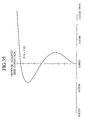
- Figure 19 is a graph showing a longitudinal aberration of the lens 11 03
- Fig. 20 is a graph showing an offense against the sine condition of the lens 11 03
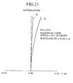
- Fig. 21 is a graph showing an astigmatism of the lens 11 03 .
- the thickness of the lens 11 03 is 1.411 times the focal length thereof.
- a wavelength change of 5 nm to 410 nm may cause an aberration of 0.029 ⁇ on a best image plane. This aberration is small.
- An axial chromatic aberration is 2.21 ⁇ m, which is also small.
- the aspherical shape of the lens may slightly be changed to increase the eccentricity tolerance.
- the axial aberration or the off-axis aberration of the lens may deteriorate.
- an angle (an incident angle) between a normal to the first surface of the lens at the height of a highest ray and an optical axis must conform to a conditional formula. Otherwise, the lens may not secure an eccentricity tolerance and increase axial aberration or off-axis aberration, thereby causing an aberration imbalance. This will be explained in detail.
- the present inventor designed many aplanats that substantially perfectly satisfy the conditions (1) and (2) and meet the condition (3) as high as possible with different focal lengths, lens thicknesses, and glass materials of different refractive indexes. From studies conducted on these lenses, the present inventor found that the incident angle of a highest ray on the first surface of a lens controls axial aberration, off-axis aberration, and eccentricity aberration.
- a preferable design wavelength for a lens is 450 nm or below, more precisely, 405 nm.
- Figure 22 shows the geometries of one of the lenses tested by the present inventor.
- a highest ray L0 is in parallel with an optical axis and enters a first surface 10 of the objective 110. At an incident point on the first surface 10, the ray L0 forms an incident angle ⁇ relative to a normal N.
- the lens 110 has a second surface 20.
- Figures 23A and 23B are graphs showing relationships between incident angle on the first surface 10 and aberration.
- Figure 23A shows off-axis aberration caused by an oblique ray of 0.5 degrees. This off-axis aberration increases as an incident angle on the first surface 10 increases.
- a black rhombus represents a lens made of a glass material having a refractive index of 1.55, a white rhombus a lens made of a glass material having a refractive index of 1.65, a white triangle a lens made of a glass material having a refractive index of 1.75, a white circle a lens made of a glass material having a refractive index of 1.8, and a white square a lens made of a glass material having a refractive index of 1.85.
- Figure 23B shows aberration caused by a surface-to-surface eccentricity of 3 ⁇ m.
- a black square indicates a lens made of a glass material having a refractive index of 1.55, a cross a lens made of a glass material having a refractive index of 1.65, a white triangle a lens made of a glass material having a refractive index of 1.75, a white square a lens made of a glass material having a refractive index of 1.8, and a black rhombus a lens made of a glass material having a refractive index of 1.85.
- Figures 23A and 23B show that aberration increases are substantially linear relative to incident angles on the first surface, although they vary depending on lens design specifications including lens focal lengths, lens thicknesses, and glass material refractive indexes and design techniques including an aspherical coefficient approximation. Axial aberration is properly corrected in each case to 0.006 ⁇ or below.
- Figs. 23A and 23B are general. Namely, the similar aberration characteristics appear for the same incident angle irrespective of glass material refractive indexes, lens thicknesses, or the radiuses of curvature of the vertexes of the first surfaces.
- a lens shape having an aberration of 0.04 ⁇ or below with respect to an eccentricity of 3 ⁇ m and an off-axis aberration of 0.03 ⁇ with respect to an oblique incident light of 0.5 degrees is employed.
- the conditions (1) to (3) are properly adjusted for the lens.
- Adjusting the conditions (1) to (3) is equal to balancing the conditions (1) to (3) by, for example, securing an eccentricity tolerance while slightly sacrificing the axial or off-axis aberration of the lens.
- a lens according to any one of the embodiments of the present invention is an aplanat that substantially satisfies the conditions (1) and (2) to substantially zero the axial aberration and off-axis aberration of the lens and slightly imperfectly satisfy the eccentricity aberration of the lens.
- an incident angle directly relates to the difficulty of processing the metal mold. It is preferable to minimize the incident angle.
- the shape of a metal mold prepared for a lens may slightly differ from the shape of a product lens formed from the metal mold because a high-temperature forming process on the metal mold shrinks the lens. It is convenient, when manufacturing a lens having a numerical aperture of lower than 0.85, to reduce an incident angle accordingly.
- Table 14 shows a relationship between numerical aperture and incident angle found on lenses made according to specifications of the below-mentioned embodiment 4.
- the formula (9) is a regression formula obtained from Table 14.
- Numerical aperture Incident angle (degrees) 0.60 39.8765 0.65 43.0969 0.70 46.2232 0.75 49.1485 0.80 51.6474 0.85 53.2516
- Figure 24 is a graph showing relationships between numerical aperture and incident angle. ⁇ is 53.2516.
- a black rhombus represents an actual design value, and a continuous line represents values calculated from the regression formula.
- Figure 24 also shows data concerning lenses having a lens thickness of 1.5 mm and a glass material refractive index of 1.75 with a black triangle representing design data and a dotted line representing values calculated from the regression formula.
- the regression formula satisfactorily reflects the design values.
- the present inventor prepared design data for many other lenses and obtained similar results. Consequently, it is understood that the regression formula (9) has a sufficient accuracy as a general formula.
- Incident angle conditions for a lens having a numerical aperture below 0.85 will be considered. As the numerical aperture of a lens decreases, an inclination of the periphery of the lens (an incident angle on the first surface of the lens) becomes gentler, to relieve the conditions (1) to (3) and expand a manufacturing tolerance.
- the lens having a numerical aperture below 0.85 shows an aberration increase as an incident angle on the first surface of the lens increases.
- the lens having a numerical aperture below 0.85 may properly be designed by setting an incident angle of 57 degrees, preferably 56 degrees, more preferably 55 degrees or below, like the lens having a numerical aperture of 0.85.
- the lens having a numerical aperture below 0.85 has the advantages mentioned above. Accordingly, design values for the lens having a numerical aperture below 0.85 may be moderated based on the regression formula, to improve the tolerance and performance of the lens.
- the lens having a numerical aperture below 0.85 may properly be formed by setting an incident angle ⁇ on the first surface of the lens as follows: ⁇ ⁇ ⁇ - 47.3 (0.85 - NA) (degrees) where the angle ⁇ is 57 degrees, preferably 56 degrees, more preferably 55 degrees.
- the lenses mentioned above may have a proper eccentricity tolerance but are unsatisfactory in securing chromatic aberration because they give no consideration on the conditions (4) and (5).
- the chromatic aberration will be explained in detail.
- the thickness t along optical axis through the center of a lens and focal length f of a lens must satisfy the following condition: t > (1 + E) f where E is a number equal to or large than 0, preferably 0, more preferably 0.1, still more preferably 0.2.
- an aberration increase at the best focus of a lens must be minimized with respect to an error in each wavelength.
- the radius of the first surface (incident surface) of the lens becomes relatively larger. Namely, as the radius of curvature of the first surface becomes greater, a ray entering the periphery of the lens makes a smaller incident angle ⁇ (an angle between a normal to the first surface and the ray). This results in reducing a refraction effect, which is a nonlinear phenomenon, and reducing spherical aberration with respect to a wavelength error.
- an aberration of 0.04 ⁇ or greater occurs when the thickness of a lens becomes thinner than the focal length of the lens.
- the aberration greatly increases when the lens thickness becomes thinner than 3 mm, which is 1.2 times the focal length.
- Fig. 8 shows that the larger the lens thickness, the better the axial chromatic aberration.
- a lens that satisfies the above-mentioned lens thickness and highest-ray incident angle on the first surface may simultaneously satisfy the conditions (1) to (3) in connection with axial aberration, off-axis aberration, and eccentricity tolerance, as well as the conditions (4) and (5) concerning wavefront aberration and chromatic aberration caused by wavelength errors.
- An aspherical lens according to an embodiment of the present invention may be a lens having a rotational symmetry shape around an optical axis (coaxial optical system), or a toric lens having slightly different aspherical shapes in different directions.
- An incident angle of a highest ray on the toric lens must be within the above-mentioned range.
- Z is a distance from the vertex of the surface
- R is a height from an optical axis
- K is a conic constant
- a to F are aspherical coefficients of degrees 4 to 14.
- A is a coefficient for R 4 .
- Figure 25 is a sectional view showing an objective according to the embodiment 4 of the present invention. This lens is referred to as the lens 11 04 .
- Table 15 shows the specifications of the lens 11 04 .
- Design wavelength 405 nm Numerical aperture 0.85 Focal length 2 mm Entrance pupil diameter 3.4 mm Disk thickness 0.1 mm Image magnification 0
- Table 16 shows design values for the lens 11 04 . Units for radiuses and thicknesses are mm in Table 16 and in other tables that follow.
- Surface No. Surface shape Radius Thickness Refractive Index Conic constant 1 Aspheric 1.71 2.75 1.85 -0.9168291 2 Aspheric -75.9027 0.4605 - 2518.06 3 - Infinite 0.1 1.62230752 - Image surface - - - - - - - -
- Table 17 shows aspherical coefficients for the first surface of the lens 11 04 .
- Coefficient for R 4 0.013687371 Coefficient for R 6 0.00087533585 Coefficient for R 8 0.00087533585 Coefficient for R 10 -0.00077467164 Coefficient for R 12 0.00030433925 Coefficient for R 14 -5.3502493 ⁇ 10 -5
- Table 18 shows aspherical coefficients for the second surface of the lens 11 04 .
- Coefficient for R 4 0.22363727
- Coefficient for R 8 0.72567392
- Coefficient for R 10 -0.47382503 Coefficient for R 12 0.12985027
- the incident angle of a highest ray on the first surface of the lens 11 04 is 53.25 degrees.
- the lens 11 04 is an aplanat that substantially satisfies the conditions (1) and (2) and leaves little error in the condition (3).
- the lens 11 04 involves an axial wavefront aberration of 0.002 ⁇ , which is very small and is substantially zero in practical use.
- the lens shows a wavefront aberration of 0.023 ⁇ for an incident ray of 0.5 degrees in off-axis angle. This value is satisfactory.
- the lens shows a wavefront aberration of 0.036 ⁇ . This aberration concerning the surface-to-surface eccentricity is critical when manufacturing the lens, and the aberration demonstrated by the lens 11 04 is satisfactorily small.
- Figure 26 is a graph showing a longitudinal aberration of the lens 11 04
- Fig. 27 is a graph showing an offense against the sine condition of the lens 11 04
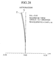
- Fig. 28 is a graph showing an astigmatism of the lens 11 04 .
- the thickness of the lens 11 04 is 1.375 times the focal length thereof.
- the lens 11 04 is made of glass material having a fixed refractive index.
- a wavelength change of 5 nm may change the refractive index to 1.8486, to cause an aberration of 0.01 ⁇ on a best image plane. This aberration is small.
- An axial chromatic aberration is 2.17 ⁇ m, which is also small.
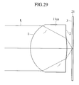
- Figure 29 is a sectional view showing an objective according to the embodiment 5 of the present invention.
- This lens is referred to as the lens 11 05 .
- Table 19 shows specifications of the lens 11 05 .
- Design wavelength 405 nm Numerical aperture 0.8 Focal length 1.750 mm Entrance pupil diameter 2.8 mm Image magnification 0
- Table 20 shows design values for the lens 11 05 .
- Table 21 shows aspherical coefficients for the first surface of the lens 11 05 .
- Coefficient for R 4 0.023305393 Coefficient for R 6 0.017039056
- Coefficient for R 8 0.0023431785
- Coefficient for R 10 -0.0023798936 Coefficient for R 12 0.0013373117 Coefficient for R 14 -0.00035090993
- Table 22 shows aspherical coefficients for the second surface of the lens 11 05 .
- Coefficient for R 4 0.17601287 Coefficient for R 6 -0.54949768 Coefficient for R 8 0.50420582 Coefficient for R 10 0.12942116 Coefficient for R 12 -0.37309714
- the incident angle of a highest ray on the first surface of the lens 11 05 is 51.41 degrees. This angle satisfies the condition (9) that specifies 52.63 degrees for a numerical aperture of 0.8.
- the lens 11 05 is an aplanat that substantially satisfies the conditions (1) and (2) and leaves little error in the condition (3).
- the lens 11 05 involves an axial wavefront aberration of 0.001 ⁇ , which is very small and is substantially zero in practical use.
- the lens 11 05 shows a wavefront aberration of 0.013 ⁇ for an incident ray of 0.5 degrees in off-axis angle. This value is satisfactory. With respect to a surface-to-surface eccentricity of 3 ⁇ m, the lens shows a wavefront aberration of 0.023 ⁇ . This aberration concerning the surface-to-surface eccentricity is critical when manufacturing the lens, and the aberration demonstrated by the lens 11 02 is satisfactorily small.
- Figure 30 is a graph showing a longitudinal aberration of the lens 11 05
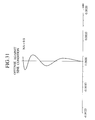
- Fig. 31 is a graph showing an offense against the sine condition of the lens 11 05
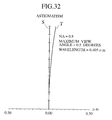
- Fig. 32 is a graph showing an astigmatism of the lens 11 05 .
- the thickness of the lens 11 05 is 1.429 times the focal length thereof.
- the lens 11 05 is made of glass material having a fixed refractive index.
- a wavelength change of 5 nm may change the refractive index to 1.7486, to cause an aberration of 0.01 ⁇ on a best image plane. This aberration is small.
- An axial chromatic aberration is 2.10 ⁇ m, which is also small.
- Figure 33 is a sectional view showing an objective according to the embodiment 6 of the present invention. This lens is referred to as the lens 11 06 .
- Table 23 shows specifications of the lens 11 06 . Design wavelength 405 nm Numerical aperture 0.85 Focal length 2.2 mm Entrance pupil diameter 3.74 mm Disk thickness 0.1 mm Image magnification 0
- Table 24 shows design values for the lens 11 06 .
- Surface No. Surface shape Radius Thickness Glass material Conic constant 1 Aspheric 1.812171 3.104 NBF1 -0.3371789 2 Aspheric -6.507584 0.500289 - -845.6516 3 - Infinite 0.1 Polycarbonate - 4 Image surface - - - - -
- Table 25 shows aspherical coefficients for the first surface of the lens 11 06 .
- Table 26 shows aspherical coefficients for the second surface of the lens 1106. Coefficient for R 4 0.061448774 Coefficient for R 6 -0.13995629 Coefficient for R 8 0.12867014 Coefficient for R 10 -0.043733069
- Table 27 shows refractive indexes of the glass materials. NBF1 1.76775590 Polycarbonate 1.62031432
- the incident angle of a highest ray on the first surface of the lens 11 06 is 55.0 degrees.
- the lens 11 06 is approximately an aplanat that substantially satisfies the condition (1), is slightly unsatisfactory for the condition (2) so that the lens 11 06 may suppress eccentricity aberration more than the lens 11 04 , and leaves little error in the condition (3).
- the lens 11 06 involves an axial wavefront aberration of 0.006 ⁇ , which is very small and is substantially zero in practical use.
- the lens shows a wavefront aberration of 0.069 ⁇ for an incident ray of 0.5 degrees in off-axis angle. This value is satisfactory.
- the lens shows a wavefront aberration of 0.034 ⁇ . This aberration concerning the surface-to-surface eccentricity is critical when manufacturing the lens, and the aberration demonstrated by the lens 11 06 is satisfactorily small.
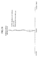
- Figure 34 is a graph showing a longitudinal aberration of the lens 11 06
- Fig. 35 is a graph showing an offense against the sine condition of the lens 11 06
- Fig. 36 is a graph showing an astigmatism of the lens 11 06 .
- the thickness of the lens 11 06 is 1.411 times the focal length thereof.
- a wavelength change of 5 nm to 410 nm may cause an aberration of 0.029 ⁇ on a best image plane. This aberration is small.
- An axial chromatic aberration is 2.21 ⁇ m, which is also small.
- Figure 37 is a sectional view showing an objective according to the embodiment 7 of the present invention.
- This lens is referred to as the lens 11 07 .
- Table 28 shows specifications of the lens 11 07 . Wavelength to use 0.405 ⁇ m Numerical aperture 0.85 Focal length 0.88 mm Entrance pupil diameter 1.496 mm Disk thickness 0.1 mm Image magnification 0
- Table 29 shows design values for the lens 11 07 .
- Table 30 shows aspherical coefficients for the first surface of the lens 11 07 .
- Coefficient for R 4 0.19868545 Coefficient for R 6 -0.0061548457 Coefficient for R 8 0.80023321 Coefficient for R 10 -2.8911336 Coefficient for R 12 5.5467879 Coefficient for R 14 -4.4427687
- Table 31 shows aspherical coefficients for the second surface of the lens 11 07 .
- Coefficient for R 4 1.5351846
- Coefficient for R 6 -14.829258 Coefficient for R 8 33.428793
- Coefficient for R 10 126.25085 Coefficient for R 12 -558.31863
- a recommended value for R1 is calculated as 0.734 mm. From this recommended value, the design value deviates by 0.5%.
- the lens 11 07 is an aplanat that substantially satisfies the conditions (1) and (2) and leaves little error in the condition (3).
- the lens 11 07 involves an axial wavefront aberration of 0.002 ⁇ , which is very small and is substantially zero in practical use.
- the lens shows a wavefront aberration of 0.008 ⁇ for an incident ray of 0.5 degrees in off-axis angle. This value is satisfactory.
- the lens shows a wavefront aberration of 0.037 ⁇ . This aberration concerning the surface-to-surface eccentricity is critical when manufacturing the lens, and the aberration demonstrated by the lens 11 07 is satisfactorily small.
- a recommended value for sin(u1') calculated from the lens specifications, i.e., K of the formula (8) is 0.4367. From this recommended value, the design value deviates by 3.0%.
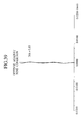
- Figure 38 is a graph showing a longitudinal aberration of the lens 11 07
- Fig. 39 is a graph showing an offense against the sine condition of the lens 11 07
- Fig. 40 is a graph showing an astigmatism of the lens 11 07 .
- a working distance of the lens 11 07 is 0.1735 mm, which is sufficiently larger than a preferable working distance of 0.125 mm for a disk of 25 mm radius.
- FIG 41 shows an optical pickup according to the embodiment 8 of the present invention.
- the optical pickup 30 includes a blue laser diode (LD) 31 serving as a laser source, a beam splitter 32, an objective 33, and a photodetector (PD) and current-voltage converter (I-V) 34.
- LD blue laser diode
- PD photodetector
- I-V current-voltage converter
- the blue LD 31 emits a blue laser beam of, for example, about 405 nm in wavelength.
- the beam splitter 32 separates the beam traveling from the blue LD 32 to an optical disk 35 from a beam traveling from the optical disk 35 to the PD and I-V 34.
- the objective 33 is any one of the lenses of the above embodiments.
- the PD and I-V 34 converts incident light into a current and into a voltage.
- the optical pickup 30 is capable of writing signals (information) to the optical disk 35.
- the blue LD 31 emits a blue beam modulated by a write signal.
- the modulated blue beam is passed through the beam splitter 32 and objective 33 and is focused on the optical disk 35.
- the information is written to a recording plane according to the intensity of the blue beam from the optical pickup 30. For example, the information is recorded as pits or phase changes in lands or grooves on the optical disk 35.
- the optical pickup 30 is also capable of reading a signal from the optical disk 35.
- the blue LD 31 emits a beam of predetermined intensity.
- the beam is passed through the beam splitter 32 and objective 33 and is focused on the recording plane of the optical disk 35, which reflects the beam.
- the reflected beam from the optical disk 35 is passed through the objective 33 and beam splitter 32 and is received by the PD and I-V 34, which converts the received beam into a voltage.
- a signal recorded as a pit in a land or groove on the recording plane of the optical disk 35 is provided as a voltage.
- Figure 42 is a block diagram showing an optical disk writer-reader or an optical disk reader according to the embodiment 9 of the present invention.
- the optical disk writer-reader includes a PRML (partial response maximum likelihood) block 50, a controller block 60, a write compensation block 70, and the optical pickup 30 of Fig. 41.
- PRML partial response maximum likelihood
- controller block 60 the optical disk writer-reader employs a 1-7RLL (run length limit) signal modulation method.
- the PRML block 50 includes an A/D converter 51, a digital equalizer 52, a tap coefficient controller 53, a phase shifter 54, a PLL 55, and a Viterbi decoder 56.
- the controller block 60 includes a 1-7RLL processing unit 61.
- the PRML block 50 receives a signal from the optical pickup 30 through a preamplifier and carries out a PRML signal process on the received signal.
- the controller block 60 receives a signal from the Viterbi decoder 56 of the PRML block 50, and the 1-7RLL processing unit 61 processes the received signal.
- the write compensation block 70 receives a signal from the controller block 60, and according to the received signal, drives the blue LD 31 of the optical pickup 30 through an LD driver.
- the optical disk writer-reader receives a signal read by the optical pickup 30 from the optical disk 35, decodes the received signal, and provides the decoded signal.
- the optical disk writer-reader receives an input signal, encodes and modulates the received signal, and writes the modulated signal to the optical disk 35 through the optical pickup 30.
- the write block of the optical disk writer-reader may be omitted, to provide an optical disk reader.
- the beam splitter mentioned above may be a polarized beam splitter.
- Optical disks applicable to the present invention may have transmission layers of 0.01 mm to 0.3 mm thick.
- the objectives according to the present invention may be made of optical glass such as NBF1 and may have refractive indexes of 1.5 to 2.0.
- the objectives according to the present invention may be formed through optional manufacturing methods, such as a direct forming method to cut or grind a glass material, a glass forming method, a sol-gel glass forming method, and a method to form a resin aspherical layer on a glass or plastic spherical lens material.
- optional manufacturing methods such as a direct forming method to cut or grind a glass material, a glass forming method, a sol-gel glass forming method, and a method to form a resin aspherical layer on a glass or plastic spherical lens material.
- the present invention is capable of providing an objective for an optical disk, made of a single double-sided aspherical lens having a numerical aperture equal to or greater than 0.75 and capable of minimizing axial aberration, off-axis aberration, surface-to-surface eccentricity aberration, and chromatic aberration. Also provided are an optical pickup employing the objective and an optical disk writer-reader and an optical disk reader each employing the optical pickup.
Landscapes
- Physics & Mathematics (AREA)
- Optics & Photonics (AREA)
- Lenses (AREA)
- Optical Head (AREA)
Priority Applications (1)
| Application Number | Priority Date | Filing Date | Title |
|---|---|---|---|
| EP05008622A EP1557830A1 (fr) | 2001-09-21 | 2002-09-17 | Lentille d'objective pour une tête de lecture optique |
Applications Claiming Priority (12)
| Application Number | Priority Date | Filing Date | Title |
|---|---|---|---|
| JP2001290001 | 2001-09-21 | ||
| JP2001290001 | 2001-09-21 | ||
| JP2001289992 | 2001-09-21 | ||
| JP2001289992 | 2001-09-21 | ||
| JP2002118489 | 2002-04-19 | ||
| JP2002118489A JP2003167189A (ja) | 2001-09-21 | 2002-04-19 | 光ディスク用対物レンズ |
| JP2002118318 | 2002-04-19 | ||
| JP2002118318A JP2003167188A (ja) | 2001-09-21 | 2002-04-19 | 光ディスク用対物レンズ |
| JP2002197996 | 2002-07-05 | ||
| JP2002197996A JP2003167192A (ja) | 2001-09-21 | 2002-07-05 | 光ディスク用対物レンズ、光ピックアップ装置、光ディスク記録再生装置及び光ディスク再生装置 |
| JP2002197990A JP2003167191A (ja) | 2001-09-21 | 2002-07-05 | 光ディスク用対物レンズ、光ピックアップ装置、光ディスク記録再生装置及び光ディスク再生装置 |
| JP2002197990 | 2002-07-05 |
Related Child Applications (1)
| Application Number | Title | Priority Date | Filing Date |
|---|---|---|---|
| EP05008622A Division EP1557830A1 (fr) | 2001-09-21 | 2002-09-17 | Lentille d'objective pour une tête de lecture optique |
Publications (2)
| Publication Number | Publication Date |
|---|---|
| EP1298652A2 true EP1298652A2 (fr) | 2003-04-02 |
| EP1298652A3 EP1298652A3 (fr) | 2003-11-19 |
Family
ID=27555001
Family Applications (2)
| Application Number | Title | Priority Date | Filing Date |
|---|---|---|---|
| EP05008622A Withdrawn EP1557830A1 (fr) | 2001-09-21 | 2002-09-17 | Lentille d'objective pour une tête de lecture optique |
| EP02020558A Withdrawn EP1298652A3 (fr) | 2001-09-21 | 2002-09-17 | Lentille d'objective pour une tête de lecture optique |
Family Applications Before (1)
| Application Number | Title | Priority Date | Filing Date |
|---|---|---|---|
| EP05008622A Withdrawn EP1557830A1 (fr) | 2001-09-21 | 2002-09-17 | Lentille d'objective pour une tête de lecture optique |
Country Status (3)
| Country | Link |
|---|---|
| US (1) | US6636366B1 (fr) |
| EP (2) | EP1557830A1 (fr) |
| CN (1) | CN1410794A (fr) |
Cited By (4)
| Publication number | Priority date | Publication date | Assignee | Title |
|---|---|---|---|---|
| WO2004015701A1 (fr) * | 2002-08-05 | 2004-02-19 | Koninklijke Philips Electronics N.V. | Dispositif de lecture comprenant une lentille de focalisait formee de deux materiaux |
| WO2004021065A1 (fr) * | 2002-08-28 | 2004-03-11 | Konica Minolta Holdings, Inc. | Lentille d'objectif pour dispositif de lecture optique, dispositif de lecture optique et dispositif d'enregistrement/de reproduction d'informations optiques |
| WO2004015694A3 (fr) * | 2002-08-05 | 2004-05-21 | Koninkl Philips Electronics Nv | Dispositif de balayage comprenant un systeme d'objectif equipe d'un systeme de protection de la lentille |
| WO2004019323A3 (fr) * | 2002-08-05 | 2004-05-21 | Koninkl Philips Electronics Nv | Lecteur comprenant un systeme d'objectif forme d'un seul materiau |
Families Citing this family (12)
| Publication number | Priority date | Publication date | Assignee | Title |
|---|---|---|---|---|
| US7274646B2 (en) * | 2001-10-04 | 2007-09-25 | Ricoh Company, Ltd. | Object lens for an infinite-type optical pickup, optical pickup and optical information processing device |
| WO2005055214A1 (fr) * | 2003-12-03 | 2005-06-16 | Matsushita Electric Industrial Co., Ltd. | Dispositif a disque optique |
| DE102004028470A1 (de) * | 2004-06-11 | 2005-12-29 | Leica Microsystems (Schweiz) Ag | Augen-, insbesondere Retinaschutzvorrichtung und optisches Element mit einer Freiformfläche für einen Beleuchtungsstrahlengang, sowie Verwendung eines optischen Elements mit Freiformfläche |
| TW200805347A (en) | 2005-11-29 | 2008-01-16 | Konica Minolta Opto Inc | Objective lens for optical pickup apparatus, objective lens unit for optical pickup apparatus and optical pickup apparatus using the same |
| CN101126491B (zh) * | 2006-08-18 | 2011-03-23 | 鸿富锦精密工业(深圳)有限公司 | 发光二极管模组 |
| JP4850032B2 (ja) * | 2006-11-08 | 2012-01-11 | 日立マクセル株式会社 | 光ピックアップレンズ |
| JP2009123317A (ja) * | 2007-11-19 | 2009-06-04 | Fujinon Corp | 対物レンズ、これを備えた光ピックアップ装置、およびこの光ピックアップ装置を搭載した光記録媒体記録および/または再生装置 |
| JP2009123316A (ja) * | 2007-11-19 | 2009-06-04 | Fujinon Corp | 対物レンズ、これを備えた光ピックアップ装置、およびこの光ピックアップ装置を搭載した光記録媒体記録および/または再生装置 |
| JP2009123315A (ja) * | 2007-11-19 | 2009-06-04 | Fujinon Corp | 対物レンズ、これを備えた光ピックアップ装置、およびこの光ピックアップ装置を搭載した光記録媒体記録および/または再生装置 |
| KR20100076784A (ko) * | 2008-12-26 | 2010-07-06 | 삼성전자주식회사 | 비구면 렌즈 및 이를 대물렌즈로 채용한 광픽업 |
| TWI447414B (zh) * | 2012-06-07 | 2014-08-01 | 矽品精密工業股份有限公司 | 測試裝置及測試方法 |
| CN108227052A (zh) * | 2016-12-09 | 2018-06-29 | 深圳超多维科技有限公司 | 一种光学透镜及虚拟现实装置 |
Family Cites Families (6)
| Publication number | Priority date | Publication date | Assignee | Title |
|---|---|---|---|---|
| JP3013404B2 (ja) * | 1990-07-19 | 2000-02-28 | ソニー株式会社 | 高密度記録光ディスク駆動装置用単玉集光レンズ |
| JPH04163510A (ja) | 1990-10-29 | 1992-06-09 | Konica Corp | 光ディスク用対物レンズ |
| JPH05241069A (ja) | 1992-02-28 | 1993-09-21 | Matsushita Electric Ind Co Ltd | 対物レンズとそれを用いた光ヘッド |
| JP3710960B2 (ja) * | 1999-06-22 | 2005-10-26 | シャープ株式会社 | 光ピックアップ装置及び光記録媒体 |
| TW504582B (en) * | 1999-09-01 | 2002-10-01 | Konishiroku Photo Ind | Objective lens for pickup and light pickup apparatus |
| US6590717B2 (en) * | 2000-09-26 | 2003-07-08 | Matsushita Electric Industrial Co., Ltd. | Optical system for optical disk, optical head unit for optical disk, and optical drive device |
-
2002
- 2002-09-06 US US10/235,916 patent/US6636366B1/en not_active Expired - Lifetime
- 2002-09-17 EP EP05008622A patent/EP1557830A1/fr not_active Withdrawn
- 2002-09-17 EP EP02020558A patent/EP1298652A3/fr not_active Withdrawn
- 2002-09-18 CN CN02142703A patent/CN1410794A/zh active Pending
Cited By (5)
| Publication number | Priority date | Publication date | Assignee | Title |
|---|---|---|---|---|
| WO2004015701A1 (fr) * | 2002-08-05 | 2004-02-19 | Koninklijke Philips Electronics N.V. | Dispositif de lecture comprenant une lentille de focalisait formee de deux materiaux |
| WO2004015694A3 (fr) * | 2002-08-05 | 2004-05-21 | Koninkl Philips Electronics Nv | Dispositif de balayage comprenant un systeme d'objectif equipe d'un systeme de protection de la lentille |
| WO2004019323A3 (fr) * | 2002-08-05 | 2004-05-21 | Koninkl Philips Electronics Nv | Lecteur comprenant un systeme d'objectif forme d'un seul materiau |
| WO2004021065A1 (fr) * | 2002-08-28 | 2004-03-11 | Konica Minolta Holdings, Inc. | Lentille d'objectif pour dispositif de lecture optique, dispositif de lecture optique et dispositif d'enregistrement/de reproduction d'informations optiques |
| US7920456B2 (en) | 2002-08-28 | 2011-04-05 | Konica Minolta Holdings, Inc. | Objective lens for optical pickup device, optical pickup device and optical information recording/reproducing apparatus |
Also Published As
| Publication number | Publication date |
|---|---|
| US6636366B1 (en) | 2003-10-21 |
| EP1298652A3 (fr) | 2003-11-19 |
| CN1410794A (zh) | 2003-04-16 |
| EP1557830A1 (fr) | 2005-07-27 |
| US20030184881A1 (en) | 2003-10-02 |
Similar Documents
| Publication | Publication Date | Title |
|---|---|---|
| USRE40329E1 (en) | Single objective lens for use with CD or DVD optical disks | |
| JP3932578B2 (ja) | 対物レンズ及び光学ピックアップ装置 | |
| US6636366B1 (en) | Objective for optical disk, optical pickup, optical disk writer-reader, and optical disk reader | |
| EP1117096B1 (fr) | Tête de lecture optique | |
| US5684641A (en) | Objective lens and optical head apparatus using the objective lens | |
| US6785215B2 (en) | Astigmatic objective lens for optical head | |
| US7301882B2 (en) | Optical pickup device and diffractive optical element | |
| US7233562B2 (en) | Optical pickup device | |
| US6807018B2 (en) | Objective lens for optical pick-up | |
| US7450486B2 (en) | Optical pickup and optical information processing apparatus | |
| US7072254B2 (en) | Optical pickup device and recording medium used therefor | |
| US7301881B2 (en) | Optical pickup device | |
| EP1709635B1 (fr) | Lentille de focalisation | |
| US6775064B2 (en) | Objective lens for optical pick-up | |
| EP1347447A1 (fr) | Tête de lecture optique comportant un élément diffractif pour la compensation d'aberrations | |
| JP2005535063A (ja) | 2種類の材料で形成された対物レンズを含むスキャン装置 | |
| JP2002236252A (ja) | 対物レンズ、カップリングレンズ、集光光学系、光ピックアップ装置及び記録・再生装置 | |
| US20120163155A1 (en) | Optical System for Optical Pickup | |
| RU2379769C2 (ru) | Оптическая система фокусирования света, устройство оптической головки, а также оптическое устройство записи и воспроизведения, в котором используется оптическая система фокусирования света | |
| JPH11353681A (ja) | 光再生装置および光記録媒体 | |
| JP4958022B2 (ja) | 光ピックアップ装置 | |
| JPH10199023A (ja) | 光ピックアップ装置、集光光学系、対物レンズ、再生方法及び光ディスク装置 | |
| JP2004326868A (ja) | 対物光学素子及び光ピックアップ装置 | |
| JP2006252770A (ja) | 光ディスク用対物レンズ | |
| JP2013206496A (ja) | 光ピックアップ装置及び対物レンズ |
Legal Events
| Date | Code | Title | Description |
|---|---|---|---|
| PUAI | Public reference made under article 153(3) epc to a published international application that has entered the european phase |
Free format text: ORIGINAL CODE: 0009012 |
|
| AK | Designated contracting states |
Kind code of ref document: A2 Designated state(s): AT BE BG CH CY CZ DE DK EE ES FI FR GB GR IE IT LI LU MC NL PT SE SK TR Designated state(s): AT BE BG CH CY CZ DE DK EE ES FI FR GB GR IE IT LI LU MC NL PT SE SK TR |
|
| AX | Request for extension of the european patent |
Extension state: AL LT LV MK RO SI |
|
| PUAL | Search report despatched |
Free format text: ORIGINAL CODE: 0009013 |
|
| AK | Designated contracting states |
Kind code of ref document: A3 Designated state(s): AT BE BG CH CY CZ DE DK EE ES FI FR GB GR IE IT LI LU MC NL PT SE SK TR |
|
| AX | Request for extension of the european patent |
Extension state: AL LT LV MK RO SI |
|
| 17P | Request for examination filed |
Effective date: 20031024 |
|
| 17Q | First examination report despatched |
Effective date: 20031229 |
|
| AKX | Designation fees paid |
Designated state(s): DE FR GB |
|
| STAA | Information on the status of an ep patent application or granted ep patent |
Free format text: STATUS: THE APPLICATION IS DEEMED TO BE WITHDRAWN |
|
| 18D | Application deemed to be withdrawn |
Effective date: 20050629 |