EP1299041B1 - Reparatur von zwischenwirbelscheiben - Google Patents
Reparatur von zwischenwirbelscheibenInfo
- Publication number
- EP1299041B1 EP1299041B1 EP00961808A EP00961808A EP1299041B1 EP 1299041 B1 EP1299041 B1 EP 1299041B1 EP 00961808 A EP00961808 A EP 00961808A EP 00961808 A EP00961808 A EP 00961808A EP 1299041 B1 EP1299041 B1 EP 1299041B1
- Authority
- EP
- European Patent Office
- Prior art keywords
- disc
- compression device
- tissue
- toggle
- fastener
- Prior art date
- Legal status (The legal status is an assumption and is not a legal conclusion. Google has not performed a legal analysis and makes no representation as to the accuracy of the status listed.)
- Expired - Lifetime
Links
Images


Classifications
-
- A—HUMAN NECESSITIES
- A61—MEDICAL OR VETERINARY SCIENCE; HYGIENE
- A61B—DIAGNOSIS; SURGERY; IDENTIFICATION
- A61B17/00—Surgical instruments, devices or methods
- A61B17/068—Surgical staplers, e.g. containing multiple staples or clamps
-
- A—HUMAN NECESSITIES
- A61—MEDICAL OR VETERINARY SCIENCE; HYGIENE
- A61B—DIAGNOSIS; SURGERY; IDENTIFICATION
- A61B17/00—Surgical instruments, devices or methods
- A61B17/064—Surgical staples, i.e. penetrating the tissue
-
- A—HUMAN NECESSITIES
- A61—MEDICAL OR VETERINARY SCIENCE; HYGIENE
- A61B—DIAGNOSIS; SURGERY; IDENTIFICATION
- A61B17/00—Surgical instruments, devices or methods
- A61B17/064—Surgical staples, i.e. penetrating the tissue
- A61B17/0644—Surgical staples, i.e. penetrating the tissue penetrating the tissue, deformable to closed position
-
- A—HUMAN NECESSITIES
- A61—MEDICAL OR VETERINARY SCIENCE; HYGIENE
- A61B—DIAGNOSIS; SURGERY; IDENTIFICATION
- A61B17/00—Surgical instruments, devices or methods
- A61B17/56—Surgical instruments or methods for treatment of bones or joints; Devices specially adapted therefor
- A61B17/58—Surgical instruments or methods for treatment of bones or joints; Devices specially adapted therefor for osteosynthesis, e.g. bone plates, screws or setting implements
- A61B17/68—Internal fixation devices, including fasteners and spinal fixators, even if a part thereof projects from the skin
- A61B17/683—Internal fixation devices, including fasteners and spinal fixators, even if a part thereof projects from the skin comprising bone transfixation elements, e.g. bolt with a distal cooperating element such as a nut
-
- A—HUMAN NECESSITIES
- A61—MEDICAL OR VETERINARY SCIENCE; HYGIENE
- A61B—DIAGNOSIS; SURGERY; IDENTIFICATION
- A61B17/00—Surgical instruments, devices or methods
- A61B2017/00004—(bio)absorbable, (bio)resorbable or resorptive
-
- A—HUMAN NECESSITIES
- A61—MEDICAL OR VETERINARY SCIENCE; HYGIENE
- A61B—DIAGNOSIS; SURGERY; IDENTIFICATION
- A61B17/00—Surgical instruments, devices or methods
- A61B2017/00831—Material properties
- A61B2017/00867—Material properties shape memory effect
-
- A—HUMAN NECESSITIES
- A61—MEDICAL OR VETERINARY SCIENCE; HYGIENE
- A61B—DIAGNOSIS; SURGERY; IDENTIFICATION
- A61B17/00—Surgical instruments, devices or methods
- A61B17/064—Surgical staples, i.e. penetrating the tissue
- A61B2017/0646—Surgical staples, i.e. penetrating the tissue for insertion into cartillege, e.g. meniscus
-
- A—HUMAN NECESSITIES
- A61—MEDICAL OR VETERINARY SCIENCE; HYGIENE
- A61B—DIAGNOSIS; SURGERY; IDENTIFICATION
- A61B17/00—Surgical instruments, devices or methods
- A61B17/064—Surgical staples, i.e. penetrating the tissue
- A61B2017/0647—Surgical staples, i.e. penetrating the tissue having one single leg, e.g. tacks
-
- A—HUMAN NECESSITIES
- A61—MEDICAL OR VETERINARY SCIENCE; HYGIENE
- A61B—DIAGNOSIS; SURGERY; IDENTIFICATION
- A61B90/00—Instruments, implements or accessories specially adapted for surgery or diagnosis and not covered by any of the groups A61B1/00 - A61B50/00, e.g. for luxation treatment or for protecting wound edges
- A61B90/06—Measuring instruments not otherwise provided for
- A61B2090/062—Measuring instruments not otherwise provided for penetration depth
-
- A—HUMAN NECESSITIES
- A61—MEDICAL OR VETERINARY SCIENCE; HYGIENE
- A61F—FILTERS IMPLANTABLE INTO BLOOD VESSELS; PROSTHESES; DEVICES PROVIDING PATENCY TO, OR PREVENTING COLLAPSING OF, TUBULAR STRUCTURES OF THE BODY, e.g. STENTS; ORTHOPAEDIC, NURSING OR CONTRACEPTIVE DEVICES; FOMENTATION; TREATMENT OR PROTECTION OF EYES OR EARS; BANDAGES, DRESSINGS OR ABSORBENT PADS; FIRST-AID KITS
- A61F2/00—Filters implantable into blood vessels; Prostheses, i.e. artificial substitutes or replacements for parts of the body; Appliances for connecting them with the body; Devices providing patency to, or preventing collapsing of, tubular structures of the body, e.g. stents
- A61F2/02—Prostheses implantable into the body
- A61F2/30—Joints
- A61F2/44—Joints for the spine, e.g. vertebrae, spinal discs
- A61F2/442—Intervertebral or spinal discs, e.g. resilient
- A61F2002/4435—Support means or repair of the natural disc wall, i.e. annulus, e.g. using plates, membranes or meshes
Definitions
- This invention relates to a toggle compressive device for treating bulging discs, intervertebral instability or spinal stenosis.
- Low-back pain is one of the most prevalent, costly and debilitating ailments afflicting centuries. Seventy to eighty-five percent of all people have back pain at some time in their life. Symptoms are most common among middle-aged adults and are equally common in both men and women. Back pain related to disc disorders, however, is more prevalent among men. The recurrence rate of low back pain ranges from 20% to 44% annually, with lifetime recurrences of 85% (National Institute of Health Guide, Vol. 26, 16 May 1997).
- the disc is comprised of nucleus pulposus and annulus.
- the nucleus pulposus is highly gelatinous with a composition of 70-90% water, 25-60% proteoglycan (dry weight) and 10-20% collagen (dry weight).
- the function of the nucleus pulposus is to sustain prolonged compression during the day and to resiliently re-inflate and reestablish disc height during the night.
- the pulposus is retained and surrounded by layers of cartilaginous annulus. Together the pulposus and the annulus behave as a resilient cushion.
- the weight of the body constantly compresses upon a stack of these cushions alternating between a series of vertebrae.
- the pulposus in each disc also behaves as a water reservoir, which is slowly and constantly being squeezed and drained of its water content through the end plates connected to the vertebrae.
- the disc height decreases throughout the day.
- the weight of the body no longer compresses the disc. Due to the water absorbing nature of the nucleus pulposus, the flow of water is now reversed from the vascular vertebrae back into the proteoglycan and collagen. As a result, the disc height is reestablished, ready to provide support for another day.
- the gelatinous nucleus pulposus exhibits predominantly solid-like behavior with values for dynamic modulus ranging from 7 to 20 kPa (J.C. Iatridis et. al., J. Biomechanics, Vol. 30, No. 10, 1005-1013, 1997).
- the viscoelastic property of the nucleus pulposus undergoes a transition from fluid-like to solid-like behavior (J.C. Iatridis et. al., Journal of Orthopaedic Research, 15:318-322, 1997).
- both the resiliency and disc height diminish.
- Type I Acute back sprain involves damage to ligaments, muscles or even the vertebral end plates from physical overload.
- Type II Organic idiopathic spine pain occurs from increased fluid uptake by the disc.
- Type III Posteriolateral annulus disruption of annular fibers irritates nerves associated with the sacroiliac region, buttock and the back of the thigh. This situation may resolve itself through reabsorption or neutralization by phagocytosis of the disrupted annular fibers.
- Type IV Nerve root irritation by the bulging disc leads to sciatica. This type of disc protrusion is traditionally repaired surgically by tissue removal, chemonucleolysis or percutaneous discectomy.
- Type V Nerve irritation by wandering sequestered disc material has unpredictable exacerbation and remissions.
- Type VI Sequestrum of the annulus and/or nucleus into the spinal canal or intervertebral foramen results in nerve irritation from inflammation, mechanical pressure, chemical irritation, autoimmune response or combinations of irritants.
- Type VII A degenerated disc, with substantial decrease in mechanical properties, is often associated with pain and disability.
- the most common reason for recurrent pain is the bulging or herniation of an intervertebral disc.
- the traditional surgical treatment for a bulging or herniated disc is a series of tissue removing, filling and supporting procedures: (1) laminectomy, removal of lamina from the vertebra which covers part of the herniated disc, (2) discectomy, removal of the disc, (3) bone harvesting usually from the patient's iliac crest, (4) bone cement filling of the donor site, (5) donor bone packing into the vacant disc space, (6) supporting adjacent vertebral bodies with rods, connectors, wire and screws, and finally (7) closing multiple surgical sites.
- Chymopapain is an enzyme used to digest away the nucleus pulposus, the viscous and gel-like substance in the central portion of the disc, which then creates space for the bulging part of the disc to pull back from the encroached nerve root.
- the needle for injecting the chymopapain is accurately guided to the mid-portion of the disc by a stereotaxic device.
- the overall success rate is documented as high as 76%.
- some patients are allergic to the treatment and die from anaphylaxis. Some others suffer from serious neuralgic complications, including paraplegia, paresis, cerebral hemorrhage and transverse myelitis.
- Percutaneous nuclectomy is an alternative method for removing nucleus pulposus without the allergic reaction of chymopapain; and it rarely causes epidural scarring. Similar to chymopapain injection, a needle followed by a tube-like instrument is guided and confirmed by anteroposterior and lateral fluoroscopy. The nucleus pulposus is then removed mechanically or by vacuum. As a result, a void is created within the disc and the bulging decreases, like the air being released from a worn out tire, with the hope that the bulging portion of the disc will recede and no longer encroach upon the adjacent nerve root. This type of procedure is often referred to as a decompression procedure.
- the success of the percutaneous nuclectomy depends on the openness or clarity of the nucleus pulposus channels or outlets leading to the bulge. If the channels are closed, which often is the case, evacuation of the nucleus pulposus from the center of the vertebral disc does not affect the bulge and does not provide any benefit to the patient after the percutaneous nuclectomy procedure.
- Disc space narrowing leads to spinal stenosis, which can be painful when nerves are impinged, entrapped or distorted, by the flattened disc or vertebral bone.
- Depletion of nucleus pulposus from the percutaneous nuclectomy procedure can also cause disc flattening or thinning, leading to vertebral instability and/or spinal stenosis.
- Patent application PCT/US99/21138, WO 00/40159 by Yeung and Yeung, introduces some devices and methods for fastening herniated and/or bulging discs.
- the application covers a resiliently bent fastener, screw, suture, staple and tack, with methods to fasten and hold in the bulging annulus.
- the barbs carve their way into their final holding positions. Unavoidably, the carving damages and weakens the tissue, thereby decreasing the holding strength of the freshly inserted devices.
- tension is applied to the fastened tissue, it is not surprising that the barbs can lose their grip, slip and creep along the carved paths created during insertion, leaving gaps in the supposed closure sites.
- the creeping problem of fastening devices is particularly evident in slow healing tissues, such as menisci, some ligaments and tendons. When gaps are present, the torn tissue does not reattach and heal, even with the passage of time.
- Non-biodegradable fasteners often have the problem of device migration, which can be devastating, especially when the device migrates into nerves, joints or vessels, after numerous cycles of tissue remodeling.
- a compression device for treating a bulging disc, herniated disc, intervertebral instability or spinal stenosis as claimed in the appended claims.
- tissue removal Vastly different from the tissue removing procedures, the methods described in the following two sections use techniques and devices to fasten and restrain the bulging, flattened and/or herniated disc to alleviate irritation of the nerve.
- a compression device For fastening a bulging, herniated or compressed disc, a compression device is used to compress and repair the bulge.
- the compression device is comprised of a rod-like body, a pivotal toggle, a toggle-retaining nut, a toggle deployment device, a disc restrainer and a restrainer nut.
- the compression device is inserted through the defective or dysfunctional disc, using the deployed toggle to distally anchor the compression device.
- the disc restrainer and the restrainer nut are used to compress and hold back the bulging annulus from impinging upon adjacent nerves, for supporting the annular sidewall or for adding disc height by consolidating annular tissue. Any excess length of rod of the compression device is then removed.
- a tissue fastener comprises of a rod-like body with two sets 10 of protruding resilient anchors for clamping tissue together.
- the sets of resilient anchors have opposite clamping directions to counter grip and fasten tissues located at both ends of the tissue fastener.
- the sets of anchors are designed to counter grip or clamp against two tissues, compressing, holding and fastening the tissues together.
- the tissue fastener compresses, maintains and pinches in the bulge of the annulus.
- the resilient anchors are compressed or folded within a fastener deployment tube or needle with a plunger located behind the tissue fastener.
- the deployment tube is inserted through the bulge into the disc, reaching healthy annulus on the other side.
- the bulge is compressed to a non impinging position by a disc compressor. While the compression is held, the fastener deployment tube is withdrawn while the plunger remains stationary.
- the resilient anchors at each end open, counter fastening, restricting and clamping the annular tissues between two ends of the tissue fastener. Since the anchors are deployed or opened within the compressed annulus, the previously bulging annulus is mechanically anchored, fastened and restrained by the tissue fastener, freeing the adjacent nerve from impingement.
- Both the compression device and the fastener are designed to hold, maintain and restrict the bulging annulus. Especially when multiple devices are used, the restrictions fortify the annulus and stabilize the intervertebral disc to minimize pain. Furthermore, the restrictions can also pinch in the annulus, adding disc height and minimizing nerve irritation induced by compressed or flattened discs, a common cause of spinal stenosis.
- the tissue fastener and the delivery devices can also be sized and configured to tissues, such as tendons, ligaments, menisci, organs, skin and/or other structures or devices.
- One embodiment of this invention implants a disc drain tube to drain the nucleus pulposus from the swollen disc into the abdominal cavity.
- the disc drain tube has inlet and outlet openings sized to drain the nucleus pulposus when disc pressure is high.
- a pressure-sensing device coupled with a nucleus pulposus discharge gate can be installed within the drain tube.
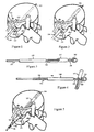
- tissue removal Vastly different from the tissue removing procedures, the methods described in the following two sections use techniques and devices to fasten and restrain the bulging, flattened and/or herniated disc 100 to alleviate irritation of the nerve 102.
- Placement of the compression device 110 begins with a trocar 103 guided through the bulge into the intervertebral disc 100, as depicted in Figure 1.
- a laminotomy removal of a small portion of laminal bone, may be necessary to access the bulge.
- Numerous existing guiding techniques such as anteroposterior and lateral fluoroscopy, MRI, ultrasound or others can be used to guide the trocar 103 into place.
- an angiogram of the blood vessels can be mapped out prior to trocar 103 insertion.
- a dilator 104 is inserted into the bulging disc 100, as shown in Figure 2. The trocar 103 is then removed.
- Figure 3 depicts a compression device 110 with a threaded rod 108 as the body, a nut 105 and a washer 106 to hold a toggle 107, and a deployment tube 109 to activate the toggle 107.
- the unique tubular toggle 107 on the compression device 110 is designed to provide high tensile strength and conform within a small cylindrical space within the dilator 104.
- the toggle 107 has two semi-cylindrical sections centrally connected with openings facing opposite directions. In a delivery position, the concave sides of the opposing semi-cylindrical sections partly cover the rod 108; as depicted in Figure 3, the toggle 107 aligns parallel and fits over the threaded rod 108 of the compression device 110.
- the toggle 107 rotates or opens, forming a T-like configuration with the rod 108 of the compression device 110, as shown in Figure 4.
- the compression device 110 is inserted into the dilator 104 as indicated in Figure 5.
- the toggle 107 is deployed outside the annulus by a gentle push of the sliding toggle deployment tube 109, as indicated in Figure 6, to secure the compression device 110 at the distal end.
- Both the deployment tube 109 and the dilator 104 are withdrawn from the bulging disc 100.
- a disc restrainer 111 and a restrainer nut 112 are installed on the threaded rod 108 as depicted in Figure 7.
- disc gripping elements 148 on the disc restrainer 111 are designed to grasp, hold and/or bundle the weakened annulus together during compression of the bulging disc 100.
- the bulge is compressed by the disc restrainer 111 and the restrainer nut 112, away from the adjacent, previously impinged nerve, as depicted in Figure 8.
- the disc restrainer 111 can be made of a resilient or elastic material, such as nickel-titanium alloy or tempered stainless steel spring, to snugly compress and conform to the contour of a normally shaped annulus with minimal protrusion.
- Excess threaded rod 108 is cut by a pair of endoscopic pliers (not shown); the result is shown in Figure 9.
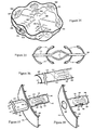
- Figure 10 shows a depression or a recessed pocket in a disc restrainer 111 for concealing the restrainer nut 112 to minimize the possibility of neural impingement by a protruding restrainer nut 112. It is also possible to eliminate the cutting of the threaded rod 108 by substituting the restrainer nut 112 with a bolt 141.
- the bolt 141 passes through a depression or a recessed pocket of the disc restrainer 111 into a tube 155 with inside thread, connected to the toggle 107 assembly. As the bolt 141 advances into the tube 155 and toggle 107 assembly, the disc restrainer 111 is tightened, restricted, compressed and fastened into the annulus.
- the compression and tightening of the bulging disc 100 by the restrainer 111 can collapse and seal channels of the leaking nucleus pulposus 128, thus stopping the herniation.
- FIG. 12 shows a mid-longitudinal view of a flattened bulging disc 100 between two vertebral bodies 159.
- Figure 13 indicates the compression-induced support and thickening of the previously bulging disc 100 by the compression device 110. The compression fortifies and supports the sidewall of the annulus from rolling, thereby minimizing vertebral instability.
- the bulging and flattened disc 100 is being compressed and consolidated, thereby adding cushioning annulus to build height between the two vertebrae 159.
- the main functions of the compression device 110 are to fasten, restrict, tighten, support, fortify, maintain and/or pinch in the annulus of a bulging or flattened disc 100 to alleviate nerve 102 impingement and minimize intervertebral instability and spinal stenosis.
- toggles 107 can also be used to fasten bulging or herniated intervertebral discs 100.
- a two-pieced toggle 107 linked by a hinge 134 connected by a pin is shown in Figure 14.
- Figure 15 depicts a pivotal toggle 107 rotating on another type of pin 133 or screw.
- two disc restrainers 111 can be individually tightened by two bolts 141 to restrict the bulging of an intervertebral disc 100.
- the modified device is called a disc restrictor 156, as shown in Figure 16.
- To install the disc restrictor 156 it is likely that both abdominal and posterior incisions are required, followed by trocar 103 and dilator 104 insertions.
- Figure 17 depicts two disc restrictors 156 fastening, tightening, restricting, supporting and/or pinching in four sections of annulus of a bulging disc 100, adding sidewall support to minimize intervertebral instability and/or building disc height to minimize spinal stenosis in four sections of the bulging and/or flattened disc 100.
- multiple compression devices 110 can also be guided and installed through posterior incisions to minimize back pain and repair dysfunctional intervertebral disc 100.
- the compression device 110 or the disc restrictor 156 is well suited for fastening a lateral bulging annulus without excessively encroaching upon the anterior and posterior longitudinal ligaments and without protruding into the spinal canal.
- the angle of trocar 103 penetration is directed posterior to the common iliac vessels or inferior vena cava. Surgical placement of the compression device 110 can also be done anteriorly through the abdomen to avoid injury to the blood vessels.
- the trocar 103 and the dilator 104 can be made with curvatures.
- the compression device 110 can be made with flexible material.
- Components of the compression device 110 or the disc restrictor 156 can be made with material such as titanium, nickel-titanium, stainless steel or other metals or alloys.
- Some relatively new and biocompatible polymers such as poly-ether-ether-ketone, DELRIN (acetal resin), polysulfone, polycarbonate, polypropylene, polyethylene or others, may have sufficient strength and durability.
- a biodegradable compression device 110 or a portion of the device can be made with poly-lactate, poly-glycolic or other biodegradable polymers. All materials should be able to withstand sterilization by gamma, electron beam, ETO or steam to prevent infection.
- the compression device 110 and the disc restrictor 156 can also be coated or blended with radiopaque, echogenic, growth factor, analgesic, sealing, blood clotting, anti-biotic and/or other materials.
- the compression device 110 and/or the disc restrictor 156 preserves disc material and provides direct, predictable and durable repair of the defective or dysfunctional disc 100 with the potential to stop further leakage of nucleus pulposus.
- Disc fastening also provides the possibilities of minimizing intervertebral instability and increasing disc height to relieve pain and/or discomfort.
- tissue fastener 144 Another intervertebral disc fastening device called a tissue fastener 144 is designed to function while embedded entirely within the repaired disc 119.
- Three major benefits of using the tissue fastener 144 are (1) minimal possibility of rupturing major blood vessels since it does not penetrate through the anterior side of the dysfunctional disc 100, (2) dissection of anterior and posterior longitudinal ligaments is not necessary and (3) no part protrudes to impinge nerve 102, spinal cord or blood vessels.
- Figure 18 depicts a tissue fastener 144 with a rod 114 as body and resilient anchors 113 as tissue clamping elements in their deployed positions.
- the anchors 113 or clamping elements are made with elastic or shape memory material, biased toward the open or deployed positions.
- the anchors 113 with distinct gripping directions, are designed to counter clamp, grip, fasten and hold tissues together, resisting pullout from the tissue.
- the rod 114 joins the anchors 113 and provides the tensile strength required to hold two tissues together.
- the resilient anchors 113 are designed to be elastically or resiliently folded or compressed within a fastener deployment tube 145, as depicted in Figure 19, for delivery into a bulging disc 100.
- the folded spring-like anchors 113 are in delivery positions in the fastener deployment tube 145.
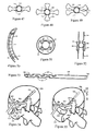
- a trocar 103 is guided through the bulge 100 into the intervertebral disc with anteroposterior and lateral fluoroscopy, MRI, ultrasound or another method. Unlike Figure 1, the trocar is preferred not to penetrate through the intervertebral disc 100, thus avoiding the possibility of puncturing blood vessels. Following the trocar 103, a dilator 104 is inserted into the disc 100 to enlarge the opening.
- the fastener deployment tube 145 loaded with a tissue fastener 144, is inserted into a bulging disc 100, as indicated in Figure 20.
- a disc compressor 118 or tissue manipulative device is used to press the bulge back to a non-nerve-impinging position, as depicted in Figure 21. While the compressor 118 is pressing back the bulge and the plunger 117 is held stationary, the fastener deployment tube 145 is withdrawn to deploy the tissue fastener 144 within the compressed intervertebral disc, as shown in Figure 22. Since the resilient anchors 113 are made of elastic or shape memory material, when the restriction of the fastener deployment tube 145 is lifted, the resilient anchors 113 extend outward to their deployed positions.
- the anchors 113 at the distal end of the tissue fastener 144 grip and fasten onto the healthy annulus.
- the anchors 113 at the proximal end of the fastener 144 open to clamp, grip, fasten and hold the compressed annulus in place.
- the deployed tissue fastener 144 locks and maintains the compressed, previously bulging annulus in a non-nerve-impinging position, forming a repaired disc 119, as shown in Figure 23.
- the compression and fastening of the bulging annulus can, and likely will, collapse and seal the channels of the leaky nucleus pulposus 128 near the bulging annulus, stopping the herniation.
- FIG 24 shows a tissue fastener delivery device 120 with a tissue fastener 144 in the lumen of fastener deployment tube 145 operated by a trigger 122, a stationary plunger 117 held by plunger screws 121 and a built-in disc compressor 118 attached to the device handle 123.
- a trigger lock can be added to prevent the accidental release of the tissue fastener 144 during device 120 insertion.
- Figure 25 shows the deployment of the tissue fastener 144 from the tissue fastener delivery device 120 by using the trigger 122 to withdraw the fastener deployment tube 145.
- the anchors 113 of the tissue fastener 144 extend to their preferred deployed positions. It is also possible to load multiple tissue fasteners 144 within the fastener deployment tube 145 with the capability of deploying one fastener 144 at a time, facilitated by increments in trigger 122 pulling. Multiple fasteners 144 can be used to anchor defective tissue, such as the intervertebral disc or others, in place.
- the distal end of the fastener deployment tube 145 can be sharpened, as indicated in Figure 26, to facilitate the puncturing of the bulging disc 100.
- the deployment tube or needle 145 can also be coated with radiopaque, echogenic, lubricant or other coating material to facilitate device insertion.
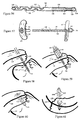
- FIG. 27 depicts a mid-longitudinal view of a screw-like linker 157 protruding from the distal end of the plunger 117 and fastening into an inside threaded link site 158 in the tissue fastener 144.
- the linked assembly located within a tissue fastener deployment needle 145, is then inserted into a bulging disc 100.
- Figure 28 indicates a mid-longitudinal view of deployed distal anchors 113 fastening onto the distal annulus of the bulging disc 100 by partially withdrawing the tissue fastener deployment needle 145, while holding the plunger 117 stationary.
- Figure 29 depicts the pulling of the plunger 117 connected to the tissue fastener 144, pulling in the distal bulging annulus 100.
- Figure 30 shows the compression of the proximal bulging disc 100 by the disc compressor 118, while the plunger 117 is continuously being pulled.
- Figure 31 depicts the full deployment of the tissue fastener 144 by withdrawing the remaining portion of the tissue fastener deployment needle 145 from the bulging disc 100, while continuing to compress the disc 100 and pull the plunger 117.
- Figure 32 shows the fastener 144 tightly fastening the previously bulging disc 100 by counter gripping, clamping, holding, supporting and pulling in the annular wall with the anchors 113.
- tissue fastener 144 and the delivery device 120 are possible.
- a screw from the proximal portion of the tissue fastener 144 can be inserted into a screw hole on the plunger 117.
- a latch or a hinge can couple with an indentation to link between the fastener 144 and the plunger 117, or between the fastener 144 and the tissue deployment needle 145.
- FIG 33 depicts the result of two counter gripping tissue fasteners 144 deployed by the method described in Figures 27 to 32 to support, strengthen, restrict and/or pull in the annular wall of the bulging disc 100.
- Figure 34 shows a previously flattened disc 100 repaired by the combination of two compression devices 110 and a tissue fastener 144 to build disc height in multiple sections of the disc 100 to treat spinal stenosis. At the same time, the flattened annulus is well supported to minimize intervertebral instability. Figure 34 also indicates that the tissue fastener 144 can be well suited for fastening the mid-section of the compressed disc 100 by holding or restricting the anterior and posterior portions of the annular wall with no device protrusion in the central canal.
- the tissue fastener 144 with an elastic spring 132 is particularly well suited for restricting and strengthening the bulging disc 100.
- the distal anchors 113 extend out to make initial penetration into tissue.
- the deployment of the spring 132 follows.
- the spring 132 resiliently spreads apart in the gelatinous nucleus pulposus, pulling in the distal portion of the tissue fastener 144.
- the pulling of the fastener 144 facilitates the deployment of the distal anchors 113, securing the clamping positions within the tissue, before the subsequent deployment of proximal anchors 113.
- the anchors 113 of the tissue fastener 144 can be utilized to fasten a disc restrainer 111.
- Figure 36 depicts anchors 113 of a tissue fastener 144 restricted in an elliptical fastener deployment tube 145 equipped with a plunger 117.
- a disc restrainer 111 having an elliptical opening 149 and a stem 154 with attachment slots 142 is fitted over the elliptical fastener deployment tube 145 along with a disc compressor 118, as shown in Figure 37. Alignment of the attachment slots 142 over the deployed anchors 113 is facilitated by the non-rotary elliptical stem 154 over the elliptical fastener deployment tube 145.
- the assembly is inserted into the bulging disc 100.
- the disc compressor 118 is used to press the disc restrainer 111 against the bulge to a non-nerve-impinging position. While the disc compression continues and the plunger 117 is held stationary behind the tissue fastener 144, the elliptical fastener deployment tube 145 is withdrawn. As the restriction of the deployment tube 145 is removed, the resilient anchors 113 open and fasten into the adjacent attachment slots 142 in the stem 154 of the restrainer 111, as indicated in Figure 38. The anchors 113 at the distal end of the tissue fastener 144 fasten onto healthy annulus, providing the fastening strength for the disc restrainer 111 to compress the bulging tissue.
- FIG 39 depicts a bulging disc 100 repaired by resilient anchors 113 at the distal end and a disc restrainer 111 with a restrainer nut 112 at the proximal end.
- This combination minimizes the possibility of injuring blood vessels anterior to the intervertebral disc and maximizes the restraint of a disintegrating bulging and/or herniated disc 100 posteriorly.
- the tissue fastener 144 and disc restrainer 111 combination can be made with a partially threaded rod 114 fitted within a tissue fastener deployment tube 145.
- a disc restrainer 111 and a restrainer nut 112 are installed. Excess threaded rod 114 is cut; the result is shown in Figure 39.
- the disc restrainer 111 can also be connected to the tissue fastener 144 by anchors 113 as shown in Figures 37 and 38.
- the tissue fastener 144 can also link to the plunger 117 to provide pulling and manipulative capabilities to the fastener 144.
- Figure 40 shows a bulging disc 100 repaired by a compression device 110 at the distal end and tissue fastener 144 at the proximal end of another combination device.
- This combination provides a strong toggle fastening combined with disc repair without protrusions near the nerve or spinal cord.
- the combination is best suited for disc bulges 100 at or near the central canal.
- the concealed anchors 113 fasten and hold the previously bulging annulus 119 with minimal disturbances to the spinal cord and posterior longitudinal ligaments.
- the combination of compression device 110 and tissue fastener 144 can be achieved with a toggle deployment tube 109, which also serves as a tissue fastener deployment tube 145.
- a detachable linkage may be used to connect the fastener 144 to the plunger 117 of a delivery device.
- the procedure for inserting and deploying the toggle 107 is similar to Figures 1, 2, 5 and 6.
- the fastener-linked plunger 117 is pulled to secure the distal end of the combination device.
- a disc compressor 118 is then pressed into the bulging disc 100 and the toggle deployment tube 109 or the fastener deployment tube 145 is withdrawn to deploy the anchors 112. Similar procedures are shown in Figures 21 and 22.
- the linkage is then disconnected; and the result is a normal functioning disc 119, as shown in Figure 40, fastened by the combination devices.
- tissue anchoring by the fastener 144 is the initial tissue penetration. After withdrawing the tissue fastener deployment tube or needle 145, some anchor 113 penetration into the surrounding tissue during the anchor 113 deployment must be initiated. As the anchors 113 are pulled against the tissue, the anchors 113 flare open within the tissue, reaching the maximum anchoring power to firmly hook, clamp, trap and fasten the tissue. Therefore, the tip and/or the outer edge of the anchor 113 should have some tissue penetrating capabilities to initiate entry into the tissue, especially a tough tissue like the annulus.
- the inner edge of the anchor 113 is responsible for fastening, holding, clamping and trapping the tissue; therefore, it should be made as wide and as dull as possible to prevent cutting the tissue, thus maximizing the fastening strength of the tissue fastener 144.
- FIG 41 depicts a pair of wide anchors 113 , which may provide effective anchoring in soft and easily ripped tissue, such as skin, lung, liver or other organs.
- Figure 42 shows a pair of sharp anchors 113, which may be good for anchoring tough, fairly dense and hard to rip tissue, such as bone or the annulus of intervertebral discs.
- the sharp anchors 113 open as a pair of hooks, catching and trapping the anchored tissue at the bases of the sharp anchors 113.
- Figure 43 indicates a pair of combination sharp and wide anchors 113.
- the sharp tips can assist the wide anchors 113 to initiate tissue penetration or a foothold, allowing the full deployment of the wide anchor 113 within the tissue.
- the combination may provide the maximum anchoring power without ripping tissue.
- Additional anchors 113 may improve fastening strength of the tissue fastener 144.
- Figure 44 depicts the anchors 113 rotated between levels, allowing more anchors 113 to be densely stacked within a given length of the tissue fastener 144. As more anchors 113 are available, more layers of tissue will be fastened to further improve the fastening strength within a small space. -
- the composition of the tissue fastener 144 can be formed from modular parts.
- Figure 45 depicts an anchor hole 143 in the rod 114 of a tissue fastener 144.
- Figure 46 indicates a modular anchor 113 inserted into the anchor hole 143.
- the alignment and/or the stacking of the anchors 113 can be customized, specifically for each type of tissue.
- the end view of the fastener 144 in Figure 18 is depicted in Figure 47, with the set of deployed anchors 113 aligned together to fasten onto tissue.
- This type of anchor 113 alignment is good for fastening thin tissue by minimizing the protrusion of the deployed anchors 113.
- Tissue fasteners 144 with anchors 113 aligned together, as indicated in Figure 47, may be ideal for repairing meniscal tears 139, as shown in Figure 61, since the meniscus 135 is a thin cartilage between delicate and sensitive femorotibial joint tissues.
- Figure 48 depicts the end view of deployed anchors 113 similar to the ones in the fastener 144 shown in Figure 44.
- the anchors 113 are stacked over each other at right angles to hold large amounts and the most layers of surrounding tissue.
- This type of anchor 113 alignment indicated in Figures 48 and 44, should provide the most anchoring power, which may be suitable for fastening a tendon 138 to bone.
- Figure 49 depicts the end view of a tissue fastener 114 with the top set of deployed anchors 113 slightly rotated from the set below, to provide some improved anchoring power over the one shown in Figure 47.
- This type of anchor 113 alignment may be useful for fastening bulging discs 100 without excessive protrusion towards the sensitive vertebral end plates, but at the same time occupying and anchoring the maximum amount of annulus to ensure a long lasting disc 100 repair.
- the fastener deployment tube 145 can also be made with a curvature, as shown in Figure 50, to access a hard to reach bulge.
- the rod 114 of the tissue fastener 144 and the plunger 117 should be made flexible or curved.
- the orientation of the tissue fastener 144 may play an important role in the patient's comfort after the device has been implanted. It probably would not be comfortable to have the anchors 113 within the disc, pointing toward the end plates of both vertebral bodies 159 where pain sensation can be felt. To avoid such post-surgical discomfort, the tissue fastener 144 is loaded and oriented so that the anchors 113 are aligned with a visible orientation line 153 drawn on the fastener deployment tube 145, as indicated in Figure 50. Similarly, the tissue fastener 144 can be loaded in a designated orientation with respect to the handle 123 of the delivery device 120.
- the inside lumen 115 or chamber of the fastener deployment tube 145 can be widened or made non-round to prevent or limit fastener 144 rotation within the tube 145, as depicted in a cross-sectional view in Figure 51.
- the surgeon can avoid deploying the anchors 113 toward the direction of sensitive areas.
- penetration markers 116 can be drawn on the fastener deployment tube 145, as shown in Figure 50, and also on the disc compressor 118, as an important verifiable reference point to the surgeon.
- Figure 52 depicts a mid-longitudinal view of a ball joint 152 between two sections of fastener rods 114 to allow rotation and flexibility.
- the ball 150 extends from one section of the rod 114 and is housed in a ball coupling 151 screwed onto or formed in another section of the rod 114.
- the methods used in fastening bulging or herniated discs 100 should also be low in risk and complications.
- the success of percutaneous nuclectomies depends on the condition of the nucleus pulposus channels leading to the bulge. If the channels are closed, which is often the case, evacuation of the nucleus pulposus within the center of the vertebral disc does not affect the bulge and provides no benefit to the patient after the percutaneous nuclectomy procedure.
- the tissue fastener 144 is a direct mechanical device that hooks and locks the bulging annulus back into place. The results should be far more effective, predictable and longer lasting, with no higher risks or complications.
- the tissue fastener 144 can be made with alloy, pure metal, polymer and/or composites.
- nickel-titanium alloy can be used for the anchors 113 and/or the flexible rod 114.
- a stainless steel tempered spring may also provide adequate resiliency, flexibility and elasticity, with sufficient biocompatibility for making the anchors 113 and/or the entire tissue fastener 144.
- Many polymers such as poly-sulfone, poly-ether-ether-ketone, DELRIN (acetal resin), polycarbonate, polyurethane, polypropylene, polyethylene and/or others, may have the physical and biological characteristics required to be a part of the tissue fastener 144.
- tissue fastener 144 can, and mostly likely will, resist device migration with time, after the tissue is adequately reattached or healed, it may be beneficial if a part or the entire tissue fastener 144 is biodegradable.
- Poly-lactate, poly-glycolate, collagen, elastin or other materials may provide the degradation profile to fasten then resorb after the tissue has reattached and healed.
- the tissue fastener 144 can be coated with radiopaque material, echogenic material, growth factor, antibiotic, analgesic, sealant, lubricant, nutrient and/or other substances.
- intervertebral disc 100 fastening include: (1) alleviating nerve 102 impingement, (2) minimizing spinal stenosis and/or (3) stabilizing intervertebral disc 100.
- Annulus compression can be achieved with disc fastening devices, including the compression device 110, disc restrictor 156, tissue fastener 144 and any combinations of these devices.
- Percutaneous nuclectomy is often used to relieve low back pain by evacuating the nucleus pulposus 128 to decompress the intervertebral disc 100. However, when the fluid builds up again in the future, low back pain returns.
- Figure 53 depicts a disc drain tube 124 with nucleus pulposus inlets 125 and an outlet 126.
- the drain tube 124 is inserted into a swollen intervertebral disc 100 through a drain delivery device 136 equipped with a plunger 117, as shown in Figure 54.
- the construction of the drain delivery device 136 can be similar to the tissue fastener delivery device 120 in Figures 24-26. To aid with the insertion, penetration markers and/or curvature on the drain delivery device 136 can be helpful.
- the plunger 117 is held stationary while the drain delivery device 136 is withdrawn to deposit the disc drain tube 124 within the swollen disc 100.
- Figure 55 depicts the uptake of the nucleus pulposus 128 drawn from the channels near the bulge of the disc 100 and the central reservoir through multiple inlets 125, draining through the outlet 126 into the abdomen.
- the bulge 119 reduces in size, away from the previously impinged nerve 127, as shown in Figure 55.
- the drain tube 124 can also be inserted anteriorly through the abdominal cavity to lower the risk of rupturing blood vessels, facilitating proper placement of the outlet 126 and creating only one incision.
- the pressure in the drained intervertebral disc 119 can be regulated or controlled by the diameter of the drain tube 124, number of inlets 125, sizes of the inlets 125 and/or the size of the outlet 126. If the number of inlets 125 is few and diameters of the tube 124, inlets 125 and outlet 126 are small, the disc pressure will remain high. On the other hand, if the inlets 125 are numerous and the diameters of the tube 124, inlets 125 and outlets 126 are large, allowing significant nucleus pulposus 128 drainage to pass, the disc pressure will be low.
- a connector 129 mounting a pressure sensing device 130 coupled with a nucleus pulposus 128 discharge gate 131 can be installed with the disc drain tube 124, as depicted in Figure 56.
- the sensing device 130 triggers the gate 131 to open, allowing the nucleus pulposus 128 to escape out of the outlet 126 slits into the abdominal cavity. It is possible to build a disc drain tube 124 with a variety of pressure regulating designs to regulate and maintain the pressure within the intervertebral disc 119.
- the inlets 125 depicted in Figures 53 and 56 are deep and sunken into the disc drain tube 124 for three major functions: (1) to provide adequate drainage mainly from the central portion of the disc, (2) to minimize the diameter of the tube 124 and (3) to provide tissue ingrowth and/or gripping in the annular portion of the disc, thus preventing tube 124 migration with time. Tissue gripping elements can also be added onto the outer surface of the tube 124 to prevent migration.
- the drain delivery device 136 and the drain tube 124 can also be made curved to avoid blood vessels, bone or nerves to promote proper drainage by tapping into channels of herniating nucleus pulposus 128, using the drain tube 124 as a spigot to release the inflated bulge.
- the disc drain tube 124 can be made biodegradable with poly-lactate, poly-glycolate, collagen, elastin or other degradable materials.
- metallic material such as stainless steel, titanium or nickel-titanium
- metallic material is preferred, especially if the distal end of the disc drain tube 124 is sharpened for disc puncturing capability.
- Numerous long lasting polymers such as poly-ether-ether-ketone, polysulfone, polycarbonate, PTFE, polyurethane, DELRIN (acetal resin), polypropylene, polyethylene or others may meet adequate physical and biocompatible requirements.
- the disc drain tube 124 can be coated with a radiopaque compound, echogenic compound, growth factor, antibiotic, analgesic, sealant, lubricant, nutrient or other substances.
- the disc drain tube 124 provides a continually regulated and/or monitored drainage to prevent further swelling or herniation with a similar low risk level.
- the disc drain tube 124 may provide prolonged or even permanent relief for Types II to VI low back pain.
- the threaded rod 108 is made hollow with nucleus pulposus inlets 125 and an outlet 126, and sealed near the disc restrainer 111 end.
- the mechanical fastening of the compression device 110 provides instant pain relief by alleviating the impinged nerve 102, while the drainage reduces the swelling of the disc.
- tissue fastener deployment tube 145 with at least one tissue fastener 144 is inserted through the tendon 138 into the bone hole 140, as indicated in Figure 58.
- a tissue-manipulating device 146 equipped with tissue manipulating elements 147 is used to position the tendon 138 onto the bone, as shown in Figure 59.
- the tissue fastener deployment tube 145 is withdrawn while the plunger 117 and the tissue-manipulating device 146 are held stationary.
- the distal half of the tissue fastener 144 anchors in the bone hole 140 and the proximal half anchors in the tendon 138, as depicted in Figure 60.
- the tendon 138 can, and most likely will, permanently reattach back onto the bone. Therefore, as mentioned previously, a biodegradable tissue fastener 144 can reattach tissue without the threat of device migration in the distant future or the creation of a stress riser, which weakens the bone.
- the tissue fastener deployment tube 145 can be sharpened as a needle, as shown in Figure 26, to puncture the humerus 137 without drilling.
- penetration markers can be drawn on the outer surface of the tissue fastener deployment tube 145 to assist in the procedure.
- Similar delivery devices like the ones shown in Figures 24 and 26 can be used to puncture and manipulate tissues, then deliver and deploy the tissue fastener 144 with one hand, all through a tiny incision without the nuisance of suture manipulation.
- Both the tissue fastener 144 and the tissue fastener deployment needle 145 can be sized and configured to fasten and repair torn meniscus 135.
- the tissue fastener deployment needle 145 punctures the meniscal body with the guidance of an arthroscope, traversing the tear 139. Penetration markers on the needle 145 can be helpful to determine the depth of needle 145 insertion.
- a tissue manipulating device 146 similar to the one used to position torn tendons 138, as shown in Figure 59, can be utilized to approximate the torn tissue 139 back to the main body of the meniscus 135. To deploy the tissue fastener 144, the plunger 117 is held stationary while the fastener needle 145 is withdrawn from the meniscus 135.
- the anchors 113 resiliently open into deployed positions, gripping, holding, grasping, trapping, hooking and/or fastening tissues at opposing ends of the tissue fastener 144, as indicated in Figure 61.
- the anchors 113 from both ends of the fastener 144 have elastic gripping properties and are designed to resist pullout.
- the torn tissue 139 is elastically fastened and closed by the opposing grips of two sets of resilient anchors 113 of the tissue fastener 144, as shown in Figure 61.
- the fastener deployment needle 145 is effective for both outside-in and inside-out approaches.
- the outside-in approach is to enter from the thick peripheral rim of the meniscus 135 toward the thin tapered portion of the meniscus 135.
- the inside-out approach is to enter from the thin portion toward the thick rim.
- the inside-out approach is more frequently used by surgeons using sutures or meniscal tacks because with tears occurring more often in the posterior portion of meniscus 135; it is less likely to disrupt vessels and nerves.
- the fasteners 144 and deployment needle 145 in this invention can accommodate both approaches.
- tissue deployment needle 145 can deliver the spring-like tissue fastener 144 through a small incision for a quick recovery.
- tissue fastener 144 and the delivery needle 145 are: (1) resilient tissue fastening, (2) minimal fastener migration, (3) minimally invasive, (4) accessible to deep body targets, (5) suture-free fastening, (6) attachable to bone, (7) minimal surgical space, (8) permanent or degradable fastening, (9) simple to use and (10) capable of manipulating tissue.
Landscapes
- Health & Medical Sciences (AREA)
- Life Sciences & Earth Sciences (AREA)
- Surgery (AREA)
- Molecular Biology (AREA)
- Engineering & Computer Science (AREA)
- Biomedical Technology (AREA)
- Heart & Thoracic Surgery (AREA)
- Medical Informatics (AREA)
- Nuclear Medicine, Radiotherapy & Molecular Imaging (AREA)
- Animal Behavior & Ethology (AREA)
- General Health & Medical Sciences (AREA)
- Public Health (AREA)
- Veterinary Medicine (AREA)
- Prostheses (AREA)
- Coating By Spraying Or Casting (AREA)
- Surgical Instruments (AREA)
Claims (17)
- Eine Druckvorrichtung (110) zur Behandlung einer gewölbten Scheibe, eines Bandscheibenvorfalls, einer intervertebraler Instabilität oder einer spinalen Stenosis, wobei die Druckvorrichtung umfaßt;eine Stange (108) mit einem ersten Ende und einem zweiten Ende, einen Gelenkhebel (107), der drehbar mit dem ersten Ende der Stange verbunden ist, wobei der Gelenkhebel eine Zuführungsposition und eine eingesetzte Position aufweist,
dadurch gekennzeichnet, daß die Druckvorrichtung desweiteren umfaßt eine Gelenkhebeleinsatzröhre (109)
und ein Element (111) zum Zurückhalten einer Scheibe, das an dem zweiten Ende der Stange (108) befestigbar ist. - Druckvorrichtung nach Anspruch 1, wobei, wenn der Gelenkhebel in der eingesetzten Position ist, der Gelenkhebel hauptsächlich senkrecht zu der Stange ausgerichtet ist, und wenn der Gelenkhebel in der Zuführungsposition ist, ist der Gelenkhebel hauptsächlich parallel zu der Stange ausgerichtet.
- Druckvorrichtung nach Anspruch 1, wobei der Gelenkhebel umfaßt:einen ersten hauptsächlich halb-zylindrischen Teil,und einen zweiten hauptsächlich halb-zylindrischen Teil,wobei, in der eingesetzten Position, eine erste konkave Fläche des ersten hauptsächlich halb-zylindrischen Teils hauptsächlich in Richtung eines proximalen Endes der Stange gerichtet ist, und eine zweite konkave Fläche des zweiten hauptsächlich halb-zylindrischen Teils ist hauptsächlich in Richtung eines distalen Endes der Stange gerichtet,
und wobei, in der Zuführungsposition, die erste konkave Fläche und die zweite konkave Fläche teilweise die Stange umschließen. - Druckvorrichtung nach Anspruch 1, desweiteren umfassend eine Mutter, die an dem ersten Ende der Stange befestigt ist, und wobei vorzugsweise die Mutter größer als die Öffnung ist, die sich durch den Gelenkhebel erstreckt.
- Druckvorrichtung nach Anspruch 1, wobei der Gelenkhebel mit dem ersten Ende der Stange durch einen Stift verbunden ist.
- Druckvorrichtung nach Anspruch 5, wobei der Gelenkhebel ein erstes Element, das einen ersten Abschnitt bildet, und ein zweites Element aufweist, das einen zweiten Abschnitt des Gelenkhebels bildet, und wobei vorzugsweise das erste Element und das zweite Element sich unabhängig voneinander bewegen.
- Druckvorrichtung nach Anspruch 5, wobei der Stift den Gelenkhebel mit der Stange an einem mittleren Abschnitt des Gelenkhebels verbindet.
- Druckvorrichtung nach Anspruch 1, wobei das Element zum Zurückhalten einer Scheibe eine Vielzahl von sich hiervon erstreckenden Gewebehalteelementen aufweist.
- Druckvorrichtung nach Anspruch 1, wobei das Element zum Zurückhalten einer Scheibe elastisch ist.
- Druckvorrichtung nach Anspruch 1, wobei die Stange mit einem Gewinde versehen ist.
- Vorrichtung nach Anspruch 10, desweiteren umfassend eine Mutter, die das Element zum Zurückhalten einer Scheibe hält, und wobei vorzugsweise das Element zum Zurückhalten einer Scheibe eine Vertiefung aufweist und die Mutter zumindest teilweise in die Vertiefung vertieft ist.
- Druckvorrichtung nach Anspruch 10, wobei das Element zum Zurückhalten einer Scheibe um ein mit einem Gewinde versehenes rohrförmiges Element angeordnet ist, das ausgebildet und ausgelegt ist, um der Stange zu entsprechen, und wobei vorzugsweise das rohrförmige Element einen mit einem Innengewinde versehenen Hohlraum aufweist und der Hohlraum ausgelegt und ausgebildet ist, um mit der Stange in Eingriff zu treten.
- Druckvorrichtung nach Anspruch 10, wobei die Stange einen mit einem Innengewinde versehenen Hohlraum aufweist, der sich hierin erstreckt, und wobei das Element zum Zurückhalten einer Scheibe um einen mit einem Außengewinde versehenen Bolzen angeordnet ist, wobei der Bolzen ausgelegt und ausgebildet ist, um mit dem Hohlraum in Eingriff zu treten.
- Druckvorrichtung nach Anspruch 1, wobei mindestens ein Abschnitt der Druckvorrichtung aus einem Material gebildet ist, das aus der Gruppe von Materialien bestehend aus Titan, Nickeltitan, Edelstahl,
Polyetheretherketon, Acetalharz, Polysulfon, Polycarbonat, Polypropylen, Polyethylen, Polylactatpolymer und Polyglycolpolymer ausgewählt ist. - Druckvorrichtung nach Anspruch 1, wobei die Druckvorrichtung mit einer Schicht beschichtet ist, die aus der Gruppe von Beschichtungen bestehend aus röntgenstrahlundurchlässigem Material, echoerzeugendem Material, Zunahme, analgetischem Material, Dichtungsmaterial, Blutgerinnungsmaterial und antibiotischem Material ausgewählt ist.
- Druckvorrichtung nach Anspruch 1, wobei die Druckvorrichtung flexibel ist.
- Druckvorrichtung nach Anspruch 1, wobei die Druckvorrichtung ausgelegt und ausgebildet ist, um eine disfunktionelle Zwischenwirbelscheibe zu behandeln.
Applications Claiming Priority (3)
| Application Number | Priority Date | Filing Date | Title |
|---|---|---|---|
| US21112500P | 2000-06-12 | 2000-06-12 | |
| US211125P | 2000-06-12 | ||
| PCT/US2000/024921 WO2001095818A1 (en) | 2000-06-12 | 2000-09-12 | Intervertebral disc repair |
Publications (2)
| Publication Number | Publication Date |
|---|---|
| EP1299041A1 EP1299041A1 (de) | 2003-04-09 |
| EP1299041B1 true EP1299041B1 (de) | 2006-10-04 |
Family
ID=22785673
Family Applications (1)
| Application Number | Title | Priority Date | Filing Date |
|---|---|---|---|
| EP00961808A Expired - Lifetime EP1299041B1 (de) | 2000-06-12 | 2000-09-12 | Reparatur von zwischenwirbelscheiben |
Country Status (5)
| Country | Link |
|---|---|
| EP (1) | EP1299041B1 (de) |
| AT (1) | ATE341280T1 (de) |
| AU (1) | AU2000273709A1 (de) |
| DE (1) | DE60031175D1 (de) |
| WO (1) | WO2001095818A1 (de) |
Families Citing this family (49)
| Publication number | Priority date | Publication date | Assignee | Title |
|---|---|---|---|---|
| US6592625B2 (en) | 1999-10-20 | 2003-07-15 | Anulex Technologies, Inc. | Spinal disc annulus reconstruction method and spinal disc annulus stent |
| US7615076B2 (en) | 1999-10-20 | 2009-11-10 | Anulex Technologies, Inc. | Method and apparatus for the treatment of the intervertebral disc annulus |
| US8632590B2 (en) | 1999-10-20 | 2014-01-21 | Anulex Technologies, Inc. | Apparatus and methods for the treatment of the intervertebral disc |
| US7052516B2 (en) | 1999-10-20 | 2006-05-30 | Anulex Technologies, Inc. | Spinal disc annulus reconstruction method and deformable spinal disc annulus stent |
| US20030153976A1 (en) | 1999-10-20 | 2003-08-14 | Cauthen Joseph C. | Spinal disc annulus reconstruction method and spinal disc annulus stent |
| US7004970B2 (en) | 1999-10-20 | 2006-02-28 | Anulex Technologies, Inc. | Methods and devices for spinal disc annulus reconstruction and repair |
| EP1399077B1 (de) | 2001-02-13 | 2006-08-23 | Jeffrey E. Yeung | Kompressionsvorrichtung und Trokar zum Reparieren einer Zwischenwirbelprothese |
| US8002775B2 (en) | 2001-10-24 | 2011-08-23 | Warsaw Orthopedic, Inc. | Methods and instruments for treating pseudoarthrosis |
| WO2003057054A2 (en) * | 2001-12-27 | 2003-07-17 | Osteotech Inc. | Bone fasteners and method for stabilizing vertebral bone facets using the bone fasteners |
| US20040044364A1 (en) * | 2002-08-29 | 2004-03-04 | Devries Robert | Tissue fasteners and related deployment systems and methods |
| US7083630B2 (en) | 2002-08-29 | 2006-08-01 | Scimed Life Systems, Inc. | Devices and methods for fastening tissue layers |
| AU2012261709B2 (en) * | 2002-12-24 | 2015-08-27 | Krt Investors, Inc. | Spinal disc annulus reconstruction method and spinal disc annulus stent |
| DE102004027461A1 (de) * | 2004-06-04 | 2005-12-22 | Bip Gmbh | Marker und Vorrichtung zum Einbringen eines Markers in menschliches oder tierisches Gewebe |
| EP1824403A1 (de) * | 2004-12-16 | 2007-08-29 | Horst Döllinger | Implantat zur behandlung der lumbalen spinalkanalstenose |
| US7361196B2 (en) | 2005-02-22 | 2008-04-22 | Stryker Spine | Apparatus and method for dynamic vertebral stabilization |
| US8795364B2 (en) | 2005-05-06 | 2014-08-05 | Kensey Nash Corporation | System and devices for the repair of a vertebral disc defect |
| US9549739B2 (en) | 2005-05-20 | 2017-01-24 | Neotract, Inc. | Devices, systems and methods for treating benign prostatic hyperplasia and other conditions |
| US8668705B2 (en) | 2005-05-20 | 2014-03-11 | Neotract, Inc. | Latching anchor device |
| US10925587B2 (en) | 2005-05-20 | 2021-02-23 | Neotract, Inc. | Anchor delivery system |
| US8603106B2 (en) | 2005-05-20 | 2013-12-10 | Neotract, Inc. | Integrated handle assembly for anchor delivery system |
| US8425535B2 (en) | 2005-05-20 | 2013-04-23 | Neotract, Inc. | Multi-actuating trigger anchor delivery system |
| US7645286B2 (en) | 2005-05-20 | 2010-01-12 | Neotract, Inc. | Devices, systems and methods for retracting, lifting, compressing, supporting or repositioning tissues or anatomical structures |
| US7758594B2 (en) | 2005-05-20 | 2010-07-20 | Neotract, Inc. | Devices, systems and methods for treating benign prostatic hyperplasia and other conditions |
| US8945152B2 (en) | 2005-05-20 | 2015-02-03 | Neotract, Inc. | Multi-actuating trigger anchor delivery system |
| US10195014B2 (en) | 2005-05-20 | 2019-02-05 | Neotract, Inc. | Devices, systems and methods for treating benign prostatic hyperplasia and other conditions |
| US8628542B2 (en) | 2005-05-20 | 2014-01-14 | Neotract, Inc. | Median lobe destruction apparatus and method |
| US9504461B2 (en) | 2005-05-20 | 2016-11-29 | Neotract, Inc. | Anchor delivery system |
| US7824414B2 (en) | 2005-07-22 | 2010-11-02 | Kensey Nash Corporation | System and devices for the repair of a vertebral disc defect |
| US8109973B2 (en) | 2005-10-31 | 2012-02-07 | Stryker Spine | Method for dynamic vertebral stabilization |
| US8163019B2 (en) | 2006-12-22 | 2012-04-24 | Pioneer Surgical Technology, Inc. | Implant restraint device and methods |
| US8163022B2 (en) | 2008-10-14 | 2012-04-24 | Anulex Technologies, Inc. | Method and apparatus for the treatment of the intervertebral disc annulus |
| US8808336B2 (en) | 2009-07-14 | 2014-08-19 | Neil Duggal | Joint arthrodesis and arthroplasty |
| US8460319B2 (en) | 2010-01-11 | 2013-06-11 | Anulex Technologies, Inc. | Intervertebral disc annulus repair system and method |
| US9161749B2 (en) | 2011-04-14 | 2015-10-20 | Neotract, Inc. | Method and apparatus for treating sexual dysfunction |
| US10292801B2 (en) | 2012-03-29 | 2019-05-21 | Neotract, Inc. | System for delivering anchors for treating incontinence |
| US10130353B2 (en) | 2012-06-29 | 2018-11-20 | Neotract, Inc. | Flexible system for delivering an anchor |
| US9737294B2 (en) | 2013-01-28 | 2017-08-22 | Cartiva, Inc. | Method and system for orthopedic repair |
| AU2014209124A1 (en) | 2013-01-28 | 2015-09-17 | Cartiva, Inc. | Systems and methods for orthopedic repair |
| US10588679B2 (en) | 2014-11-01 | 2020-03-17 | Numagenesis, Llc | Compression fixation system |
| EP3678602A4 (de) | 2017-09-08 | 2021-10-06 | Pioneer Surgical Technology, Inc. | Bandscheibenimplantate, instrumente und verfahren |
| USD907771S1 (en) | 2017-10-09 | 2021-01-12 | Pioneer Surgical Technology, Inc. | Intervertebral implant |
| AU2018389236B2 (en) | 2017-12-23 | 2021-05-20 | Teleflex Life Sciences Llc | Expandable tissue engagement apparatus and method |
| US11478289B2 (en) | 2018-05-04 | 2022-10-25 | Numagenesis, Llc | Compression fixation system |
| WO2020096827A1 (en) | 2018-11-07 | 2020-05-14 | Neotract, Inc. | System for delivery of a fiducial marker |
| CN114286646B (zh) | 2020-08-03 | 2024-03-08 | 泰利福生命科学有限公司 | 用于医疗干预的手柄和匣盒系统 |
| AU2021403841A1 (en) | 2020-12-17 | 2023-06-29 | Stayble Therapeutics Ab | A composition for use in the treatment of intervertebral disc herniation |
| WO2023183527A1 (en) * | 2022-03-23 | 2023-09-28 | Naven Duggal | Compression systems and methods for fractures and fusions |
| WO2025169259A1 (ja) * | 2024-02-05 | 2025-08-14 | 株式会社スパインクロニクルジャパン | 治療器具 |
| WO2026078987A1 (ja) * | 2024-10-10 | 2026-04-16 | 株式会社スパインクロニクルジャパン | 治療器具 |
Family Cites Families (12)
| Publication number | Priority date | Publication date | Assignee | Title |
|---|---|---|---|---|
| US2485531A (en) * | 1948-01-13 | 1949-10-18 | Dzus William | Surgical toggle bolt |
| US5478353A (en) | 1987-05-14 | 1995-12-26 | Yoon; Inbae | Suture tie device system and method for suturing anatomical tissue proximate an opening |
| US4961740B1 (en) | 1988-10-17 | 1997-01-14 | Surgical Dynamics Inc | V-thread fusion cage and method of fusing a bone joint |
| US5423817A (en) | 1993-07-29 | 1995-06-13 | Lin; Chih-I | Intervertebral fusing device |
| WO1995031946A1 (en) * | 1994-05-24 | 1995-11-30 | Smith & Nephew Plc | Intervertebral disc implant |
| WO1996025887A1 (en) | 1995-02-23 | 1996-08-29 | Mitek Surgical Products, Inc. | Suture anchor assembly |
| US5683394A (en) | 1995-09-29 | 1997-11-04 | Advanced Spine Fixation Systems, Inc. | Fusion mass constrainer |
| US5800550A (en) | 1996-03-13 | 1998-09-01 | Sertich; Mario M. | Interbody fusion cage |
| US5782832A (en) | 1996-10-01 | 1998-07-21 | Surgical Dynamics, Inc. | Spinal fusion implant and method of insertion thereof |
| US5893850A (en) * | 1996-11-12 | 1999-04-13 | Cachia; Victor V. | Bone fixation device |
| US6068648A (en) * | 1998-01-26 | 2000-05-30 | Orthodyne, Inc. | Tissue anchoring system and method |
| AU5924099A (en) | 1998-12-31 | 2000-07-24 | Jeffrey E. Yeung | Tissue fastening devices and delivery means |
-
2000
- 2000-09-12 AT AT00961808T patent/ATE341280T1/de not_active IP Right Cessation
- 2000-09-12 WO PCT/US2000/024921 patent/WO2001095818A1/en not_active Ceased
- 2000-09-12 EP EP00961808A patent/EP1299041B1/de not_active Expired - Lifetime
- 2000-09-12 AU AU2000273709A patent/AU2000273709A1/en not_active Abandoned
- 2000-09-12 DE DE60031175T patent/DE60031175D1/de not_active Expired - Lifetime
Also Published As
| Publication number | Publication date |
|---|---|
| WO2001095818A1 (en) | 2001-12-20 |
| AU2000273709A1 (en) | 2001-12-24 |
| ATE341280T1 (de) | 2006-10-15 |
| DE60031175D1 (de) | 2006-11-16 |
| EP1299041A1 (de) | 2003-04-09 |
Similar Documents
| Publication | Publication Date | Title |
|---|---|---|
| EP1299041B1 (de) | Reparatur von zwischenwirbelscheiben | |
| EP1399077B1 (de) | Kompressionsvorrichtung und Trokar zum Reparieren einer Zwischenwirbelprothese | |
| US6530933B1 (en) | Methods and devices for fastening bulging or herniated intervertebral discs | |
| US7918879B2 (en) | Expandable fastener with compressive grips | |
| US8808382B2 (en) | Implant retention device and method | |
| US7608077B2 (en) | Method and apparatus for spinal distraction and fusion | |
| US6921403B2 (en) | Method and apparatus for spinal distraction and fusion | |
| US20090171461A1 (en) | Spinal implants and methods | |
| US20210212685A1 (en) | Abdominal approximation device and method | |
| US20200078018A1 (en) | Abdominal closure method and device for ventral hernia | |
| US20100198274A1 (en) | Intervertebral disc inserting device | |
| AU2022200933A1 (en) | Hip Joint and Device Method |
Legal Events
| Date | Code | Title | Description |
|---|---|---|---|
| PUAI | Public reference made under article 153(3) epc to a published international application that has entered the european phase |
Free format text: ORIGINAL CODE: 0009012 |
|
| 17P | Request for examination filed |
Effective date: 20030109 |
|
| AK | Designated contracting states |
Kind code of ref document: A1 Designated state(s): AT BE CH CY DE DK ES FI FR GB GR IE IT LI LU MC NL PT SE |
|
| AX | Request for extension of the european patent |
Extension state: AL LT LV MK RO SI |
|
| 17Q | First examination report despatched |
Effective date: 20050126 |
|
| GRAP | Despatch of communication of intention to grant a patent |
Free format text: ORIGINAL CODE: EPIDOSNIGR1 |
|
| GRAS | Grant fee paid |
Free format text: ORIGINAL CODE: EPIDOSNIGR3 |
|
| GRAA | (expected) grant |
Free format text: ORIGINAL CODE: 0009210 |
|
| AK | Designated contracting states |
Kind code of ref document: B1 Designated state(s): AT BE CH CY DE DK ES FI FR GB GR IE IT LI LU MC NL PT SE |
|
| PG25 | Lapsed in a contracting state [announced via postgrant information from national office to epo] |
Ref country code: IT Free format text: LAPSE BECAUSE OF FAILURE TO SUBMIT A TRANSLATION OF THE DESCRIPTION OR TO PAY THE FEE WITHIN THE PRESCRIBED TIME-LIMIT;WARNING: LAPSES OF ITALIAN PATENTS WITH EFFECTIVE DATE BEFORE 2007 MAY HAVE OCCURRED AT ANY TIME BEFORE 2007. THE CORRECT EFFECTIVE DATE MAY BE DIFFERENT FROM THE ONE RECORDED. Effective date: 20061004 Ref country code: AT Free format text: LAPSE BECAUSE OF FAILURE TO SUBMIT A TRANSLATION OF THE DESCRIPTION OR TO PAY THE FEE WITHIN THE PRESCRIBED TIME-LIMIT Effective date: 20061004 Ref country code: NL Free format text: LAPSE BECAUSE OF FAILURE TO SUBMIT A TRANSLATION OF THE DESCRIPTION OR TO PAY THE FEE WITHIN THE PRESCRIBED TIME-LIMIT Effective date: 20061004 Ref country code: LI Free format text: LAPSE BECAUSE OF FAILURE TO SUBMIT A TRANSLATION OF THE DESCRIPTION OR TO PAY THE FEE WITHIN THE PRESCRIBED TIME-LIMIT Effective date: 20061004 Ref country code: CH Free format text: LAPSE BECAUSE OF FAILURE TO SUBMIT A TRANSLATION OF THE DESCRIPTION OR TO PAY THE FEE WITHIN THE PRESCRIBED TIME-LIMIT Effective date: 20061004 Ref country code: FI Free format text: LAPSE BECAUSE OF FAILURE TO SUBMIT A TRANSLATION OF THE DESCRIPTION OR TO PAY THE FEE WITHIN THE PRESCRIBED TIME-LIMIT Effective date: 20061004 Ref country code: BE Free format text: LAPSE BECAUSE OF FAILURE TO SUBMIT A TRANSLATION OF THE DESCRIPTION OR TO PAY THE FEE WITHIN THE PRESCRIBED TIME-LIMIT Effective date: 20061004 |
|
| REG | Reference to a national code |
Ref country code: GB Ref legal event code: FG4D |
|
| REG | Reference to a national code |
Ref country code: CH Ref legal event code: EP |
|
| REG | Reference to a national code |
Ref country code: IE Ref legal event code: FG4D |
|
| REF | Corresponds to: |
Ref document number: 60031175 Country of ref document: DE Date of ref document: 20061116 Kind code of ref document: P |
|
| PG25 | Lapsed in a contracting state [announced via postgrant information from national office to epo] |
Ref country code: DK Free format text: LAPSE BECAUSE OF FAILURE TO SUBMIT A TRANSLATION OF THE DESCRIPTION OR TO PAY THE FEE WITHIN THE PRESCRIBED TIME-LIMIT Effective date: 20070104 Ref country code: SE Free format text: LAPSE BECAUSE OF FAILURE TO SUBMIT A TRANSLATION OF THE DESCRIPTION OR TO PAY THE FEE WITHIN THE PRESCRIBED TIME-LIMIT Effective date: 20070104 |
|
| PG25 | Lapsed in a contracting state [announced via postgrant information from national office to epo] |
Ref country code: DE Free format text: LAPSE BECAUSE OF FAILURE TO SUBMIT A TRANSLATION OF THE DESCRIPTION OR TO PAY THE FEE WITHIN THE PRESCRIBED TIME-LIMIT Effective date: 20070105 |
|
| PG25 | Lapsed in a contracting state [announced via postgrant information from national office to epo] |
Ref country code: ES Free format text: LAPSE BECAUSE OF FAILURE TO SUBMIT A TRANSLATION OF THE DESCRIPTION OR TO PAY THE FEE WITHIN THE PRESCRIBED TIME-LIMIT Effective date: 20070115 |
|
| PG25 | Lapsed in a contracting state [announced via postgrant information from national office to epo] |
Ref country code: PT Free format text: LAPSE BECAUSE OF FAILURE TO SUBMIT A TRANSLATION OF THE DESCRIPTION OR TO PAY THE FEE WITHIN THE PRESCRIBED TIME-LIMIT Effective date: 20070316 |
|
| NLV1 | Nl: lapsed or annulled due to failure to fulfill the requirements of art. 29p and 29m of the patents act | ||
| REG | Reference to a national code |
Ref country code: CH Ref legal event code: PL |
|
| EN | Fr: translation not filed | ||
| PLBE | No opposition filed within time limit |
Free format text: ORIGINAL CODE: 0009261 |
|
| STAA | Information on the status of an ep patent application or granted ep patent |
Free format text: STATUS: NO OPPOSITION FILED WITHIN TIME LIMIT |
|
| 26N | No opposition filed |
Effective date: 20070705 |
|
| PG25 | Lapsed in a contracting state [announced via postgrant information from national office to epo] |
Ref country code: GR Free format text: LAPSE BECAUSE OF FAILURE TO SUBMIT A TRANSLATION OF THE DESCRIPTION OR TO PAY THE FEE WITHIN THE PRESCRIBED TIME-LIMIT Effective date: 20070105 Ref country code: MC Free format text: LAPSE BECAUSE OF NON-PAYMENT OF DUE FEES Effective date: 20070930 Ref country code: FR Free format text: LAPSE BECAUSE OF FAILURE TO SUBMIT A TRANSLATION OF THE DESCRIPTION OR TO PAY THE FEE WITHIN THE PRESCRIBED TIME-LIMIT Effective date: 20070525 |
|
| GBPC | Gb: european patent ceased through non-payment of renewal fee |
Effective date: 20070912 |
|
| PG25 | Lapsed in a contracting state [announced via postgrant information from national office to epo] |
Ref country code: IE Free format text: LAPSE BECAUSE OF NON-PAYMENT OF DUE FEES Effective date: 20070912 |
|
| PG25 | Lapsed in a contracting state [announced via postgrant information from national office to epo] |
Ref country code: FR Free format text: LAPSE BECAUSE OF FAILURE TO SUBMIT A TRANSLATION OF THE DESCRIPTION OR TO PAY THE FEE WITHIN THE PRESCRIBED TIME-LIMIT Effective date: 20061004 Ref country code: GB Free format text: LAPSE BECAUSE OF NON-PAYMENT OF DUE FEES Effective date: 20070912 |
|
| PG25 | Lapsed in a contracting state [announced via postgrant information from national office to epo] |
Ref country code: CY Free format text: LAPSE BECAUSE OF FAILURE TO SUBMIT A TRANSLATION OF THE DESCRIPTION OR TO PAY THE FEE WITHIN THE PRESCRIBED TIME-LIMIT Effective date: 20061004 Ref country code: LU Free format text: LAPSE BECAUSE OF NON-PAYMENT OF DUE FEES Effective date: 20070912 |