EP1299223B1 - Dispositif pour le moulage de contenants par soufflage - Google Patents
Dispositif pour le moulage de contenants par soufflage Download PDFInfo
- Publication number
- EP1299223B1 EP1299223B1 EP01953819A EP01953819A EP1299223B1 EP 1299223 B1 EP1299223 B1 EP 1299223B1 EP 01953819 A EP01953819 A EP 01953819A EP 01953819 A EP01953819 A EP 01953819A EP 1299223 B1 EP1299223 B1 EP 1299223B1
- Authority
- EP
- European Patent Office
- Prior art keywords
- base plate
- base
- coupler
- coupling
- profile
- Prior art date
- Legal status (The legal status is an assumption and is not a legal conclusion. Google has not performed a legal analysis and makes no representation as to the accuracy of the status listed.)
- Expired - Lifetime
Links
- 238000000071 blow moulding Methods 0.000 title claims abstract description 9
- 230000008878 coupling Effects 0.000 claims abstract description 49
- 238000010168 coupling process Methods 0.000 claims abstract description 49
- 238000005859 coupling reaction Methods 0.000 claims abstract description 49
- 238000007789 sealing Methods 0.000 claims abstract description 4
- 238000010276 construction Methods 0.000 claims description 3
- 230000013011 mating Effects 0.000 claims description 3
- 239000000463 material Substances 0.000 claims description 2
- XLYOFNOQVPJJNP-UHFFFAOYSA-N water Substances O XLYOFNOQVPJJNP-UHFFFAOYSA-N 0.000 claims description 2
- 229920001169 thermoplastic Polymers 0.000 claims 1
- 239000004416 thermosoftening plastic Substances 0.000 claims 1
- 238000007664 blowing Methods 0.000 abstract description 24
- 239000012815 thermoplastic material Substances 0.000 abstract description 5
- 238000000034 method Methods 0.000 description 7
- 238000010438 heat treatment Methods 0.000 description 5
- 229920000139 polyethylene terephthalate Polymers 0.000 description 4
- 239000005020 polyethylene terephthalate Substances 0.000 description 4
- 238000001746 injection moulding Methods 0.000 description 3
- 238000012546 transfer Methods 0.000 description 3
- -1 Polyethylene terephthalate Polymers 0.000 description 2
- 230000006978 adaptation Effects 0.000 description 2
- 239000000969 carrier Substances 0.000 description 2
- 239000000498 cooling water Substances 0.000 description 2
- 238000013461 design Methods 0.000 description 2
- 230000003993 interaction Effects 0.000 description 2
- 238000004519 manufacturing process Methods 0.000 description 2
- 238000000465 moulding Methods 0.000 description 2
- 239000003795 chemical substances by application Substances 0.000 description 1
- 230000006835 compression Effects 0.000 description 1
- 238000007906 compression Methods 0.000 description 1
- 230000001143 conditioned effect Effects 0.000 description 1
- 239000002826 coolant Substances 0.000 description 1
- 230000001419 dependent effect Effects 0.000 description 1
- 238000009795 derivation Methods 0.000 description 1
- 238000011161 development Methods 0.000 description 1
- 230000018109 developmental process Effects 0.000 description 1
- 238000006073 displacement reaction Methods 0.000 description 1
- 230000000694 effects Effects 0.000 description 1
- 235000013305 food Nutrition 0.000 description 1
- 238000002347 injection Methods 0.000 description 1
- 239000007924 injection Substances 0.000 description 1
- 239000004033 plastic Substances 0.000 description 1
- 229920003023 plastic Polymers 0.000 description 1
- 230000036316 preload Effects 0.000 description 1
- 238000012545 processing Methods 0.000 description 1
- 238000004513 sizing Methods 0.000 description 1
- 239000007787 solid Substances 0.000 description 1
- 238000007711 solidification Methods 0.000 description 1
- 230000008023 solidification Effects 0.000 description 1
- 238000003860 storage Methods 0.000 description 1
- 238000005496 tempering Methods 0.000 description 1
Images



Classifications
-
- B—PERFORMING OPERATIONS; TRANSPORTING
- B29—WORKING OF PLASTICS; WORKING OF SUBSTANCES IN A PLASTIC STATE IN GENERAL
- B29C—SHAPING OR JOINING OF PLASTICS; SHAPING OF MATERIAL IN A PLASTIC STATE, NOT OTHERWISE PROVIDED FOR; AFTER-TREATMENT OF THE SHAPED PRODUCTS, e.g. REPAIRING
- B29C49/00—Blow-moulding, i.e. blowing a preform or parison to a desired shape within a mould; Apparatus therefor
- B29C49/42—Component parts, details or accessories; Auxiliary operations
- B29C49/48—Moulds
- B29C49/54—Moulds for undercut articles
- B29C49/541—Moulds for undercut articles having a recessed undersurface
-
- B—PERFORMING OPERATIONS; TRANSPORTING
- B29—WORKING OF PLASTICS; WORKING OF SUBSTANCES IN A PLASTIC STATE IN GENERAL
- B29C—SHAPING OR JOINING OF PLASTICS; SHAPING OF MATERIAL IN A PLASTIC STATE, NOT OTHERWISE PROVIDED FOR; AFTER-TREATMENT OF THE SHAPED PRODUCTS, e.g. REPAIRING
- B29C33/00—Moulds or cores; Details thereof or accessories therefor
- B29C33/30—Mounting, exchanging or centering
- B29C33/306—Exchangeable mould parts, e.g. cassette moulds, mould inserts
-
- B—PERFORMING OPERATIONS; TRANSPORTING
- B29—WORKING OF PLASTICS; WORKING OF SUBSTANCES IN A PLASTIC STATE IN GENERAL
- B29C—SHAPING OR JOINING OF PLASTICS; SHAPING OF MATERIAL IN A PLASTIC STATE, NOT OTHERWISE PROVIDED FOR; AFTER-TREATMENT OF THE SHAPED PRODUCTS, e.g. REPAIRING
- B29C49/00—Blow-moulding, i.e. blowing a preform or parison to a desired shape within a mould; Apparatus therefor
- B29C49/42—Component parts, details or accessories; Auxiliary operations
- B29C49/48—Moulds
- B29C2049/4856—Mounting, exchanging or centering moulds or parts thereof
- B29C2049/4858—Exchanging mould parts, e.g. for changing the mould size or geometry for making different products in the same mould
-
- B—PERFORMING OPERATIONS; TRANSPORTING
- B29—WORKING OF PLASTICS; WORKING OF SUBSTANCES IN A PLASTIC STATE IN GENERAL
- B29C—SHAPING OR JOINING OF PLASTICS; SHAPING OF MATERIAL IN A PLASTIC STATE, NOT OTHERWISE PROVIDED FOR; AFTER-TREATMENT OF THE SHAPED PRODUCTS, e.g. REPAIRING
- B29C2949/00—Indexing scheme relating to blow-moulding
- B29C2949/07—Preforms or parisons characterised by their configuration
- B29C2949/0715—Preforms or parisons characterised by their configuration the preform having one end closed
-
- B—PERFORMING OPERATIONS; TRANSPORTING
- B29—WORKING OF PLASTICS; WORKING OF SUBSTANCES IN A PLASTIC STATE IN GENERAL
- B29C—SHAPING OR JOINING OF PLASTICS; SHAPING OF MATERIAL IN A PLASTIC STATE, NOT OTHERWISE PROVIDED FOR; AFTER-TREATMENT OF THE SHAPED PRODUCTS, e.g. REPAIRING
- B29C49/00—Blow-moulding, i.e. blowing a preform or parison to a desired shape within a mould; Apparatus therefor
- B29C49/02—Combined blow-moulding and manufacture of the preform or the parison
- B29C49/06—Injection blow-moulding
-
- B—PERFORMING OPERATIONS; TRANSPORTING
- B29—WORKING OF PLASTICS; WORKING OF SUBSTANCES IN A PLASTIC STATE IN GENERAL
- B29K—INDEXING SCHEME ASSOCIATED WITH SUBCLASSES B29B, B29C OR B29D, RELATING TO MOULDING MATERIALS OR TO MATERIALS FOR MOULDS, REINFORCEMENTS, FILLERS OR PREFORMED PARTS, e.g. INSERTS
- B29K2067/00—Use of polyesters or derivatives thereof, as moulding material
Definitions
- the invention relates to a device for blow molding of containers of a thermoplastic material, the at least one blowing station with at least one Blow mold comprising at least two of carriers salaried blow mold segments is formed and which has a bottom insert, which in the direction of a Longitudinal axis of the blow mold is positioned positioned and which is supported by a base plate supporting the Floor insert connects with a positioning.
- a device of this kind is, for example from the publications DE-A-4 212 583, US-A-5 762 981 or US-A-5,411,699.
- preforms made of a thermoplastic Material for example preforms made of PET (Polyethylene terephthalate), within a blow molding machine supplied to different processing stations.
- a blow molding machine supplied to different processing stations.
- has such a blowing machine a Heating device and a blowing device, in whose Area of previously tempered preform by biaxial orientation expands to a container becomes.
- the expansion takes place with the help of compressed air, introduced into the preform to be expanded becomes.
- the procedural sequence in such a Expansion of the preform is in DE-OS 43 40,291 explained.
- the Preforms as well as the blown containers with the help transported different handling equipment become.
- the use has proven itself of transport thorns on which the preforms be plugged.
- the preforms can also be handled with other support devices.
- the Use of tongs for handling preforms and the use of expanding mandrels intended for Holder in a mouth region of the preform are also available Constructions.
- blowing stations are different Embodiments known. At blow stations, arranged on rotating transport wheels are a book-like expandability of the mold carriers frequently encountered. But it is also possible, relatively mutually displaceable or otherwise guided Insert mold carrier. For fixed blowing stations, which are particularly suitable for multiple cavities to accommodate container forming typically parallel plates arranged as a mold carrier used.
- From US-A-5,762,981 is already a device for blow molding containers from a thermoplastic Material known in which a blowing station with a blow mold is used and in which the blow mold from at least two carrier segments of blow mold segments consists.
- the blow mold is with a bottom insert provided in the direction of a longitudinal axis of the container is positioned positionable.
- the ground insert is supported by a base plate that supports the ground connects with a positioning device.
- FR-A-2 720 680 one is in the area of a blowing station usable ground insert described by a carrier is held and at the connection the individual components is done by a screw.
- a common blow mold exists in addition to the two Blow mold segments from a positionable bottom insert.
- Such a ground insert is required if undercuts in the bottom region of the container to be produced occur in a horizontal direction. After a successful container forming the bottom insert raised and then the two Blow mold segments away from each other to a removal of the blown container from the blowing station to be able to.
- the bottom insert with a Base plate screwed.
- screw connections provided to cooling water channels within the Ground insert to connect suitable supply lines.
- Object of the present invention is therefore, a Device of the type mentioned in the opening paragraph to construct such that a replacement of the bottom insert with reduced workload can be done.
- the base plate from a coupling profile with the bottom insert connected to the base plate connected coupling element and one with the Floor insert connected counter-element is formed and that is operable by a hand lever, and that with a distance to the coupling profile at least two hollow Coupling plugs are arranged in self-sealing Coupling sockets are insertable.
- the hand lever allows actuation of the clutch with very little effort.
- the coupling plug in the assigned Coupling sockets introduced.
- the hand lever is the actual locking, respectively in reverse order one Release of the lock.
- a compact coupling device is provided thereby that the coupling element is designed to be spreadable is.
- a particularly reliable and low-wear coupling can be provided by the fact that the coupling element Has at least one inclined edge, at least a ball positioned transversely to a longitudinal axis.
- a smooth running of the clutch which is a manual Assisted actuation can also be achieved by that the coupling element consists essentially of a Base body and one of the main body in the direction of Longitudinally displaceable bearing guide formed is and that the leadership at least one oblique to Longitudinal axis oriented guide recess for storage has at least one ball.
- the base plate at least one rotation for positioning fixation relative to the ground insert having.
- the rotation can be realized for example thereby be that the rotation lock as a projecting Profile is formed in an opposing profile is insertable.
- a provision of anti-rotation without use additional components is possible because the Anti-rotation by an asymmetrical arrangement of Coupling plug is formed.
- a typical application is that the coupling plug designed as parts of a water supply are.
- a high tipping safety can be achieved by that at least three biasing elements with a distance are arranged to the coupling profile.
- FIG. 1 The basic structure of a device for Forming of preforms (1) in container (13) is in Fig. 1 and shown in Fig. 2.
- the device for forming the container (13) consists essentially from a blowing station (33) with a blow mold (34) is provided in the Preform (1) can be used.
- the preform (1) can make an injection molded part Polyethylene terephthalate be.
- the preform (1) may be in the area of the blowing station (33) to be held by a transport mandrel (39), the together with the preform (1) a plurality of Treatment stations within the device passes. But it is also possible to use the preform (1) For example, via pliers or others Handling agent directly into the blow mold (34) use.
- a connecting piston (40) arranged, which feeds the preform (1) compressed air and at the same time a seal relative to Transport mandrel (39) makes.
- a modified Construction is basically also conceivable, to use solid compressed air supply lines.
- a stretching of the preform (1) is done with the help a stretching rod (41), which is supported by a cylinder (42) is positioned.
- a stretching rod (41) which is supported by a cylinder (42) is positioned.
- a mechanical positioning of the stretch rod (41) to perform over curve segments, which from Abgriffrollen are acted upon.
- Curve segments is particularly useful if a plurality of blow stations (33) on one rotating blowing wheel are arranged.
- a use of cylinders (42) is useful when stationary arranged blowing stations (33) are provided.
- Fig. 1 is the stretching system designed such that a tandem arrangement of two cylinders (42) is provided.
- a primary cylinder (43) From a primary cylinder (43), the stretch rod (41) first before the beginning of the actual stretching process until in the region of the bottom (7) of the preform (1) hazards.
- the primary cylinder (43) with extended stretch rod together with a primary cylinder (43) bearing Carriage (44) from a secondary cylinder (45) or positioned via a cam control.
- a Guide roller (46) which during the execution of the Stretching process along a curved path slides, a current stretching position is specified.
- the Guide roller (46) is the secondary cylinder (45) against pressed the guideway.
- the carriage (44) slides along two guide elements (47).
- blow mold segments (35,36) After closing in the area of straps (48,49) arranged blow mold segments (35,36) takes place a locking of the carrier (48) relative to each other by means of a locking device (50).
- FIG. 2 shows in addition to the blown container (13) also shown in dashed lines the preform (1) and schematically a developing container bubble (14).
- Fig. 3 shows the basic structure of a Blowing machine with a rotating heating wheel (52) and a rotating blowing wheel (53) is provided.
- a preform input 54
- a sufficient temperature of the Preforms (1) are applied to the blowing wheel (53) in whose area the blowing stations (33) are arranged.
- the finished blown containers (13) become from a further transfer wheels a discharge line (59) supplied.
- thermoplastic material can be different Plastics are used. Can be used for example PET, PEN or PP.
- the expansion of the preform (1) during the orientation process done by compressed air supply.
- the compressed air supply is in a Vorblasphase, in the Gas, for example compressed air, with a low Pressure level is supplied and a subsequent Main blowing phase divided, in the gas with a higher Pressure level is supplied.
- During the pre-blowing phase is typically compressed air with a pressure in the Interval from 10 bar to 25 bar and used during The main blowing phase is compressed air with a pressure in the Interval supplied from 25 bar to 40 bar.
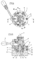
- FIG. 4 shows a plan view of a base plate (2) with hand lever (3), which is used to connect the Bottom insert (37) with the lifting device (38) is provided.
- To connect the base plate (2) with the bottom insert (37) has the base plate (2) Coupling element (4), which in a counter-element (5) the bottom insert (37) engages.
- the coupling element (4) and the counter element (5) together form one Coupling profile (22) off.
- the bottom insert (37) is shown in the illustrated Embodiment with hollow coupling plugs (6) provided in self-sealing sockets (7) of Engage base plate (2).
- the coupling plug (6) and the jacks (7) are used for feeding and Derivation of a temperature control medium in the area of Ground insert (37).
- Coupling plug (6) in the area of the base plate (2) and the bushes (7) in the area of the bottom insert (37) position is also conceivable that Coupling plug (6) in the area of the base plate (2) and the bushes (7) in the area of the bottom insert (37) position.
- Fig. 4 also shows the arrangement of Biasing elements (8) in a locked state the bottom insert (7) a backlash guarantee.
- the biasing elements (8) can For example, as disc springs, compression springs or Spiral springs to be formed.
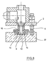
- the main body (9) is in the direction of a Longitudinal axis (11) in a guide (12) displaceable stored and the inclined edges (10) act with balls (14) together, which are arranged in an angle Guiding recesses (15) of the base body (9) stored are.
- the movement of the base body (9) in the direction of Longitudinal axis (11) is determined by a rotational movement of the Hand lever (3) caused, wherein the rotational movement of the hand lever (3) via a deflection (17) on the Basic bodies (9) is transmitted.
- the support plate (21) or the bottom insert (37) with a Connecting column to be provided in the base plate (2) protrudes and in the direction of its longitudinal axis at least one undercut is provided.
- the Undercut for example, as a lateral Notch or cutout be realized.
- a locking element is positioned in that in a locked state in the profile of the connecting column engages and to a positive connection between the base plate (2) and the support plate (21) or the Bottom insert (37) leads.
- a sufficient Backlash is also in this embodiment ensured by prestressing elements (8).
- the Locking element can, for example, as a Bolt segment be realized. Both the shape of the undercut profile of the connection column as but also the design of the locking element are often variable. It's just for one adequate adaptation of the respective shape designs to take care of each other.
- the biasing elements (8) in are formed essentially bolt-shaped and between Contact pressure flanks (18, 19) have spring elements (20), in an assembly of the base plate (2) and the Ground insert (37) are compressed. Also can be seen that the bottom insert (37) a Has support plate (21) corresponding to the contouring of the Container used (13) used in the bottom mold used in the shown illustration is not shown.
- Fig. 6 shows the hand lever (3) in solid lines in a release position and in dashed lines in the corresponding to Fig. 5 Arret michsposition réelle. It is from Fig. 6 recognizable that the main body (9) from the guide (12) is pushed out and that thereby the balls (14) to slide so deeply into the guide recesses (15) could that no more undercut with the collar (16). In this positioning, the Bottom insert (37) removed from the base plate (2) become.
- Fig. 7 shows in an enlarged and rotated Representation of the interaction of the pressure flanks (18, 19), the biasing elements (8) and the associated Spring elements (20).
- Fig. 8 again illustrates the positioning of Main body (9) relative to the guide (12) in one Condition in which the bottom insert (37) of the Base plate (2) can be removed.
- the arrangement of the biasing elements (8) takes place preferably with only a small distance to an outer periphery of the base plate (2) respectively of the bottom insert (37) to provide an additional safeguard to provide for a tilt. Under a small distance is understood here that the Distance of the biasing elements (8) to the outer periphery of Base plate (2) less than the distance to the Coupling profile (22) is dimensioned.
- the usage the drawn in the embodiments three Preload elements (8) also contributes to one increased tilting security at.
Landscapes
- Engineering & Computer Science (AREA)
- Mechanical Engineering (AREA)
- Manufacturing & Machinery (AREA)
- Blow-Moulding Or Thermoforming Of Plastics Or The Like (AREA)
- Moulds For Moulding Plastics Or The Like (AREA)
- Control And Other Processes For Unpacking Of Materials (AREA)
Claims (11)
- Dispositif pour le moulage par soufflage de récipients (13) à partir d'une matière thermoplastique, qui présente au moins un poste de soufflage (33) avec au moins un moule de soufflage (34), qui est constitué d'au moins deux segments (35, 36) de moule de soufflage supportés par des supports (48, 49), et qui présente un insert de fond (37) qui est agencé de manière à pouvoir être positionné dans la direction d'un axe longitudinal du moule de soufflage (34), et qui est maintenu par une plaque de base (2) qui relie l'insert de fond (37) à un moyen de positionnement, caractérisé en ce que la plaque de base (2) est reliée à l'insert de fond (37) par une section de couplage profilée (22) qui est constituée d'un organe de couplage (4) relié à la plaque de base (2), de même que d'un contre-organe (5) relié à l'insert de fond (37), et peut être actionnée par un levier manuel (3), et en ce qu'au moins deux chevilles d'accouplement creuses (6) sont agencées à distance de la section de couplage profilée (22), lesquelles peuvent être introduites dans des douilles de couplage (7) auto-scellantes.
- Dispositif selon la revendication 1, caractérisé en ce que l'organe de couplage (4) est réalisé expansible.
- Dispositif selon la revendication 1 ou 2, caractérisé en ce que l'organe de couplage (4) présente au moins un flanc oblique (10) qui positionne au moins une bille (14) perpendiculairement par rapport à un axe longitudinal (11).
- Dispositif selon l'une des revendications 1 à 3, caractérisé en ce que l'organe de couplage (4) est formé essentiellement d'un corps de base (9) et d'un guide (12) supportant le corps de base (9) de manière mobile dans la direction de l'axe longitudinal (11), et en ce que le guide (12) présente au moins un évidement (15) orienté en oblique par rapport à l'axe longitudinal (11), pour recevoir au moins une bille (14).
- Dispositif selon l'une des revendications 1 à 4, caractérisé en ce que la plaque de base (2) présente au moins un contre une rotation, pour définir un positionnement par rapport à l'insert de fond (37).
- Dispositif selon la revendication 5, caractérisé en ce que le moyen de sécurité contre une rotation est réalisé sous la forme d'un profil en saillie, qui peut être introduit dans un contre-profil.
- Dispositif selon la revendication 5, caractérisé en ce qu'un dispositif d'orientation du moule de base est formé par une disposition asymétrique des chevilles d'accouplement (6).
- Dispositif selon l'une des revendications 1 à 7, caractérisé en ce que les chevilles d'accouplement (6) sont réalisées sous la forme d'une partie d'une alimentation en eau.
- Dispositif selon l'une des revendications 1 à 8, caractérisé en ce qu'au moins un organe de précontrainte (8) est agencé à distance de la section de couplage profilée (22).
- Dispositif selon la revendication 9, caractérisé en ce qu'au moins trois organes de précontrainte (8) sont agencés à distance de la section de couplage profilée (22).
- Dispositif selon la revendication 9 ou 10, caractérisé en ce que les organes de précontrainte (8) sont agencés à faible distance d'une périphérie de la plaque de base (2).
Applications Claiming Priority (3)
| Application Number | Priority Date | Filing Date | Title |
|---|---|---|---|
| DE10033412A DE10033412B4 (de) | 2000-07-08 | 2000-07-08 | Vorrichtung zur Blasformung von Behältern |
| DE10033412 | 2000-07-08 | ||
| PCT/DE2001/002395 WO2002004194A1 (fr) | 2000-07-08 | 2001-07-06 | Dispositif pour le moulage de contenants par soufflage |
Publications (2)
| Publication Number | Publication Date |
|---|---|
| EP1299223A1 EP1299223A1 (fr) | 2003-04-09 |
| EP1299223B1 true EP1299223B1 (fr) | 2005-02-16 |
Family
ID=7648371
Family Applications (1)
| Application Number | Title | Priority Date | Filing Date |
|---|---|---|---|
| EP01953819A Expired - Lifetime EP1299223B1 (fr) | 2000-07-08 | 2001-07-06 | Dispositif pour le moulage de contenants par soufflage |
Country Status (6)
| Country | Link |
|---|---|
| US (1) | US7037099B2 (fr) |
| EP (1) | EP1299223B1 (fr) |
| AT (1) | ATE289256T1 (fr) |
| AU (1) | AU2001276285A1 (fr) |
| DE (2) | DE10033412B4 (fr) |
| WO (1) | WO2002004194A1 (fr) |
Cited By (7)
| Publication number | Priority date | Publication date | Assignee | Title |
|---|---|---|---|---|
| EP2279849A2 (fr) | 2009-07-31 | 2011-02-02 | Krones AG | Mécanisme de changement rapide pour éléments au sol |
| DE102010048720A1 (de) | 2010-10-19 | 2012-04-19 | Krones Aktiengesellschaft | Schnellmontierbare Bodenform mit zuschaltbarer Haltekraftunterstützung |
| DE102013113361A1 (de) | 2013-12-03 | 2015-06-03 | Krones Ag | Blasformmaschine mit am Blasrad angeordneten Austauschelementen |
| DE102014105762A1 (de) | 2014-04-24 | 2015-11-12 | Krones Ag | Blasformmaschine mit automatisch betätigbarer Bodenankopplung |
| DE102015117273A1 (de) | 2015-10-09 | 2017-04-13 | Krones Ag | Blasformmaschine mit automatisch betätigbarer Bodenankopplung |
| DE102015117292A1 (de) | 2015-10-09 | 2017-04-13 | Krones Ag | Blasformmaschine mit automatisch betätigbarer Bodenankopplung |
| EP3498451A2 (fr) | 2015-10-09 | 2019-06-19 | Krones AG | Machine de moulage par soufflage à accouplement de sol pouvant être actionné automatiquement et procédé pour le fonctionnement du dispositif associé |
Families Citing this family (22)
| Publication number | Priority date | Publication date | Assignee | Title |
|---|---|---|---|---|
| DE10242086A1 (de) | 2002-09-11 | 2004-04-15 | Sig Technology Ltd. | Behälter zur Verpackung von Produkten, Vorrichtung zur Verarbeitung von Kunstoff sowie Verfahren zur Behälterherstellung |
| US7318945B2 (en) | 2003-07-09 | 2008-01-15 | Medtronic Vascular, Inc. | Laminated drug-polymer coated stent having dipped layers |
| WO2006081653A1 (fr) * | 2005-02-01 | 2006-08-10 | Siemens Canada Limited | Soupape rge electrique a cout optimise |
| US10457437B2 (en) | 2006-03-06 | 2019-10-29 | Plastipak Packaging, Inc. | Lightweight plastic container and preform |
| US8857637B2 (en) | 2006-03-06 | 2014-10-14 | Plastipak Packaging, Inc. | Lightweight plastic container and preform |
| FR2903932B1 (fr) | 2006-07-21 | 2008-10-24 | Sidel Participations | Dispositif de fabrication de recipients comprenant un moule et une fiche de raccordement fluidique. |
| US8206143B2 (en) * | 2007-12-13 | 2012-06-26 | Biomet Manufacturing Corp. | Modular articulating cement spacer |
| US8057210B2 (en) * | 2009-04-29 | 2011-11-15 | Visy R & D Pty Ltd | Mould insert |
| FR2945469B1 (fr) * | 2009-05-14 | 2011-06-10 | Sidel Participations | Support de moule pour fond boxe |
| DE102010035496A1 (de) * | 2010-08-25 | 2012-03-01 | Krones Aktiengesellschaft | Fördervorrichtung zum Fördern von Vorformlingen |
| CN103402736A (zh) * | 2010-10-13 | 2013-11-20 | Khs科波普拉斯特有限责任公司 | 用于吹塑成型容器的方法和设备 |
| ITRM20110126A1 (it) | 2011-03-16 | 2012-09-17 | Sipa Progettazione Automaz | Stampo di soffiaggio |
| MX338900B (es) | 2011-10-26 | 2016-05-03 | Tpc Group Llc | Poliisobutileno preparado a alta velocidad y tasa de circulacion. |
| KR101929082B1 (ko) | 2011-10-26 | 2018-12-13 | 티피씨 그룹 엘엘씨 | 낮은 희석제 함량 반응 매질로 제조된 폴리아이소부틸렌 |
| US9309339B2 (en) | 2011-10-26 | 2016-04-12 | Tpc Group Llc | Mid-range vinylidene content, high viscosity polyisobutylene polymers |
| FR2983766B1 (fr) * | 2011-12-08 | 2014-02-14 | Sidel Participations | Ensemble pour la fixation, avec raccordement fluidique, d'un fond de moule sur un support |
| US9545301B2 (en) | 2013-03-15 | 2017-01-17 | Covidien Lp | Coated medical devices and methods of making and using same |
| CN103171139B (zh) * | 2013-03-19 | 2014-12-31 | 江苏新美星包装机械股份有限公司 | 一种单轴开合模、底模锁定联动机构 |
| US9617363B1 (en) | 2016-03-03 | 2017-04-11 | Tpc Group Llc | Low-fluoride, reactive polyisobutylene |
| US9617366B1 (en) | 2016-03-03 | 2017-04-11 | Tpc Group Llc | Low-fluoride, reactive polyisobutylene |
| WO2017151341A1 (fr) | 2016-03-03 | 2017-09-08 | Tpc Group Llc | Polyisobutylène réactif à faible teneur en fluorures |
| EP3661725B1 (fr) | 2017-08-02 | 2022-01-19 | Krones AG | Changement de moule de soufflage automatique |
Family Cites Families (12)
| Publication number | Priority date | Publication date | Assignee | Title |
|---|---|---|---|---|
| DE2352926A1 (de) | 1973-10-22 | 1975-04-24 | Heidenreich & Harbeck Gmbh | Verfahren und vorrichtung zum erwaermen eines werkstueckes aus kunststoff |
| US4839127A (en) * | 1987-03-04 | 1989-06-13 | Owens-Illinois Plastic Products Inc. | Method of making partially crystalline biaxially oriented hollow plastic heat set containers |
| CA1327110C (fr) * | 1988-04-28 | 1994-02-22 | Tatsuzi Nakagawa | Moule et methode de pose et d'extraction de matrices et d'ejection de la piece moulee |
| US5255889A (en) * | 1991-11-15 | 1993-10-26 | Continental Pet Technologies, Inc. | Modular wold |
| DE4212583A1 (de) | 1992-04-15 | 1993-10-21 | Krupp Corpoplast Masch | Vorrichtung zur Blasformung |
| DE4340291A1 (de) | 1993-11-26 | 1995-06-01 | Krupp Corpoplast Masch | Mehrfachnutzung von Blasluft |
| FR2720680A1 (fr) * | 1994-06-03 | 1995-12-08 | Sidel Sa | Dispositif de fixation pour fond de moule pour une machine de fabrication de récipients à partir de préformes et machine de fabrication de récipients en plastique facilement personnalisable. |
| AUPN496195A0 (en) * | 1995-08-22 | 1995-09-14 | Aci Operations Pty. Limited | Improved process for mould replacement |
| US5762981A (en) * | 1996-09-10 | 1998-06-09 | Wentworth Mould And Die Company Limited | Base for a mold assembly |
| DE19909644A1 (de) * | 1999-03-05 | 2000-09-07 | Krupp Corpoplast Masch | Verfahren und Vorrichtung zur Blasformung von Behältern |
| DE19925756A1 (de) * | 1999-06-05 | 2000-12-07 | Krupp Corpoplast Maschb Gmbh | Verfahren und Vorrichtung zur Blasformung von Behältern |
| DE19934320A1 (de) * | 1999-07-21 | 2001-01-25 | Krupp Corpoplast Maschb Gmbh | Verfahren und Vorrichtung zur Blasformung von Behältern |
-
2000
- 2000-07-08 DE DE10033412A patent/DE10033412B4/de not_active Expired - Lifetime
-
2001
- 2001-07-06 US US10/332,389 patent/US7037099B2/en not_active Expired - Lifetime
- 2001-07-06 AU AU2001276285A patent/AU2001276285A1/en not_active Abandoned
- 2001-07-06 DE DE50105378T patent/DE50105378D1/de not_active Expired - Lifetime
- 2001-07-06 AT AT01953819T patent/ATE289256T1/de not_active IP Right Cessation
- 2001-07-06 WO PCT/DE2001/002395 patent/WO2002004194A1/fr not_active Ceased
- 2001-07-06 EP EP01953819A patent/EP1299223B1/fr not_active Expired - Lifetime
Cited By (14)
| Publication number | Priority date | Publication date | Assignee | Title |
|---|---|---|---|---|
| EP2279849A2 (fr) | 2009-07-31 | 2011-02-02 | Krones AG | Mécanisme de changement rapide pour éléments au sol |
| DE102009035871A1 (de) | 2009-07-31 | 2011-02-03 | Krones Ag | Schnellwechselmechansimus für Bodenteile |
| EP3530432B1 (fr) | 2009-07-31 | 2023-10-04 | Krones AG | Mécanisme de changement rapide pour parties de fond |
| EP3530432A1 (fr) | 2009-07-31 | 2019-08-28 | Krones AG | Mécanisme de changement rapide pour parties de fond |
| US8408893B2 (en) | 2009-07-31 | 2013-04-02 | Krones Ag | Rapid changeover mechanism for bottom portions |
| EP2279849A3 (fr) * | 2009-07-31 | 2014-05-07 | Krones AG | Mécanisme de changement rapide pour éléments au sol |
| EP2444233A3 (fr) * | 2010-10-19 | 2014-05-21 | Krones AG | Dispositif de formage par soufflage avec dispositif de serrage du moule et un procédé |
| EP2444233A2 (fr) | 2010-10-19 | 2012-04-25 | Krones AG | Dispositif de formage par soufflage avec dispositif de serrage du moule et un procédé |
| DE102010048720A1 (de) | 2010-10-19 | 2012-04-19 | Krones Aktiengesellschaft | Schnellmontierbare Bodenform mit zuschaltbarer Haltekraftunterstützung |
| DE102013113361A1 (de) | 2013-12-03 | 2015-06-03 | Krones Ag | Blasformmaschine mit am Blasrad angeordneten Austauschelementen |
| DE102014105762A1 (de) | 2014-04-24 | 2015-11-12 | Krones Ag | Blasformmaschine mit automatisch betätigbarer Bodenankopplung |
| DE102015117273A1 (de) | 2015-10-09 | 2017-04-13 | Krones Ag | Blasformmaschine mit automatisch betätigbarer Bodenankopplung |
| DE102015117292A1 (de) | 2015-10-09 | 2017-04-13 | Krones Ag | Blasformmaschine mit automatisch betätigbarer Bodenankopplung |
| EP3498451A2 (fr) | 2015-10-09 | 2019-06-19 | Krones AG | Machine de moulage par soufflage à accouplement de sol pouvant être actionné automatiquement et procédé pour le fonctionnement du dispositif associé |
Also Published As
| Publication number | Publication date |
|---|---|
| ATE289256T1 (de) | 2005-03-15 |
| WO2002004194A1 (fr) | 2002-01-17 |
| DE10033412B4 (de) | 2012-05-24 |
| DE50105378D1 (de) | 2005-03-24 |
| DE10033412A1 (de) | 2002-01-17 |
| EP1299223A1 (fr) | 2003-04-09 |
| US7037099B2 (en) | 2006-05-02 |
| US20040052892A1 (en) | 2004-03-18 |
| AU2001276285A1 (en) | 2002-01-21 |
Similar Documents
| Publication | Publication Date | Title |
|---|---|---|
| EP1299223B1 (fr) | Dispositif pour le moulage de contenants par soufflage | |
| EP1312459B1 (fr) | Dispositif pour le moulage de récipients par soufflage | |
| EP1858689B1 (fr) | Dispositif de moulage par soufflage de recipients | |
| EP2753465B1 (fr) | Dispositif de transport de preformes pour le moulage par soufflage de recipients | |
| EP1535719B1 (fr) | Dispositif pour mouler des récipients par soufflage | |
| DE102014017546B4 (de) | Anordnung zum Haltern von Werkstücken, Vorrichtung mit einer solchen Anordnung und Verwendung einer solchen Anordnung | |
| DE102017124186B4 (de) | Transportsystem zum Transport von Vorformlingen sowie Vorrichtung mit Transportsystem und Verwendung eines Transportsystems | |
| DE19948474B4 (de) | Verfahren und Vorrichtung zur Blasformung von Behältern | |
| DE112006000800B4 (de) | Verfahren und Vorrichtung zur Blasformung von Behältern unter Verwendung eines beweglich geführten Ventilträgers | |
| WO2000074925A1 (fr) | Procede et dispositif de soufflage de contenants au moyen d'un moule de fond refroidi de maniere rayonnante | |
| EP1254015B1 (fr) | Procede et dispositif de transport d'elements de support | |
| EP2129508B1 (fr) | Procédé de moulage par soufflage de contenants | |
| DE10146232A1 (de) | Vorrichtung zur Handhabung von Behältern | |
| WO2005097466A1 (fr) | Procede et dispositif de moulage de contenants par soufflage, faisant appel a une vitesse d'augmentation de pression reduite | |
| EP3064334A1 (fr) | Procédé et dispositif de chauffage destiné à déterminer la température d'ébauches et machine de moulage par soufflage comprenant un tel dispositif | |
| DE102005011804A1 (de) | Verfahren und Vorrichtung zur Blasformung von Behältern | |
| DE10355365A1 (de) | Vorrichtung zur Blasformung von Behältern | |
| DE102005059057A1 (de) | Verfahren und Vorrichtung zur Blasformung von Behältern | |
| EP1230079B1 (fr) | Procede et dispositif de formage par soufflage de recipients | |
| EP1473139A1 (fr) | Procédé et appareil de formage de récipients par soufflage | |
| EP2768654B1 (fr) | Dispositif de retenue de pièces |
Legal Events
| Date | Code | Title | Description |
|---|---|---|---|
| PUAI | Public reference made under article 153(3) epc to a published international application that has entered the european phase |
Free format text: ORIGINAL CODE: 0009012 |
|
| 17P | Request for examination filed |
Effective date: 20021113 |
|
| AK | Designated contracting states |
Designated state(s): AT BE CH CY DE DK ES FI FR GB GR IE IT LI LU MC NL PT SE TR Kind code of ref document: A1 Designated state(s): AT BE CH CY DE DK ES FI FR GB GR IE IT LI LU MC NL PT SE TR |
|
| AX | Request for extension of the european patent |
Extension state: AL LT LV MK RO SI |
|
| 17Q | First examination report despatched |
Effective date: 20040421 |
|
| GRAP | Despatch of communication of intention to grant a patent |
Free format text: ORIGINAL CODE: EPIDOSNIGR1 |
|
| GRAS | Grant fee paid |
Free format text: ORIGINAL CODE: EPIDOSNIGR3 |
|
| GRAA | (expected) grant |
Free format text: ORIGINAL CODE: 0009210 |
|
| AK | Designated contracting states |
Kind code of ref document: B1 Designated state(s): AT BE CH CY DE DK ES FI FR GB GR IE IT LI LU MC NL PT SE TR |
|
| PG25 | Lapsed in a contracting state [announced via postgrant information from national office to epo] |
Ref country code: IE Free format text: LAPSE BECAUSE OF FAILURE TO SUBMIT A TRANSLATION OF THE DESCRIPTION OR TO PAY THE FEE WITHIN THE PRESCRIBED TIME-LIMIT Effective date: 20050216 Ref country code: FI Free format text: LAPSE BECAUSE OF FAILURE TO SUBMIT A TRANSLATION OF THE DESCRIPTION OR TO PAY THE FEE WITHIN THE PRESCRIBED TIME-LIMIT Effective date: 20050216 Ref country code: GB Free format text: LAPSE BECAUSE OF FAILURE TO SUBMIT A TRANSLATION OF THE DESCRIPTION OR TO PAY THE FEE WITHIN THE PRESCRIBED TIME-LIMIT Effective date: 20050216 Ref country code: NL Free format text: LAPSE BECAUSE OF FAILURE TO SUBMIT A TRANSLATION OF THE DESCRIPTION OR TO PAY THE FEE WITHIN THE PRESCRIBED TIME-LIMIT Effective date: 20050216 Ref country code: TR Free format text: LAPSE BECAUSE OF FAILURE TO SUBMIT A TRANSLATION OF THE DESCRIPTION OR TO PAY THE FEE WITHIN THE PRESCRIBED TIME-LIMIT Effective date: 20050216 |
|
| REG | Reference to a national code |
Ref country code: GB Ref legal event code: FG4D Free format text: NOT ENGLISH |
|
| REG | Reference to a national code |
Ref country code: CH Ref legal event code: EP |
|
| REG | Reference to a national code |
Ref country code: IE Ref legal event code: FG4D Free format text: GERMAN |
|
| REF | Corresponds to: |
Ref document number: 50105378 Country of ref document: DE Date of ref document: 20050324 Kind code of ref document: P |
|
| PG25 | Lapsed in a contracting state [announced via postgrant information from national office to epo] |
Ref country code: SE Free format text: LAPSE BECAUSE OF FAILURE TO SUBMIT A TRANSLATION OF THE DESCRIPTION OR TO PAY THE FEE WITHIN THE PRESCRIBED TIME-LIMIT Effective date: 20050516 Ref country code: DK Free format text: LAPSE BECAUSE OF FAILURE TO SUBMIT A TRANSLATION OF THE DESCRIPTION OR TO PAY THE FEE WITHIN THE PRESCRIBED TIME-LIMIT Effective date: 20050516 Ref country code: GR Free format text: LAPSE BECAUSE OF FAILURE TO SUBMIT A TRANSLATION OF THE DESCRIPTION OR TO PAY THE FEE WITHIN THE PRESCRIBED TIME-LIMIT Effective date: 20050516 |
|
| PG25 | Lapsed in a contracting state [announced via postgrant information from national office to epo] |
Ref country code: ES Free format text: LAPSE BECAUSE OF FAILURE TO SUBMIT A TRANSLATION OF THE DESCRIPTION OR TO PAY THE FEE WITHIN THE PRESCRIBED TIME-LIMIT Effective date: 20050527 |
|
| PG25 | Lapsed in a contracting state [announced via postgrant information from national office to epo] |
Ref country code: LU Free format text: LAPSE BECAUSE OF NON-PAYMENT OF DUE FEES Effective date: 20050706 Ref country code: CY Free format text: LAPSE BECAUSE OF FAILURE TO SUBMIT A TRANSLATION OF THE DESCRIPTION OR TO PAY THE FEE WITHIN THE PRESCRIBED TIME-LIMIT Effective date: 20050706 Ref country code: AT Free format text: LAPSE BECAUSE OF NON-PAYMENT OF DUE FEES Effective date: 20050706 |
|
| PG25 | Lapsed in a contracting state [announced via postgrant information from national office to epo] |
Ref country code: PT Free format text: LAPSE BECAUSE OF FAILURE TO SUBMIT A TRANSLATION OF THE DESCRIPTION OR TO PAY THE FEE WITHIN THE PRESCRIBED TIME-LIMIT Effective date: 20050722 |
|
| PG25 | Lapsed in a contracting state [announced via postgrant information from national office to epo] |
Ref country code: CH Free format text: LAPSE BECAUSE OF NON-PAYMENT OF DUE FEES Effective date: 20050731 Ref country code: MC Free format text: LAPSE BECAUSE OF NON-PAYMENT OF DUE FEES Effective date: 20050731 Ref country code: LI Free format text: LAPSE BECAUSE OF NON-PAYMENT OF DUE FEES Effective date: 20050731 Ref country code: BE Free format text: LAPSE BECAUSE OF NON-PAYMENT OF DUE FEES Effective date: 20050731 |
|
| NLV1 | Nl: lapsed or annulled due to failure to fulfill the requirements of art. 29p and 29m of the patents act | ||
| GBV | Gb: ep patent (uk) treated as always having been void in accordance with gb section 77(7)/1977 [no translation filed] |
Effective date: 20050216 |
|
| REG | Reference to a national code |
Ref country code: IE Ref legal event code: FD4D |
|
| PLBE | No opposition filed within time limit |
Free format text: ORIGINAL CODE: 0009261 |
|
| STAA | Information on the status of an ep patent application or granted ep patent |
Free format text: STATUS: NO OPPOSITION FILED WITHIN TIME LIMIT |
|
| 26N | No opposition filed |
Effective date: 20051117 |
|
| ET | Fr: translation filed | ||
| REG | Reference to a national code |
Ref country code: CH Ref legal event code: PL |
|
| BERE | Be: lapsed |
Owner name: SIG CORPOPLAST G.M.B.H. & CO. KG Effective date: 20050731 |
|
| REG | Reference to a national code |
Ref country code: FR Ref legal event code: CD |
|
| REG | Reference to a national code |
Ref country code: DE Ref legal event code: R081 Ref document number: 50105378 Country of ref document: DE Owner name: KHS CORPOPLAST GMBH, DE Free format text: FORMER OWNER: KHS CORPOPLAST GMBH & CO. KG, 22145 HAMBURG, DE Effective date: 20110504 |
|
| REG | Reference to a national code |
Ref country code: DE Ref legal event code: R082 Ref document number: 50105378 Country of ref document: DE |
|
| REG | Reference to a national code |
Ref country code: FR Ref legal event code: PLFP Year of fee payment: 16 |
|
| REG | Reference to a national code |
Ref country code: FR Ref legal event code: PLFP Year of fee payment: 17 |
|
| REG | Reference to a national code |
Ref country code: FR Ref legal event code: PLFP Year of fee payment: 18 |
|
| PGFP | Annual fee paid to national office [announced via postgrant information from national office to epo] |
Ref country code: DE Payment date: 20200721 Year of fee payment: 20 Ref country code: FR Payment date: 20200721 Year of fee payment: 20 |
|
| PGFP | Annual fee paid to national office [announced via postgrant information from national office to epo] |
Ref country code: IT Payment date: 20200724 Year of fee payment: 20 |
|
| REG | Reference to a national code |
Ref country code: DE Ref legal event code: R071 Ref document number: 50105378 Country of ref document: DE |