EP1299254B1 - Reifen mit verbessertem karkassenverankern - Google Patents
Reifen mit verbessertem karkassenverankern Download PDFInfo
- Publication number
- EP1299254B1 EP1299254B1 EP01945313A EP01945313A EP1299254B1 EP 1299254 B1 EP1299254 B1 EP 1299254B1 EP 01945313 A EP01945313 A EP 01945313A EP 01945313 A EP01945313 A EP 01945313A EP 1299254 B1 EP1299254 B1 EP 1299254B1
- Authority
- EP
- European Patent Office
- Prior art keywords
- reinforcing threads
- bead
- carcass reinforcement
- reinforcements
- tyre
- Prior art date
- Legal status (The legal status is an assumption and is not a legal conclusion. Google has not performed a legal analysis and makes no representation as to the accuracy of the status listed.)
- Expired - Lifetime
Links
- 230000002787 reinforcement Effects 0.000 title claims abstract description 128
- 238000004873 anchoring Methods 0.000 title description 6
- 239000011324 bead Substances 0.000 claims abstract description 56
- 230000003014 reinforcing effect Effects 0.000 claims abstract description 28
- 229920003235 aromatic polyamide Polymers 0.000 claims description 13
- 239000004760 aramid Substances 0.000 claims description 12
- 241000531908 Aramides Species 0.000 description 7
- 239000000203 mixture Substances 0.000 description 6
- 239000000835 fiber Substances 0.000 description 4
- 229910000831 Steel Inorganic materials 0.000 description 3
- 239000000853 adhesive Substances 0.000 description 3
- 230000001070 adhesive effect Effects 0.000 description 3
- 239000011159 matrix material Substances 0.000 description 3
- 238000002156 mixing Methods 0.000 description 3
- 239000010959 steel Substances 0.000 description 3
- 230000000712 assembly Effects 0.000 description 2
- 238000000429 assembly Methods 0.000 description 2
- 239000011248 coating agent Substances 0.000 description 2
- 238000000576 coating method Methods 0.000 description 2
- 238000010438 heat treatment Methods 0.000 description 2
- 238000004519 manufacturing process Methods 0.000 description 2
- 238000000034 method Methods 0.000 description 2
- 238000004073 vulcanization Methods 0.000 description 2
- 238000004804 winding Methods 0.000 description 2
- 229910001369 Brass Inorganic materials 0.000 description 1
- CBENFWSGALASAD-UHFFFAOYSA-N Ozone Chemical compound [O-][O+]=O CBENFWSGALASAD-UHFFFAOYSA-N 0.000 description 1
- 239000010951 brass Substances 0.000 description 1
- 230000000295 complement effect Effects 0.000 description 1
- 239000002131 composite material Substances 0.000 description 1
- 230000006835 compression Effects 0.000 description 1
- 238000007906 compression Methods 0.000 description 1
- 239000000470 constituent Substances 0.000 description 1
- 238000010411 cooking Methods 0.000 description 1
- 238000005336 cracking Methods 0.000 description 1
- 230000007423 decrease Effects 0.000 description 1
- 239000012528 membrane Substances 0.000 description 1
- 239000002184 metal Substances 0.000 description 1
- 238000002360 preparation method Methods 0.000 description 1
- 238000011084 recovery Methods 0.000 description 1
- 238000005096 rolling process Methods 0.000 description 1
- 238000004513 sizing Methods 0.000 description 1
- 230000000087 stabilizing effect Effects 0.000 description 1
Images

Classifications
-
- B—PERFORMING OPERATIONS; TRANSPORTING
- B60—VEHICLES IN GENERAL
- B60C—VEHICLE TYRES; TYRE INFLATION; TYRE CHANGING; CONNECTING VALVES TO INFLATABLE ELASTIC BODIES IN GENERAL; DEVICES OR ARRANGEMENTS RELATED TO TYRES
- B60C15/00—Tyre beads, e.g. ply turn-up or overlap
- B60C15/06—Flipper strips, fillers, or chafing strips and reinforcing layers for the construction of the bead
-
- B—PERFORMING OPERATIONS; TRANSPORTING
- B60—VEHICLES IN GENERAL
- B60C—VEHICLE TYRES; TYRE INFLATION; TYRE CHANGING; CONNECTING VALVES TO INFLATABLE ELASTIC BODIES IN GENERAL; DEVICES OR ARRANGEMENTS RELATED TO TYRES
- B60C15/00—Tyre beads, e.g. ply turn-up or overlap
- B60C15/0009—Tyre beads, e.g. ply turn-up or overlap features of the carcass terminal portion
- B60C15/0018—Tyre beads, e.g. ply turn-up or overlap features of the carcass terminal portion not folded around the bead core, e.g. floating or down ply
-
- B—PERFORMING OPERATIONS; TRANSPORTING
- B60—VEHICLES IN GENERAL
- B60C—VEHICLE TYRES; TYRE INFLATION; TYRE CHANGING; CONNECTING VALVES TO INFLATABLE ELASTIC BODIES IN GENERAL; DEVICES OR ARRANGEMENTS RELATED TO TYRES
- B60C15/00—Tyre beads, e.g. ply turn-up or overlap
- B60C15/04—Bead cores
- B60C15/05—Bead cores multiple, i.e. with two or more cores in each bead
-
- B—PERFORMING OPERATIONS; TRANSPORTING
- B60—VEHICLES IN GENERAL
- B60C—VEHICLE TYRES; TYRE INFLATION; TYRE CHANGING; CONNECTING VALVES TO INFLATABLE ELASTIC BODIES IN GENERAL; DEVICES OR ARRANGEMENTS RELATED TO TYRES
- B60C9/00—Reinforcements or ply arrangement of pneumatic tyres
- B60C9/02—Carcasses
- B60C9/023—Carcasses built up from narrow strips, individual cords or filaments, e.g. using filament winding
-
- Y—GENERAL TAGGING OF NEW TECHNOLOGICAL DEVELOPMENTS; GENERAL TAGGING OF CROSS-SECTIONAL TECHNOLOGIES SPANNING OVER SEVERAL SECTIONS OF THE IPC; TECHNICAL SUBJECTS COVERED BY FORMER USPC CROSS-REFERENCE ART COLLECTIONS [XRACs] AND DIGESTS
- Y10—TECHNICAL SUBJECTS COVERED BY FORMER USPC
- Y10T—TECHNICAL SUBJECTS COVERED BY FORMER US CLASSIFICATION
- Y10T152/00—Resilient tires and wheels
- Y10T152/10—Tires, resilient
- Y10T152/10495—Pneumatic tire or inner tube
- Y10T152/10819—Characterized by the structure of the bead portion of the tire
- Y10T152/10846—Bead characterized by the chemical composition and or physical properties of elastomers or the like
-
- Y—GENERAL TAGGING OF NEW TECHNOLOGICAL DEVELOPMENTS; GENERAL TAGGING OF CROSS-SECTIONAL TECHNOLOGIES SPANNING OVER SEVERAL SECTIONS OF THE IPC; TECHNICAL SUBJECTS COVERED BY FORMER USPC CROSS-REFERENCE ART COLLECTIONS [XRACs] AND DIGESTS
- Y10—TECHNICAL SUBJECTS COVERED BY FORMER USPC
- Y10T—TECHNICAL SUBJECTS COVERED BY FORMER US CLASSIFICATION
- Y10T152/00—Resilient tires and wheels
- Y10T152/10—Tires, resilient
- Y10T152/10495—Pneumatic tire or inner tube
- Y10T152/10855—Characterized by the carcass, carcass material, or physical arrangement of the carcass materials
Definitions
- the invention relates to tires intended to carry heavy loads such as, for example, airplane tires.
- Aircraft tires must withstand extreme operating conditions, particularly in terms of applied load and speed given their low weight and size. As a result, despite their very high inflation pressures, greater than 12 bar, their crushing or deflection in service can currently reach values double those observed for heavy goods vehicles or tourism.
- US Patent 4,832,102 discloses an aircraft tire comprising a crown, two flanks and two beads, a carcass reinforcement and a crown reinforcement in which the carcass reinforcement comprises two circumferential alignments of reinforcements of high modulus of elasticity. , anchored in the two beads, and the crown reinforcement comprises at least one working block with at least one ply of reinforcements high modulus of elasticity.
- the carcass reinforcement is anchored in the beads by the overturning, around a bead wire, of the two circumferential alignments of first reinforcements of high modulus of elasticity.
- a tire according to these applications, comprises a bead with means for anchoring the carcass reinforcement. comprising circumferentially oriented reinforcements axially bordering the circumferential alignments of the reinforcements of the carcass reinforcement.
- the application WO 98/54006 proposes a tire whose carcass reinforcement comprises two or three circumferential alignments of reinforcements in which each circumferential alignment is bordered axially internally and externally by circumferentially oriented reinforcements. This application indicates for constituting the circumferential reinforcements many types of reinforcements.
- US-A-5,660,656 discloses a tire corresponding to the preamble of claim 1.
- the invention relates to a tire whose anchoring of the carcass reinforcement is improved.
- title means the mass in grams of a thousand meters of a reinforcement. The title is expressed in tex. The stress experienced by a reinforcement or the modulus of this reinforcement is expressed in "cN / tex", cN meaning centi-newton.
- reinforcement thread means any reinforcing element in the form of a wire, capable of reinforcing a specific matrix, for example a rubber matrix.
- reinforcements mention may be made, for example, of multifilament fibers ("multifilament yarns"), these fibers possibly being twisted or not on themselves, unitary yarns such as monofilaments of high elementary diameter, with or without torsion on them. the same, cords or twists (“cords”) obtained by cabling operations or twisting of these single son or these fibers, such reinforcements that can be hybrid, that is to say composites, comprising elements natures different.
- pllied yarn means a reinforcement constituted by two strands ("single yarns") or more assembled together by twisting operations; these strands, generally formed of multifilament fibers, are first twisted individually in one direction (S or Z twist direction) during a first twisting step, and then twisted together in the opposite direction (Z or S twist direction, respectively) during a second twisting step.
- adheresive reinforcement means a reinforcement having undergone a suitable coating treatment, called sizing or adhesion, capable of adhering this reinforcement, after a suitable heat treatment, to the matrix for which it is intended.
- axial means a direction parallel to the axis A of the tire; this direction can be “axially inner” when it is directed towards the inside of the tire and “axially outside” when it is directed towards the outside of the tire.
- radial means a direction perpendicular to the axis A of the tire and passing through this axis A. This direction may be “radially inner” or “radially outer” as it moves towards the axis A or towards the outside the tire.
- substantially circumferential orientation means an orientation that does not deviate by more than five degrees from the circumferential direction.
- modulus of elasticity of a rubber mix means a secant modulus of extension at 10% of deformation and at ambient temperature.
- the tire according to the invention comprises a crown, two flanks and two beads, a carcass reinforcement anchored in each of the beads and a crown reinforcement.
- the carcass reinforcement comprises at least two circumferential alignments of first reinforcements of high modulus of elasticity, each circumferential alignment of the first reinforcements being, in each bead, bordered axially internally and axially externally by second reinforcements oriented substantially circumferentially of modulus greater than or equal to that of the first reinforcements, the first reinforcements and second reinforcements being separated by a mixing layer of very high modulus of elasticity and such that, considering ⁇ R I sum of the extension stiffnesses of the second reinforcements arranged axially internally relative to the carcass reinforcement and considering ⁇ R E sum of the stiffnesses extension of the second reinforcements arranged axially on either side of the carcass reinforcement, we have: 0 , 6 ⁇ ⁇ ⁇ R I ⁇ ⁇ R E ⁇ 1 , 5 and preferably: 0 , 7 ⁇ ⁇ ⁇
- This embodiment of a bead is particularly suitable in the case where the seat of the bead is intended to rest against a rim seat slightly inclined relative to the axis A of the tire. This is the case for tires for aircraft, for heavy goods vehicles or for passenger vehicles whose inclination of the rim seats is of the order of 5 degrees.
- This line CD substantially defines a very rigid encasement zone where the deformations are very small and a flexural zone radially above CD. The fact that all the second reinforcements are in the embedding zone reinforces the endurance of the bead.
- the first reinforcements preferably have a secant modulus of extension greater than 1000 cN / Tex and such reinforcements are, for example, made of aromatic polyamide.
- the mixing layer of very high modulus of elasticity has a Shore A hardness greater than 70. It can also have a secant modulus of extension at 10% greater than 20 MPa and preferably greater than 30 MPa.
- the carcass reinforcement of the tires according to the invention comprise two or three circumferential alignments of reinforcements of high modulus of elasticity, of aromatic polyamide, for example.
- the bead of the tire according to the invention having an outer surface intended to come into contact with the corresponding surface of the seat and the hook of the rim, after mounting on said rim and inflating the tire, the contact zone between the surface.
- outer rim and the rim extends to the point B of the maximum radius hook R J.
- the first reinforcements of the carcass reinforcement form back and forth arranged adjacently, with, at each bead, loops connecting each time a go to a return.
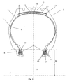
- the aircraft tire 1 represented diagrammatically in axial half-section in FIG. 1 comprises an apex 2, two flanks 3 and two beads 4.
- a carcass reinforcement 5 extends from one bead to the other and consists of two circumferential alignments 6 and 7 of first reinforcements.
- the circumferential alignments of first reinforcements 6 and 7 are oriented radially in the sidewalls 3 and consist of reinforcements of aromatic polyamide or aramid.
- the first reinforcements are arranged in parallel and are separated by a mixing layer 8 whose nature and the module are adapted according to their position in the tire.
- the anchoring of the two circumferential alignments 6 and 7 is ensured in the beads 3 by alignments or "stacks" 9 of second reinforcements oriented circumferentially and arranged axially on either side of each circumferential alignment of first reinforcements 6 and 7.
- alignment or stack 9 of second reinforcements may be obtained by helical winding of a reinforcement.
- the first reinforcements, radial, and second reinforcements, circumferential are separated from each other by a layer of rubber mix 10 of very high modulus of elasticity to avoid direct contact of a reinforcement with another.
- This layer 10 has a secant modulus of extension at 10% greater than 20 MPa and preferably 30 MPa. Its Shore A hardness is also greater than 70.
- the tension that develops in the first reinforcements during inflation of the tire 1 is taken up in particular by the lateral adhesion between each circumferential alignment 6 and 7 and the piles 9 of circumferential reinforcements.
- This bead structure provides excellent anchorage which remains very effective even for the very high inflation pressures of aircraft tires, greater than 12 bar and up to 25 bar in some particular applications.
- the stacks 9 of second reinforcements are divided into three groups, two stacks 11 arranged axially externally to the carcass reinforcement 5 on the outside of the tire, two stacks 13 arranged axially inwardly relative to the carcass reinforcement 5, on the inner side of the tire.
- pneumatic and 4 batteries 12 arranged between the two circumferential alignments 6 and 7 of the carcass reinforcement 5.
- the second reinforcement used in this tire is a monofilament or unit wire of 0.98 mm diameter steel. This reinforcement is of course adhered with a brass or zinc-plated coating. Its use makes it possible to obtain a very small footprint for a very high rigidity of extension of all the cells 9. Its cost is also reduced relative to the assemblies usually used in tires. It is also possible to replace these unitary son by metal assemblies well known in the field of tires.
- the number of turns of the stacks decreases progressively with the distance relative to the axis A of the tire 1. This results in a substantially conical shape of the arrangement of the second reinforcements. This has the advantage of strongly stabilizing the beads 4 during inflation of the tire and during passage into the contact area in service.
- the set of turns of the stacks 9 is embedded in the rubber mixture 10 of very high modulus of elasticity to ensure a good recovery of the forces due to the inflation pressure and thus an excellent anchoring of the carcass reinforcement in the beads 4 .
- FIG 2 is a perspective view of one of the circumferential alignments of first reinforcements, the alignment 6, in which only the reinforcements are shown.
- the circumferential alignment 6 of first reinforcements which consists of portions of reinforcements 17.
- the portions of reinforcements 17 form loops 18 juxtaposed, located in the bead 4. These loops 18 are adjacent and do not overlap.
- On either side axially of the circumferential alignment 6 of the first reinforcements are represented only the piles 11 and 12 directly adjacent to this alignment 6.
- the circumferential alignment 7 of the first reinforcements has the same arrangement of the reinforcing portions 17.
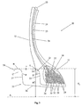
- FIG. 3 shows a bead 21 and a flank 22 of a second embodiment of a tire 20 according to the invention in which the carcass reinforcement 23 consists of three circumferential alignments, 24, 25, 26, reinforcements in aromatic polyamide or aramid.
- the carcass reinforcement 23 consists of three circumferential alignments, 24, 25, 26, reinforcements in aromatic polyamide or aramid.
- piles 27 of second reinforcements circumferentially oriented. These cells 27 are here separated into four groups.
- the second reinforcements consist of monofilaments or single son of steel and the number of turns is such that it is verified that the sum of the extension stiffnesses of the cells arranged externally relative to the carcass reinforcement is substantially equal to same order as the sum of the extension stiffnesses of the cells disposed internally relative to the carcass reinforcement 23.
- the outer surface of the bead 21 comprises a seat 32, a frustoconical wall of substantially radial orientation 33 adjacent radially inwardly to a wall 34 whose section is a circular arc EF of center C.
- C is disposed outside the bead 21
- the assembly second reinforcements 27 is disposed at a radial distance from the axis A less than or equal to this line CD.
- This line CD substantially defines a very rigid embedding zone where the deformations are very small and a flexural zone radially above CD. The fact that all the second reinforcements are in the embedding zone reinforces the endurance of the bead.
- This outer surface of the bead is intended to bear against the wall of a rim 35 whose outer profile is also shown in Figure 3.
- This profile comprises the seat 36 and the substantially radial wall of the hook 37 followed by the rim 38
- the rim 38 has a straight section in a circular arc of center C '.
- the highest point of radius is B, radius R J.
- the point E disposed on the axially outer surface of the bead 21 is intended to come into contact with substantially the point B.
- the surfaces 34 and 38 are homocentric, that is to say that their centers C and C 'are merged.
- FIG. 1 also shows an exemplary crown reinforcement 14. It consists of a work block comprising two plies of reinforcements 15 and 16 of substantially circumferential orientation obtained by helical winding of at least one reinforcement .
- This reinforcement consists of reinforcements of aromatic polyamide or aramid. The number of reinforcing plies and the pitch are adapted according to the size of the tire and its conditions of use.
- This embodiment of a crown reinforcement has the advantage of providing a very effective hooping which minimizes the variation of the dimensions of the tire during inflation as well as at high speed. It can be seen that the evolution of the profile can be three to four times lower than for a common aircraft tire such as a 30-7.7R16 AIRX. This excellent hooping also has the advantage of not putting in strong extension mixtures constituting the tread of the top of the tire. The surface cracking of the tread due to ozone in the air is greatly reduced.
- This tire underwent burst resistance tests and the maximum pressures measured were of the order of 100 bars. It is also characterized by a rate of elongation of its development between the zero pressure and its operating pressure of 15 bar of the order of 1.5%. This tire has also successfully passed take-off tests similar to the standardized tests for the approval of aircraft tires.
- the preparation of the tire according to the invention may advantageously be carried out on a rigid core imposing the shape of its inner cavity, such as those described by EP 242 840 or EP 822 047, incorporated by reference in the present application.
- a rigid core imposing the shape of its inner cavity, such as those described by EP 242 840 or EP 822 047, incorporated by reference in the present application.
- all the constituents of the tire which are placed directly in their final place, without being subjected to any conformation, are applied to this core. moment of making.
- the cooking is carried out on a core, the latter being removed only after the vulcanization phase.
- This method of manufacture has the advantage of greatly reducing or even eliminating prestressing imposed on the reinforcements, particularly those oriented at 0 °, during the traditional phases of conformation
- This embodiment also guarantees the absence of prestresses due to the conformation in vulcanization press.
Landscapes
- Engineering & Computer Science (AREA)
- Mechanical Engineering (AREA)
- Tires In General (AREA)
- Micro-Organisms Or Cultivation Processes Thereof (AREA)
- Superconductors And Manufacturing Methods Therefor (AREA)
- Addition Polymer Or Copolymer, Post-Treatments, Or Chemical Modifications (AREA)
- Vehicle Step Arrangements And Article Storage (AREA)
- Holders For Apparel And Elements Relating To Apparel (AREA)
- Impact Printers (AREA)
Claims (12)
- Luftreifen, der einen Scheitel, zwei Flanken und zwei Wülste, eine Karkassenbewehrung, die in jedem Wulst verankert ist, und eine Scheitelbewehrung aufweist, wobei die Karkassenbewehrung mindestens zwei umlaufende Anordnungen von ersten Verstärkungen mit hohem Elastizitätsmodul umfasst, jede umlaufende Anordnung von ersten Verstärkungen in jedem Wulst axial innen und axial außen von zweiten Verstärkungen eingefasst ist, die in etwa in Umfangsrichtung orientiert sind und einen Modul besitzen, der dem Modul der ersten Verstärkungen entspricht oder größer ist als dieser Modul, wobei die ersten und zweiten Verstärkungen über eine Lage aus einer Mischung mit sehr hohem Elastizitätsmodul voneinander getrennt sind, dadurch gekennzeichnet, dass, wenn ΣRI die Summe der Dehnungssteifigkeiten der relativ zur Karkassenbewehrung axial innerhalb angeordneten zweiten Verstärkungen und ΣRE die Summe der Dehnungssteifigkeiten der axial auf beiden Seiten der Karkassenbewehrung angeordneten zweiten Verstärkungen ist, gilt:

- Luftreifen nach Anspruch 1, wobei:

- Luftreifen einem der Ansprüche 1 und 2, wobei die Wülste an Felgensitzen in Auflage kommen sollen, die in Bezug auf die Achse des Luftreifens etwas geneigt sind.
- Luftreifen nach einem der Ansprüche 1 bis 3, bei dem die äußere Oberfläche der Wülste einen Sitz und eine kegelstumpfförmige Wand mit in etwa radialer Orientierung radial innen angrenzend an eine Wand aufweist, deren Querschnitt ein Kreisbogen EF um das Zentrum C ist, wobei das Zentrum C relativ zum Wulst axial außen angeordnet ist und wobei alle zweiten Verstärkungen bezüglich einer Linie CD, die durch den Wulst hindurchgeht und in Bezug auf die Achse A des Luftreifens einen Winkel α von +45 ± 5 Grad bildet in einem radialen Abstand von der Achse A kleiner oder gleich der Linie CD angeordnet sind.
- Luftreifen nach einem der Ansprüche 1 bis 3, bei dem der Wulst des Luftreifens äußere Oberflächen aufweist, die nach dem Aufziehen auf die Felge und Aufpumpen des Luftreifens mit der entsprechenden Oberfläche des Sitzes und des Horns in Kontakt kommen sollen, wobei sich die Kontaktzone der äußeren Oberfläche des Wulstes und der Felge bis zu dem Punkt des Felgenhorns mit dem maximalen Durchmesser RJ erstreckt.
- Luftreifen nach Anspruch 5, bei dem Φ der Durchmesser des Umfangs der äußeren Oberfläche des Wulstes ist, der am Umfang des Felgenhorns mit einem maximalen Radius RJ in Auflage kommen soll, mit:

wobei ε im Bereich von 0,5 bis 2 mm liegt. - Luftreifen nach einem der Ansprüche 1 bis 6, bei dem die Karkassenbewehrung aus höchstens drei umlaufenden Anordnungen von ersten Verstärkungen mit hohem Elastizitätsmodul besteht.
- Luftreifen nach einem der Ansprüche 1 bis 7, bei dem die ersten Verstärkungen der Karkassenbewehrung hingeführte Abschnitte und zurückgeführte Abschnitte bilden, die auf Höhe der Wülste mit Schleifen nebeneinander angeordnet sind, die jeweils einen hingeführten und rückgeführten Abschnitt verbinden.
- Luftreifen nach einem der Ansprüche 1 bis 8, bei dem die Verstärkungen mit hohem Elastizitätsmodul einen Dehnungssekantenmodul über 1000 cN/Tex aufweisen.
- Luftreifen nach Anspruch 9, bei dem die Verstärkungen mit hohem Elastizitätsmodul aus einem aromatischen Polyamid bestehen.
- Luftreifen nach einem der Ansprüche 1 bis 10, bei dem die Lage der Mischung mit sehr hohem Elastizitätsmodul einen Sekantenmodul bei 10 % Dehnung über 20 MPa und vorzugsweise über 30 MPa aufweist.
- Luftreifen nach einem der Ansprüche 1 bis 10, bei dem die Lage der Mischung mit sehr hohem Elastizitätsmodul eine Shore A-Härte über 70 besitzt.
Applications Claiming Priority (3)
| Application Number | Priority Date | Filing Date | Title |
|---|---|---|---|
| FR0008452 | 2000-06-29 | ||
| FR0008452 | 2000-06-29 | ||
| PCT/EP2001/007231 WO2002000454A1 (fr) | 2000-06-29 | 2001-06-25 | Pneumatique a structure d'ancrage d'armature de carcasse perfectionnee |
Publications (2)
| Publication Number | Publication Date |
|---|---|
| EP1299254A1 EP1299254A1 (de) | 2003-04-09 |
| EP1299254B1 true EP1299254B1 (de) | 2007-01-03 |
Family
ID=8851913
Family Applications (1)
| Application Number | Title | Priority Date | Filing Date |
|---|---|---|---|
| EP01945313A Expired - Lifetime EP1299254B1 (de) | 2000-06-29 | 2001-06-25 | Reifen mit verbessertem karkassenverankern |
Country Status (9)
| Country | Link |
|---|---|
| US (1) | US7000662B2 (de) |
| EP (1) | EP1299254B1 (de) |
| JP (1) | JP2004501817A (de) |
| CN (1) | CN1211221C (de) |
| AT (1) | ATE350227T1 (de) |
| AU (1) | AU2001267566A1 (de) |
| BR (1) | BR0112001B1 (de) |
| DE (1) | DE60125767T2 (de) |
| WO (1) | WO2002000454A1 (de) |
Families Citing this family (9)
| Publication number | Priority date | Publication date | Assignee | Title |
|---|---|---|---|---|
| DE60021106T2 (de) * | 1999-11-18 | 2006-05-11 | Société de Technologie Michelin | Luftreifen mit niedrieger zone, die eine fadenkonzentration enthält |
| FR2810923A1 (fr) * | 2000-06-29 | 2002-01-04 | Michelin Soc Tech | Pneumatique a structure d'ancrage d'armature de carcasse perfectionnee |
| AU2001283888A1 (en) * | 2000-06-29 | 2002-01-08 | Michelin Recherche Et Technique S.A. | Tyre with improved carcass reinforcement anchoring structure |
| EP1428690A1 (de) * | 2002-12-11 | 2004-06-16 | Société de Technologie Michelin | Reifenwulst zur Montagevereinfachung |
| ATE468984T1 (de) * | 2002-12-23 | 2010-06-15 | Michelin Soc Tech | Luftreifen für flugzeug |
| JP5106846B2 (ja) * | 2003-01-17 | 2012-12-26 | コンパニー ゼネラール デ エタブリッスマン ミシュラン | 飛行機用取付け組立体、ホイール及びタイヤ |
| US8973635B2 (en) * | 2009-12-23 | 2015-03-10 | The Goodyear Tire & Rubber Company | Pneumatic tire with carcass cord strip wound in specified pattern |
| US9267566B2 (en) | 2012-01-17 | 2016-02-23 | Milliken & Company | Polyester/nylon 6 fibers for rubber reinforcement |
| US9278495B2 (en) | 2011-08-03 | 2016-03-08 | Milliken & Company | Rubber reinforced article with high modulus, rectangular cross-section fibers |
Family Cites Families (18)
| Publication number | Priority date | Publication date | Assignee | Title |
|---|---|---|---|---|
| FR2597783B1 (fr) * | 1986-04-25 | 1988-08-26 | Michelin & Cie | Moule rigide pour le moulage et la vulcanisation de pneumatiques |
| US4832102A (en) * | 1987-06-15 | 1989-05-23 | The Goodyear Tire & Rubber Company | Pneumatic tires |
| US5253690A (en) * | 1989-12-28 | 1993-10-19 | Sumitomo Rubber Industries, Ltd. | High speed heavy duty tire including bead part with side packing rubber |
| US5660656A (en) * | 1992-08-05 | 1997-08-26 | Sedepro | Tire with anchored carcass |
| FR2715349A1 (fr) * | 1994-01-21 | 1995-07-28 | Sedepro | Ancrage de la carcasse d'un pneumatique. |
| FR2715350A1 (fr) * | 1994-01-21 | 1995-07-28 | Sedepro | Ancrage de la carcasse d'un pneumatique. |
| FR2694521A1 (fr) | 1992-08-05 | 1994-02-11 | Sedepro | Ancrage de la carcasse d'un pneumatique. |
| FR2728192A1 (fr) * | 1994-12-19 | 1996-06-21 | Michelin & Cie | Tambour d'assemblage de pneumatique |
| FR2736006A1 (fr) * | 1995-06-29 | 1997-01-03 | Sedepro | Pneumatique comportant des cables circonferentiels pour ancrer la carcasse, procede de preparation de tels cables |
| FR2749536A1 (fr) * | 1996-06-11 | 1997-12-12 | Michelin & Cie | Tambour d'assemblage d'un pneumatique |
| DE69716529T2 (de) * | 1996-08-01 | 2003-06-05 | Conception Et Development Michelin S.A., Givisiez | Zerstörbarer Kern, der besonders für den Zusammenbau eines Reifens verwendbar ist |
| EP1015259B1 (de) * | 1997-05-27 | 2002-03-27 | Compagnie Generale Des Etablissements Michelin-Michelin & Cie | Verankerung einer reifenkarkasse |
| US6109321A (en) * | 1997-05-27 | 2000-08-29 | Compagnie Generale Des Establissements Michelin-Michelin & Cie | Tire carcass anchoring |
| ATE258855T1 (de) * | 1998-12-07 | 2004-02-15 | Pirelli | Reifen für fahrzeugräder mit verbesserter wulststruktur |
| DE60021106T2 (de) * | 1999-11-18 | 2006-05-11 | Société de Technologie Michelin | Luftreifen mit niedrieger zone, die eine fadenkonzentration enthält |
| AU2001285778A1 (en) * | 2000-06-29 | 2002-01-08 | Michelin Recherche Et Technique S.A. | Aircraft tyre with improved tyre bead |
| AU2001283888A1 (en) * | 2000-06-29 | 2002-01-08 | Michelin Recherche Et Technique S.A. | Tyre with improved carcass reinforcement anchoring structure |
| US6926054B2 (en) * | 2001-07-20 | 2005-08-09 | Michelin Recherche Et Technique S.A. | Anchoring of a tire carcass |
-
2001
- 2001-06-25 AU AU2001267566A patent/AU2001267566A1/en not_active Abandoned
- 2001-06-25 BR BRPI0112001-8A patent/BR0112001B1/pt not_active IP Right Cessation
- 2001-06-25 WO PCT/EP2001/007231 patent/WO2002000454A1/fr not_active Ceased
- 2001-06-25 EP EP01945313A patent/EP1299254B1/de not_active Expired - Lifetime
- 2001-06-25 JP JP2002505217A patent/JP2004501817A/ja active Pending
- 2001-06-25 CN CNB018120067A patent/CN1211221C/zh not_active Expired - Fee Related
- 2001-06-25 AT AT01945313T patent/ATE350227T1/de not_active IP Right Cessation
- 2001-06-25 DE DE60125767T patent/DE60125767T2/de not_active Expired - Lifetime
-
2002
- 2002-12-26 US US10/329,917 patent/US7000662B2/en not_active Expired - Lifetime
Also Published As
| Publication number | Publication date |
|---|---|
| AU2001267566A1 (en) | 2002-01-08 |
| BR0112001B1 (pt) | 2010-06-29 |
| CN1211221C (zh) | 2005-07-20 |
| US20030155061A1 (en) | 2003-08-21 |
| DE60125767T2 (de) | 2007-10-31 |
| DE60125767D1 (de) | 2007-02-15 |
| ATE350227T1 (de) | 2007-01-15 |
| US7000662B2 (en) | 2006-02-21 |
| EP1299254A1 (de) | 2003-04-09 |
| JP2004501817A (ja) | 2004-01-22 |
| BR0112001A (pt) | 2003-05-13 |
| CN1438947A (zh) | 2003-08-27 |
| WO2002000454A1 (fr) | 2002-01-03 |
Similar Documents
| Publication | Publication Date | Title |
|---|---|---|
| EP1299256B1 (de) | Flugzeugreifen mit verbessertem wulst | |
| EP1299253B1 (de) | Reifen mit verbesserter karkassenverankerungsstruktur | |
| EP3568291B1 (de) | Reifenanordnung umfassend eine zerbrechliche struktur und eine tragende struktur, reifen und verfahren zur herstellung des reifens | |
| EP3568289B1 (de) | Anordnung mit einer elastischen struktur und einer stützstruktur | |
| EP1299255B1 (de) | Reifen mit verbesserter karkassenverankerung | |
| EP1299254B1 (de) | Reifen mit verbessertem karkassenverankern | |
| EP1305171B1 (de) | Luftreifen mit einem aramid-gürtel | |
| EP2429834B1 (de) | Verstärkungseinlage versehen mit bi-material verstärkungen und reifen mit einer solchen verstärkungseinlage | |
| EP2331350B1 (de) | Reifen für schwerlastfahrzeuge mit mindestens zwei zusätzlichen lagen in der gürtelverstärkung an mindestens jeder schulter | |
| EP2384910A2 (de) | Bereifungseinheiten für Flugzeug, Räder und Reifen | |
| EP1137548B1 (de) | Luftreifen mit verbesserter ausdauer | |
| EP1578622B1 (de) | Luftreifen für flugzeug | |
| EP1554133B1 (de) | Wulst mit symmetrischer kraftverteilung für einen notlaufreifen | |
| EP4377101B1 (de) | Reifen für ein motorrad mit hoher kopfgeschwindigkeit | |
| EP1560720B1 (de) | Langzeitreifen mit ausgerücktem verankerungsbereich | |
| EP1663672B1 (de) | Reifen mit erweiteter mobilität mit asymmetrisch angeordneten wülsten | |
| EP1565329B1 (de) | Notlaufreifen mit niedrigem modul-verankerungsbereich | |
| WO2006024561A1 (fr) | Pneumatique a mobilite etendue avec zone d'ancrage a moment d'inertie eleve | |
| WO2024200361A1 (fr) | Armatures de carcasse de pneumatique pour avion | |
| WO2025132415A1 (fr) | Pneumatique optimisé en résistance au roulement et en comportement routier | |
| WO2003093034A2 (fr) | Pneumatique avec bourrelet muni dune structure filaire repartie en deux zones | |
| FR2858804A1 (fr) | Ensembles montes pour avion, roues et pneumatiques |
Legal Events
| Date | Code | Title | Description |
|---|---|---|---|
| PUAI | Public reference made under article 153(3) epc to a published international application that has entered the european phase |
Free format text: ORIGINAL CODE: 0009012 |
|
| 17P | Request for examination filed |
Effective date: 20030129 |
|
| AK | Designated contracting states |
Kind code of ref document: A1 Designated state(s): AT BE CH CY DE DK ES FI FR GB GR IE IT LI LU MC NL PT SE TR |
|
| AX | Request for extension of the european patent |
Extension state: AL LT LV MK RO SI |
|
| GRAP | Despatch of communication of intention to grant a patent |
Free format text: ORIGINAL CODE: EPIDOSNIGR1 |
|
| RAP1 | Party data changed (applicant data changed or rights of an application transferred) |
Owner name: MICHELIN RECHERCHE ET TECHNIQUE S.A. Owner name: SOCIETE DE TECHNOLOGIE MICHELIN |
|
| GRAS | Grant fee paid |
Free format text: ORIGINAL CODE: EPIDOSNIGR3 |
|
| GRAA | (expected) grant |
Free format text: ORIGINAL CODE: 0009210 |
|
| AK | Designated contracting states |
Kind code of ref document: B1 Designated state(s): AT BE CH CY DE DK ES FI FR GB GR IE IT LI LU MC NL PT SE TR |
|
| PG25 | Lapsed in a contracting state [announced via postgrant information from national office to epo] |
Ref country code: AT Free format text: LAPSE BECAUSE OF FAILURE TO SUBMIT A TRANSLATION OF THE DESCRIPTION OR TO PAY THE FEE WITHIN THE PRESCRIBED TIME-LIMIT Effective date: 20070103 Ref country code: FI Free format text: LAPSE BECAUSE OF FAILURE TO SUBMIT A TRANSLATION OF THE DESCRIPTION OR TO PAY THE FEE WITHIN THE PRESCRIBED TIME-LIMIT Effective date: 20070103 Ref country code: DK Free format text: LAPSE BECAUSE OF FAILURE TO SUBMIT A TRANSLATION OF THE DESCRIPTION OR TO PAY THE FEE WITHIN THE PRESCRIBED TIME-LIMIT Effective date: 20070103 Ref country code: IE Free format text: LAPSE BECAUSE OF FAILURE TO SUBMIT A TRANSLATION OF THE DESCRIPTION OR TO PAY THE FEE WITHIN THE PRESCRIBED TIME-LIMIT Effective date: 20070103 Ref country code: NL Free format text: LAPSE BECAUSE OF FAILURE TO SUBMIT A TRANSLATION OF THE DESCRIPTION OR TO PAY THE FEE WITHIN THE PRESCRIBED TIME-LIMIT Effective date: 20070103 |
|
| REG | Reference to a national code |
Ref country code: GB Ref legal event code: FG4D Free format text: NOT ENGLISH |
|
| REF | Corresponds to: |
Ref document number: 60125767 Country of ref document: DE Date of ref document: 20070215 Kind code of ref document: P |
|
| REG | Reference to a national code |
Ref country code: IE Ref legal event code: FG4D Free format text: LANGUAGE OF EP DOCUMENT: FRENCH |
|
| PG25 | Lapsed in a contracting state [announced via postgrant information from national office to epo] |
Ref country code: SE Free format text: LAPSE BECAUSE OF FAILURE TO SUBMIT A TRANSLATION OF THE DESCRIPTION OR TO PAY THE FEE WITHIN THE PRESCRIBED TIME-LIMIT Effective date: 20070403 |
|
| PG25 | Lapsed in a contracting state [announced via postgrant information from national office to epo] |
Ref country code: ES Free format text: LAPSE BECAUSE OF FAILURE TO SUBMIT A TRANSLATION OF THE DESCRIPTION OR TO PAY THE FEE WITHIN THE PRESCRIBED TIME-LIMIT Effective date: 20070414 |
|
| PG25 | Lapsed in a contracting state [announced via postgrant information from national office to epo] |
Ref country code: PT Free format text: LAPSE BECAUSE OF FAILURE TO SUBMIT A TRANSLATION OF THE DESCRIPTION OR TO PAY THE FEE WITHIN THE PRESCRIBED TIME-LIMIT Effective date: 20070604 |
|
| NLV1 | Nl: lapsed or annulled due to failure to fulfill the requirements of art. 29p and 29m of the patents act | ||
| REG | Reference to a national code |
Ref country code: IE Ref legal event code: FD4D |
|
| PLBE | No opposition filed within time limit |
Free format text: ORIGINAL CODE: 0009261 |
|
| STAA | Information on the status of an ep patent application or granted ep patent |
Free format text: STATUS: NO OPPOSITION FILED WITHIN TIME LIMIT |
|
| 26N | No opposition filed |
Effective date: 20071005 |
|
| BERE | Be: lapsed |
Owner name: MICHELIN RECHERCHE ET TECHNIQUE S.A. Effective date: 20070630 Owner name: SOC. DE TECHNOLOGIE MICHELIN Effective date: 20070630 |
|
| PG25 | Lapsed in a contracting state [announced via postgrant information from national office to epo] |
Ref country code: MC Free format text: LAPSE BECAUSE OF NON-PAYMENT OF DUE FEES Effective date: 20070630 |
|
| REG | Reference to a national code |
Ref country code: CH Ref legal event code: PL |
|
| PG25 | Lapsed in a contracting state [announced via postgrant information from national office to epo] |
Ref country code: BE Free format text: LAPSE BECAUSE OF NON-PAYMENT OF DUE FEES Effective date: 20070630 |
|
| PG25 | Lapsed in a contracting state [announced via postgrant information from national office to epo] |
Ref country code: CH Free format text: LAPSE BECAUSE OF NON-PAYMENT OF DUE FEES Effective date: 20070630 Ref country code: IT Free format text: LAPSE BECAUSE OF FAILURE TO SUBMIT A TRANSLATION OF THE DESCRIPTION OR TO PAY THE FEE WITHIN THE PRESCRIBED TIME-LIMIT Effective date: 20070103 Ref country code: LI Free format text: LAPSE BECAUSE OF NON-PAYMENT OF DUE FEES Effective date: 20070630 Ref country code: GR Free format text: LAPSE BECAUSE OF FAILURE TO SUBMIT A TRANSLATION OF THE DESCRIPTION OR TO PAY THE FEE WITHIN THE PRESCRIBED TIME-LIMIT Effective date: 20070404 |
|
| PG25 | Lapsed in a contracting state [announced via postgrant information from national office to epo] |
Ref country code: CY Free format text: LAPSE BECAUSE OF FAILURE TO SUBMIT A TRANSLATION OF THE DESCRIPTION OR TO PAY THE FEE WITHIN THE PRESCRIBED TIME-LIMIT Effective date: 20070103 |
|
| PG25 | Lapsed in a contracting state [announced via postgrant information from national office to epo] |
Ref country code: LU Free format text: LAPSE BECAUSE OF NON-PAYMENT OF DUE FEES Effective date: 20070625 |
|
| PG25 | Lapsed in a contracting state [announced via postgrant information from national office to epo] |
Ref country code: TR Free format text: LAPSE BECAUSE OF FAILURE TO SUBMIT A TRANSLATION OF THE DESCRIPTION OR TO PAY THE FEE WITHIN THE PRESCRIBED TIME-LIMIT Effective date: 20070103 |
|
| PGFP | Annual fee paid to national office [announced via postgrant information from national office to epo] |
Ref country code: GB Payment date: 20120622 Year of fee payment: 12 |
|
| GBPC | Gb: european patent ceased through non-payment of renewal fee |
Effective date: 20130625 |
|
| PG25 | Lapsed in a contracting state [announced via postgrant information from national office to epo] |
Ref country code: GB Free format text: LAPSE BECAUSE OF NON-PAYMENT OF DUE FEES Effective date: 20130625 |
|
| REG | Reference to a national code |
Ref country code: FR Ref legal event code: PLFP Year of fee payment: 16 |
|
| REG | Reference to a national code |
Ref country code: FR Ref legal event code: PLFP Year of fee payment: 17 |
|
| REG | Reference to a national code |
Ref country code: FR Ref legal event code: PLFP Year of fee payment: 18 |
|
| PGFP | Annual fee paid to national office [announced via postgrant information from national office to epo] |
Ref country code: DE Payment date: 20180625 Year of fee payment: 18 |
|
| PGFP | Annual fee paid to national office [announced via postgrant information from national office to epo] |
Ref country code: FR Payment date: 20180620 Year of fee payment: 18 |
|
| REG | Reference to a national code |
Ref country code: DE Ref legal event code: R119 Ref document number: 60125767 Country of ref document: DE |
|
| PG25 | Lapsed in a contracting state [announced via postgrant information from national office to epo] |
Ref country code: DE Free format text: LAPSE BECAUSE OF NON-PAYMENT OF DUE FEES Effective date: 20200101 |
|
| PG25 | Lapsed in a contracting state [announced via postgrant information from national office to epo] |
Ref country code: FR Free format text: LAPSE BECAUSE OF NON-PAYMENT OF DUE FEES Effective date: 20190630 |