EP1299263B1 - Fahrradträger - Google Patents
Fahrradträger Download PDFInfo
- Publication number
- EP1299263B1 EP1299263B1 EP01946020A EP01946020A EP1299263B1 EP 1299263 B1 EP1299263 B1 EP 1299263B1 EP 01946020 A EP01946020 A EP 01946020A EP 01946020 A EP01946020 A EP 01946020A EP 1299263 B1 EP1299263 B1 EP 1299263B1
- Authority
- EP
- European Patent Office
- Prior art keywords
- fork block
- bicycle
- wheel tray
- wheel
- skewer
- Prior art date
- Legal status (The legal status is an assumption and is not a legal conclusion. Google has not performed a legal analysis and makes no representation as to the accuracy of the status listed.)
- Expired - Lifetime
Links
Images




Classifications
-
- B—PERFORMING OPERATIONS; TRANSPORTING
- B60—VEHICLES IN GENERAL
- B60R—VEHICLES, VEHICLE FITTINGS, OR VEHICLE PARTS, NOT OTHERWISE PROVIDED FOR
- B60R9/00—Supplementary fittings on vehicle exterior for carrying loads, e.g. luggage, sports gear or the like
- B60R9/04—Carriers associated with vehicle roof
- B60R9/048—Carriers characterised by article-gripping, -covering,-retaining, or -locking means
-
- B—PERFORMING OPERATIONS; TRANSPORTING
- B60—VEHICLES IN GENERAL
- B60R—VEHICLES, VEHICLE FITTINGS, OR VEHICLE PARTS, NOT OTHERWISE PROVIDED FOR
- B60R9/00—Supplementary fittings on vehicle exterior for carrying loads, e.g. luggage, sports gear or the like
- B60R9/08—Supplementary fittings on vehicle exterior for carrying loads, e.g. luggage, sports gear or the like specially adapted for sports gear
- B60R9/10—Supplementary fittings on vehicle exterior for carrying loads, e.g. luggage, sports gear or the like specially adapted for sports gear for cycles
-
- Y—GENERAL TAGGING OF NEW TECHNOLOGICAL DEVELOPMENTS; GENERAL TAGGING OF CROSS-SECTIONAL TECHNOLOGIES SPANNING OVER SEVERAL SECTIONS OF THE IPC; TECHNICAL SUBJECTS COVERED BY FORMER USPC CROSS-REFERENCE ART COLLECTIONS [XRACs] AND DIGESTS
- Y10—TECHNICAL SUBJECTS COVERED BY FORMER USPC
- Y10S—TECHNICAL SUBJECTS COVERED BY FORMER USPC CROSS-REFERENCE ART COLLECTIONS [XRACs] AND DIGESTS
- Y10S224/00—Package and article carriers
- Y10S224/924—Vehicle attached carrier for bicycle or motorcycle
Definitions
- the present invention relates to devices for securing bicycles and more particularly to a bicycle carrier for use on vehicles.
- Bicycles are often transported on vehicles. Numerous racks and devices have been devised to secure bicycles to vehicles during transport.
- One particularly common bicycle carrier utilizes a fork block mounted to a rack structure.
- the fork block has a skewer that clamps the front forks of a bicycle to secure the bicycle to the rack.
- the clamping pressure of the skewer on the forks is sufficient to stabilize the bicycle against tipping during travel.
- a wheel tray extends back from the fork block to support the rear wheel.
- Fork block-type bicycle carriers present a number of design challenges.
- the fork block/skewer must grip the forks of the bicycle firmly enough to provide the needed stability.
- the carrier should provide some way of securing the bicycle against theft when it is left unattended.
- bicycles have begun to incorporate front disk brakes. The disk brakes require calipers mounted to the front forks and such calipers often will not fit over the wheel tray on existing designs.
- the document US 5,598,959 discloses a bicycle carrier according to the preamble of claim 1 and a method for providing clearance for brake calipers according to the preamble of claim 10. It describes a carrying rack with a lockable mount for securing the rack to a vehicle.
- the rack comprises plural stabilizing struts mounted on a roof and plural bars mounted on the struts.
- a tray for holding articles is mounted on the bars and has a lockable mount at one end for securing the rack to a vehicle.
- the document US 5,042,705 describes a cycle-carrying rack.
- the rack includes a readjustable securing device for securing bicycles of varying sizes.
- the securing devices are mounted on a load-carrying bar.
- An object of the invention is to provide a bicycle carrier suitable for carrying bicycles with disk brake calipers.
- a sport equipment carrier in the form of a bicycle carrier according to the present invention is shown generally at 10 in Fig. 1.
- Carrier 10 is adapted to receive and secure a bicycle 12.
- the carrier includes a rack portion 14 adapted to be mounted to a vehicle. Typical racks are mounted on the roof or rear of a vehicle.
- the carrier also includes an equipment securing portion in the form of a fork block 16 adapted to secure forks 18 of bicycle 12.
- Brake calipers 20 are mounted to forks 18.
- a wheel tray 22 extends back from the fork block to receive and stabilize rear tire 24 of the bicycle.
- Rack portion 14 shown mounted to the roof of a vehicle, includes crossbars 30, which extend across the roof and are typically either round or rectangular in cross section.
- the crossbars are secured to the vehicle by towers 32 that may secure to the gutters at the edge of the roof or an original equipment rack.
- the rack portion may be part of a hitch-mounted rack or other type of rack.
- fork block 16 includes a head portion 40 and an extension portion 42.
- Head portion 40 has a generally clamshell like mounting mechanism to selectively mount to crossbar 30.
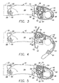
- the head portion includes a lower jaw 44 pivotally connected to a fixed upper jaw 46 by a hinge pin 48. See Figs. 3-6.
- the jaws define an opening 50 adapted to receive either a round or rectangular crossbar. It should be noted that the opening is shaped to grip the round bar as close to the hinge point as possible to thereby maximize clamping force on the round bar.
- Lower jaw 44 is selectively secured by a catch 52 controlled by a handle 54.
- Handle 54 is pivotally mounted to head portion 40 at a pivot pin 56.
- the catch includes an upper hoop 58 that fits around a pin 60 carried by handle 54.
- the catch also includes a lower hook 62 that fits into a recess 64 formed in the free end of the lower jaw.
- the catch As the handle is raised to the open position, the catch is lowered sufficiently to allow the hook to be removed from the recess, releasing the lower jaw. To secure the jaw, the hook is placed in the recess and the handle is depressed. This brings the catch up and closes the jaw. The hook has sufficient curvature to provide some tension on the lower jaw in the closed position.
- the arrangement of couplings between the handle, catch and lower jaw creates an over-center geometry when the handle is in the closed position so that the handle tends to remain closed unless manually opened.
- Head portion 40 includes a passage 70 configured to receive a skewer bolt 72.
- the skewer bolt is removable and serves to clamp the forks to the head portion.
- a locking mechanism interacts with the skewer bolt to selectively permit or prevent the opening of the lower jaw.
- the locking mechanism includes a toggle member 74 pivotally mounted on pivot pin 56.
- the toggle member includes a lever end 76 and an interference end 78 that projects through slots 80, 82 formed in the handle and catch into passage 70. See Fig. 7. Prior to installation of the skewer bolt, the lever can be pushed down to place the interference end above the skewer bolt or raised to place the interference end below the skewer bolt. Once the skewer bolt is installed, the toggle member cannot be transitioned between the upper and lower positions.
- the handle When the toggle member is in the lower or released configuration, the handle can be operated normally to clamp or release a crossbar. However, when the toggle member is in the upper or locked configuration, it blocks movement of the handle and therefore release of the crossbar. More specifically, in the locked configuration, the upper surface of the interference end rides against the lower surface of the skewer, while the lower surface is located against the bottom of slot 80. In order to rotate the handle, the bottom of the slot must rotate upward, which cannot happen while the toggle is under the skewer bolt.
- the locking mechanism By using the locking mechanism, a user can select at the time they install the skewer bolt whether or not they want the fork block to be releasable on the crossbar with the skewer locked. By engaging the locking mechanism, additional security against theft of the fork block and/or bicycle is obtained. However, by unlocking the mechanism, it is easier to adjust the location of the fork blocks on the crossbars to accommodate various bicycles or combinations of other equipment that might be mounted to the crossbars.
- Extension portion 42 is generally elongate and extends back from head portion 40 to a wheel tray mount 86.
- the wheel tray is secured to the wheel tray mount by a bolt 88 and nut 90.
- the extension portion includes a waist region 92 between the head portion and wheel tray mount to provide increased clearance for calipers 20. See Fig. 8.
- Waist region 92 includes two elongate side members 94. It should be noted that waist region 92 is narrower than the wheel tray. In fork blocks where the wheel tray mounts to the fork block adjacent the skewer, the wheel tray interferes with the calipers.
- Typical wheel trays are formed as an aluminum extrusion and have a width that is dictated by the size of bicycle tires. Therefore, the wheel trays cannot easily be resized to provide the clearance offered by extension portion 42.
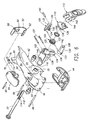
- Skewer bolt 72 forms part of a skewer assembly 100. See Fig. 6.
- skewer assembly 100 includes a housing 102, an adjustment wheel 104, a transfer link 106, a spring 108, a cam plate 110 and a cam lever 112.
- the skewer bolt has a threaded end 114 that fits through a fork-clamping end 116 of housing 102.
- the threaded end of the skewer is formed with flats 118 on each side of the threaded region.
- Wheel 104 threads onto threaded end 114 to provide adjustment of the clamping pressure spacing on the skewer.
- Wheel 104 includes a textured gripping perimeter 120 and a coupling flange 122.
- the coupling flange 122 is captured in recesses 124 formed in halves 126, 128 of transfer link 106. This arrangement allows the wheel to rotate within the link, but not move longitudinally relative to it.
- the flattened end of the skewer bolt rides in shank section 130 of the link in an elongate track 132 formed in each half of the link.
- the tracks have a flat bottom that interacts with the flats on the end of the skewer bolt to prevent the skewer bolt from rotating in the link, while still permitting the bolt to shift longitudinally for adjustment purposes.
- the link includes tabs 133 that slide in tracks 134 formed in housing 102.
- Spring 108 fits over shank section 130 and biases against the bottom of cam plate 110. This tends to push the wheel away from the cam plate and therefore biases the skewer bolt to the open position.
- the cam plate includes ribs 136 that fit in tracks 134 to prevent the cam plate from rotating in the housing.
- the cam plate is secured to the housing by a pair of lock pins 137 pressed through holes 138 in the housing and cam plate.
- Cam lever 112 is attached to the end of the shank section of transfer link 106 via a pin 140 pressed through holes 142 formed in the shank and lever.
- the cam lever includes an arcuate cam surface 144 that rides against cam plate 110.
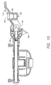
- the cam surface is shaped to shift the link toward and away from the lever end of the skewer assembly to tighten or loosen the skewer assembly. See Figs. 9 and 10.
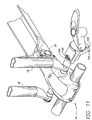
- the housing including access openings 146 that provide access to the adjustment wheel when the lever is in the released position. See Fig. 11.
- the lever when the lever is open, the user can rotate the wheel to select the correct spacing and tension to accommodate a particular set of bicycle forks.
- the wheel is retracted into the housing, preventing further adjustment. This is significant because it prevents a third party from using pliers or some other tool to loosen the skewer assembly so long as the lever remains in the closed position. So long as the toggle is placed in the locked configuration, the fork block also cannot be removed from the crossbars.
- the lever includes a lock receptacle 150 configured to receive a lock body 152.
- the lock body includes a rotatable T-catch 154 that can be rotated with a key to either pass through or catch on a slot 156 formed in a lock shelf located on the side of the housing.
- the catch is engaged to catch on the slot, the lever cannot be opened to release the skewer assembly, and, as long as the lever remains closed, the wheel is hidden and cannot be used to loosen the skewer.
- the wheel is mounted inside the housing and the skewer housing cannot rotate on the skewer bolt because of the interaction of the flats in the transfer link, it is not possible to use the skewer housing as a handle to loosen the skewer assembly.
- the various structural members of the disclosed embodiment may be constructed of steel, stainless steel, nylon, aluminum or similar materials with sufficient structural strength to withstand the loads incurred in use.
Landscapes
- Engineering & Computer Science (AREA)
- Mechanical Engineering (AREA)
- Fittings On The Vehicle Exterior For Carrying Loads, And Devices For Holding Or Mounting Articles (AREA)
- Motorcycle And Bicycle Frame (AREA)
- Traffic Control Systems (AREA)
- Devices For Conveying Motion By Means Of Endless Flexible Members (AREA)
- Developing Agents For Electrophotography (AREA)
- Valve Device For Special Equipments (AREA)
Claims (10)
- Fahrradträger mit:einer Gestellstruktur (14), die eingerichtet ist an ein Kraftfahrzeug montiert zu werden;eine langgestreckte Radablage (22) mit einem ersten Ende und einem zweiten Ende, wo die Radablage an der Gestellstruktur (14) an einem Ort befestigt ist, der von dem ersten Ende im Abstand angeordnet ist; und einem Gabelblock (16), der der Gabelstruktur zugeordnet ist und eine Spindelanordnung (100) aufweist, die eingerichtet ist, wahlweise die Gabeln (18) eines Fahrrads an dem Gabelblock (16) zu befestigen, dadurch gekennzeichnet, dass der Fahrradträger ferner einen langgestreckten Auslegerabschnitt (42) aufweist, der zwischen der Spindelanordnung (100) und einer Radablagehalterung (86) sich erstreckt, wo das erste Ende der Radablage (22) an die Radablagehalterung (86) montiert ist.
- Fahrradträger gemäß Anspruch 1, wobei die Spindelanordnung ein Gehäuse (102), einen Klemmmechanismus (106, 108, 110, 112) und ein Adjustierteil (104) aufweist, wo der Klemmmechanismus zwischen einer Offen- und einer Geschlossenkonfiguration betätigbar ist und wo das Adjustierteil (104) einem Anwender zugänglich ist in der Offenkonfiguration und einem Anwender unzugänglich ist in der Geschlossenkonfiguration.
- Fahrradträger gemäß Anspruch 1 oder Anspruch 2, wobei der Gabelblock (16) eine bewegliche Klemmbacke (44) aufweist, die schwenkbar mit einer festen Klemmbacke an einem Gelenk befestigt ist, wobei die Klemmbacken eine Öffnung zwischen ihnen definieren, die eingerichtet ist, eine Querstange (30) aufzunehmen, wo die Öffnung derart gestaltet ist, eine runde Querstange aufzunehmen und zu klemmen und auch derart gestaltet ist, eine rechteckige Querstange aufzunehmen und zu klemmen.
- Fahrradträger gemäß einem der vorhergehenden Ansprüche, wobei der Gabelblock (16) einen Verriegelungsmechanismus (74) aufweist, der adjustierbar zwischen einer ersten und einer zweiten Konfiguration ist, wo in der ersten Konfiguration der Verriegelungsmechanismus unterbindet, dass der Gabelblock von der Gestellstruktur entfernt werden kann und in der zweiten Konfiguration ermöglicht, dass der Verriegelungsmechanismus von der Gestellstruktur entfernt werden kann.
- Fahrradträger gemäß einem der vorhergehenden Ansprüche, wobei die Radablage (22) eine Breite quer zu ihrer Längsachse hat und der Auslegerabschnitt schmäler ist als die Breite der Radablage (22), um ein Spiel für die Scheibenbremssättel (20) bereitzustellen, die an den Gabeln des Fahrrads angebaut sind.
- Fahrradträger gemäß einem der vorhergehenden Ansprüche, wobei der Gabelblock (16) eine bewegliche Klemmbacke (44) aufweist, die schwenkbar mit einer festen Klemmbacke (46) an einem Gelenk verbunden ist, wobei die Klemmbacken eine Öffnung zwischen ihnen definieren, die eingerichtet ist, eine Querstange (30) aufzunehmen, und optional wobei die Öffnung derart gestaltet ist, entweder eine runde oder eine rechteckige Querstange (30) aufzunehmen und zu klemmen, wobei die Öffnung optional derart gestaltet ist, eine runde Querstange in einer Position zu halten mit dem Mittelpunkt der Querstange näher an dem Gelenk als dort, wo die Öffnung eine rechteckige Querstange hält.
- Fahrradträger gemäß Anspruch 2, wobei die Betätigung des Klemmmechanismus das Adjustierteil (104) in das Gehäuse (102) hinein und wenigstens heraus dem Gehäuse (102) verschiebt.
- Fahrradträger gemäß Anspruch 7, wobei das Adjustierteil radförmig (104) ausgebildet ist und auf einen Spindelbolzen (72) aufgefädelt ist.
- Fahrradträger gemäß Anspruch 4, wobei der Verriegelungsmechanismus (74) derart konfiguriert ist, so dass er nur zwischen der ersten Konfiguration und der zweiten Konfiguration wechselbar ist, wenn die Bolzenanordnung (100) von dem Gabelblock entfernt ist.
- Verfahren zum Bereitstellen von Spiel für Bremssättel (20) in einem Fahrradträger, wobei der Träger aufweist:einen Gabelblock (16), der an eine Gestellstruktur (14) montiert ist, wobei der Gabelblock eine Spindel (72) aufweist, die im Betrieb die Vordergabeln (18) eines Fahrrads klemmt, um das Fahrrad an die Gestellstruktur (14) zu befestigen, undeine Radablage (22), die in Richtung weg von dem Gabelblock (16) sich erstreckt, um das Hinterrad eines Fahrrads abzustützen, wobei die Radablage (22) an ihrem Ende an eine Radablagehalterung befestigt ist, das dem Gabelblock (16) näher ist,gekennzeichnet dadurch, dass das Verfahren aufweist das Bereitstellen eines Auslegerabschnitts (42) zwischen dem Gabelblock und der Radablage (22), wobei der Auslegerabschnitt (42) einen Taillenbereich (92) aufweist, der schmäler ist als die Radablage.
Applications Claiming Priority (3)
| Application Number | Priority Date | Filing Date | Title |
|---|---|---|---|
| US585723 | 2000-05-31 | ||
| US09/585,723 US6494351B1 (en) | 2000-05-31 | 2000-05-31 | Bicycle carrier |
| PCT/US2001/017585 WO2001092062A1 (en) | 2000-05-31 | 2001-05-30 | Bicycle carrier |
Publications (3)
| Publication Number | Publication Date |
|---|---|
| EP1299263A1 EP1299263A1 (de) | 2003-04-09 |
| EP1299263A4 EP1299263A4 (de) | 2004-07-21 |
| EP1299263B1 true EP1299263B1 (de) | 2006-03-01 |
Family
ID=24342679
Family Applications (1)
| Application Number | Title | Priority Date | Filing Date |
|---|---|---|---|
| EP01946020A Expired - Lifetime EP1299263B1 (de) | 2000-05-31 | 2001-05-30 | Fahrradträger |
Country Status (6)
| Country | Link |
|---|---|
| US (3) | US6494351B1 (de) |
| EP (1) | EP1299263B1 (de) |
| AT (1) | ATE318733T1 (de) |
| AU (1) | AU2001268117A1 (de) |
| DE (1) | DE60117544T2 (de) |
| WO (1) | WO2001092062A1 (de) |
Cited By (3)
| Publication number | Priority date | Publication date | Assignee | Title |
|---|---|---|---|---|
| US8505793B2 (en) | 2005-08-09 | 2013-08-13 | Yakima Innovation Development Corporation | Bicycle carrier |
| US10300865B2 (en) | 2016-06-05 | 2019-05-28 | Yakima Products, Inc. | Fork-mount bicycle carrier |
| US10857949B2 (en) | 2017-04-18 | 2020-12-08 | Yakima Products, Inc. | Fork mount bicycle carrier |
Families Citing this family (50)
| Publication number | Priority date | Publication date | Assignee | Title |
|---|---|---|---|---|
| US6283310B1 (en) * | 1999-11-23 | 2001-09-04 | Yakima Products, Inc. | Bicycle carrier |
| US6494351B1 (en) * | 2000-05-31 | 2002-12-17 | Yakima Products, Inc. | Bicycle carrier |
| US6758380B1 (en) | 2002-04-09 | 2004-07-06 | Graber Products, Inc. | Locking fork mount for a bicycle carrier |
| US6767157B2 (en) * | 2002-09-26 | 2004-07-27 | International Business Machines Corporation | Toolless fastening mechanism |
| US20050082324A1 (en) * | 2003-10-20 | 2005-04-21 | Schlachter Bradley S. | Article carrier and bicycle rack system |
| US7757917B2 (en) * | 2004-11-01 | 2010-07-20 | Thule Sweden Ab | Anti-sway arrangement for cargo on a load carrier |
| US20070012738A1 (en) * | 2005-07-12 | 2007-01-18 | Michael Grim | Through-axle bicycle fork mounting clamp |
| US7726528B2 (en) * | 2005-08-09 | 2010-06-01 | Yakima Products, Inc. | Bicycle carrier |
| US20070034658A1 (en) * | 2005-08-10 | 2007-02-15 | Terry N. Clark | Vehicle accessory rack |
| USD562218S1 (en) | 2006-03-23 | 2008-02-19 | Yakima Products, Inc. | Fork mount bicycle carrier |
| USD561680S1 (en) | 2006-03-23 | 2008-02-12 | Yakima Products, Inc. | Fork mount bicycle carrier |
| GB0607064D0 (en) * | 2006-04-07 | 2006-05-17 | Nissan Technical Ct Europ Ltd | Improvements relating to vehicles and vehicle features |
| TWM303854U (en) * | 2006-06-29 | 2007-01-01 | Chiou-Guei Wang | Structure serving as roof rack and bicycle rack |
| US20080061198A1 (en) * | 2006-09-08 | 2008-03-13 | Rocky Mounts | Carrier and Adaptor for Transporting a Bicycle on a Fork Mount Holding/Transporting System |
| NZ561811A (en) | 2007-09-21 | 2010-06-25 | Hubco Automotive Ltd | Extendable roof rack |
| US8281625B2 (en) | 2008-07-28 | 2012-10-09 | Thule Sweden Ab | Locking skewer for securing bikes to a rack |
| US20100059563A1 (en) * | 2008-09-11 | 2010-03-11 | Hannum Alan H | Bicycle rack for motorcycles |
| TW201111201A (en) | 2009-06-05 | 2011-04-01 | Yakima Products Inc | Upright bike mount |
| WO2010144749A1 (en) * | 2009-06-12 | 2010-12-16 | Yakima Products, Inc. | Skewer assembly for bicycle fork mount |
| TWI594906B (zh) * | 2009-06-15 | 2017-08-11 | 亞奇瑪產品公司 | 橫桿夾持裝置 |
| WO2012018693A1 (en) * | 2010-08-01 | 2012-02-09 | Thule Sweden Ab | Carrier mount, locking mechanism therefore and corresponding assembling method |
| US8915411B2 (en) * | 2011-02-15 | 2014-12-23 | Eric Samuel Steckel | Utility slidable rack-rail system |
| USD653193S1 (en) * | 2011-05-23 | 2012-01-31 | Philip Patrick Chisholm | Roof rack bicycle fork adapter |
| BR122015018573A2 (pt) * | 2011-08-05 | 2019-08-27 | Cequent Performance Prod Inc | mecanismo de dobramento para um acessório de carga |
| WO2013022749A1 (en) | 2011-08-05 | 2013-02-14 | Cequent Performance Products, Inc. | Cargo accessory modular adapter |
| US9931993B2 (en) * | 2011-08-05 | 2018-04-03 | Horizon Global Americas Inc. | Accessory adapter bracket |
| US9187047B2 (en) | 2012-04-30 | 2015-11-17 | Yakima Products, Inc. | Retention dock |
| US9283884B2 (en) | 2012-04-30 | 2016-03-15 | Yakima Produtcs, Inc. | Attachment devices for vehicle rooftop rack accessories |
| USD689012S1 (en) * | 2013-01-18 | 2013-09-03 | Luke Kuschmeader | Bicycle fork mount |
| US20140367431A1 (en) * | 2013-06-14 | 2014-12-18 | Keith Sutter | Bicycle carrier apparatus |
| EP3060432B1 (de) * | 2013-07-26 | 2017-08-30 | Thule Sweden AB | Anker oder lastträger für eine fahrraddurchgangsachse |
| US9517729B2 (en) * | 2013-10-16 | 2016-12-13 | Girak Llc | Adjustable and/or repositionable bicycle mount |
| US20150151687A1 (en) * | 2013-12-03 | 2015-06-04 | King Shen Co., Ltd. | Apparatus for holding a fork of a mountain bicycle |
| US9873385B2 (en) | 2013-12-03 | 2018-01-23 | King Shen Co., Ltd. | Bicycle mounting adapter |
| WO2015106040A1 (en) | 2014-01-08 | 2015-07-16 | Yakima Innovation Development Corporation | Board carrier |
| GB201402811D0 (en) * | 2014-02-18 | 2014-04-02 | C P Witter Ltd | Support bars and cycle carriers |
| US20160131166A1 (en) * | 2014-04-10 | 2016-05-12 | Brian Cox | Bicycle Mount |
| USD759571S1 (en) * | 2014-08-05 | 2016-06-21 | Thule Sweden Ab | Fork mount bicycle carrier |
| US9457630B2 (en) * | 2014-12-05 | 2016-10-04 | Ford Global Technologies, Llc | Towing device |
| USD814388S1 (en) * | 2015-05-15 | 2018-04-03 | F.Lli Menabo′ S.R.L. | Bicycle carrier |
| US10040403B2 (en) | 2015-06-09 | 2018-08-07 | Yakima Products, Inc. | Crossbar clamp actuator |
| US9738231B2 (en) * | 2015-07-24 | 2017-08-22 | Thule Sweden Ab | Bicycle carriers and skewer assemblies |
| US9862330B2 (en) | 2015-08-03 | 2018-01-09 | Jeffrey Dennis Sayegh | Rack for pickup trucks and trailers |
| CN109641558B (zh) | 2016-06-05 | 2022-09-16 | 雅捷马产品公司 | 直立自行车承载架 |
| US10543771B2 (en) | 2016-06-05 | 2020-01-28 | Yakima Products, Inc. | Vehicle rooftop rack assembly |
| USD855009S1 (en) * | 2017-07-20 | 2019-07-30 | Glox Co., Ltd. | Bicycle carrier for vehicles |
| TWI670190B (zh) * | 2018-10-18 | 2019-09-01 | 錦聖科技股份有限公司 | 可調整安裝規格之前叉安裝座 |
| EP3838678B1 (de) * | 2019-12-20 | 2022-04-27 | Thule Sweden AB | Trageinheit für einen fahrradträger |
| US12179711B2 (en) * | 2023-04-13 | 2024-12-31 | Joel W Miller | Locking release lever for securing a bicycle on a bicycle rack |
| DE102023122845A1 (de) * | 2023-08-25 | 2025-02-27 | BOS Technology Services GmbH | Befestigungssystem zur Befestigung eines Fahrrads an einem Fahrradträger |
Family Cites Families (27)
| Publication number | Priority date | Publication date | Assignee | Title |
|---|---|---|---|---|
| JPS5131579B1 (de) | 1971-06-26 | 1976-09-07 | ||
| US3828993A (en) | 1972-01-20 | 1974-08-13 | J Carter | Bicycle transporting rack |
| FR2251187A5 (en) * | 1973-11-08 | 1975-06-06 | Canetti Et Cie J E | Automobile roof rack for carrying a bicycle - supports front wheel separately at the side |
| FR2420454A1 (fr) * | 1978-03-20 | 1979-10-19 | Saint Julien Chaudronnerie | Porte-bicyclette adaptable sur un porte-bagage de vehicule |
| FR2428545A1 (fr) * | 1978-06-13 | 1980-01-11 | Rolland Raymond | Porte-bicyclette destine au transport d'une bicyclette sur le porte-bagages d'un vehicule automobile |
| FR2551705A1 (fr) * | 1983-09-12 | 1985-03-15 | Macorex Exploit Ets | Porte-bicyclette destine a equiper les barres porte-bagages d'un vehicule automobile |
| SE458847B (sv) * | 1987-09-02 | 1989-05-16 | J S Products Ab | Anordning vid fordonsuppburen lastbaerare foer cykel |
| US4842148A (en) | 1988-02-23 | 1989-06-27 | Bowman Tracy L | Quick release bicycle rack |
| SE461902B (sv) * | 1988-04-20 | 1990-04-09 | J S Products Ab | Anordning foer montering av cykel etc till ett fordons lastbaerare |
| SE461779B (sv) | 1988-09-13 | 1990-03-26 | Thule Ind Ab | Cyckelhaallare |
| US5275319A (en) * | 1990-03-29 | 1994-01-04 | Bruce Ruana | Bicycle rack wind deflector |
| US5362173A (en) | 1992-09-17 | 1994-11-08 | Industri Ab Thule | Lockable quick release mechanism |
| DE4315024A1 (de) | 1993-05-06 | 1994-11-10 | Happich Gmbh Gebr | Dachgepäckträger für Kraftfahrzeuge mit Dachreling |
| US5377886A (en) * | 1993-07-01 | 1995-01-03 | Sickler; John R. | Modular bicycle rack for motor vehicles |
| SE502961C2 (sv) | 1993-09-07 | 1996-03-04 | Thule Ind Ab | Cykelhållare |
| DE4334331A1 (de) | 1993-10-08 | 1995-04-13 | Happich Gmbh Gebr | Querträger für Dachlasten an einem mit einer Dachreling ausgestatteten Kraftwagen |
| US5598959A (en) | 1995-07-06 | 1997-02-04 | Yakima Products | Article-carrying rack with lockable mount |
| GB2303344A (en) * | 1995-07-20 | 1997-02-19 | Keith White | Vehicle roof rack |
| US5730343A (en) * | 1996-01-12 | 1998-03-24 | Settelmayer; Joseph J. | Tower assembly for mounting a crossbar to a vehicle roof rack |
| CA2186814A1 (en) * | 1996-03-01 | 1997-09-02 | Bell Sportrack, Division Of Bell Sports Canada Inc. | Universal load-carrying utility rack for vehicles |
| SE507371C2 (sv) | 1996-09-10 | 1998-05-18 | Thule Ind Ab | Relinghållare |
| US5875947A (en) | 1996-10-21 | 1999-03-02 | Industri Ab Thule | Centralized handled bicycle fork anchor |
| US5924614A (en) * | 1997-04-03 | 1999-07-20 | Decoma International Inc. | Article carrier assembly having a cross rail assembly longitudinally adjustable from one side of a motor vehicle |
| TW392631U (en) * | 1999-01-29 | 2000-06-01 | Errow Drew | Improved structure for bicycle retaining rack |
| US6283310B1 (en) * | 1999-11-23 | 2001-09-04 | Yakima Products, Inc. | Bicycle carrier |
| US6425509B1 (en) * | 1999-11-23 | 2002-07-30 | Yakima Products, Inc. | Bicycle carrier |
| US6494351B1 (en) * | 2000-05-31 | 2002-12-17 | Yakima Products, Inc. | Bicycle carrier |
-
2000
- 2000-05-31 US US09/585,723 patent/US6494351B1/en not_active Expired - Fee Related
-
2001
- 2001-05-30 WO PCT/US2001/017585 patent/WO2001092062A1/en not_active Ceased
- 2001-05-30 EP EP01946020A patent/EP1299263B1/de not_active Expired - Lifetime
- 2001-05-30 DE DE60117544T patent/DE60117544T2/de not_active Expired - Lifetime
- 2001-05-30 AT AT01946020T patent/ATE318733T1/de not_active IP Right Cessation
- 2001-05-30 AU AU2001268117A patent/AU2001268117A1/en not_active Abandoned
-
2002
- 2002-12-16 US US10/321,299 patent/US6851590B2/en not_active Expired - Fee Related
-
2005
- 2005-02-07 US US11/053,180 patent/US7237704B2/en not_active Expired - Fee Related
Cited By (4)
| Publication number | Priority date | Publication date | Assignee | Title |
|---|---|---|---|---|
| US8505793B2 (en) | 2005-08-09 | 2013-08-13 | Yakima Innovation Development Corporation | Bicycle carrier |
| US10300865B2 (en) | 2016-06-05 | 2019-05-28 | Yakima Products, Inc. | Fork-mount bicycle carrier |
| US10857949B2 (en) | 2017-04-18 | 2020-12-08 | Yakima Products, Inc. | Fork mount bicycle carrier |
| US11858471B2 (en) | 2017-04-18 | 2024-01-02 | Yakima Products, Inc. | Fork mount bicycle carrier |
Also Published As
| Publication number | Publication date |
|---|---|
| EP1299263A1 (de) | 2003-04-09 |
| DE60117544T2 (de) | 2006-12-28 |
| AU2001268117A1 (en) | 2001-12-11 |
| US20050205627A1 (en) | 2005-09-22 |
| US6494351B1 (en) | 2002-12-17 |
| US6851590B2 (en) | 2005-02-08 |
| ATE318733T1 (de) | 2006-03-15 |
| EP1299263A4 (de) | 2004-07-21 |
| WO2001092062A1 (en) | 2001-12-06 |
| US20030146257A1 (en) | 2003-08-07 |
| DE60117544D1 (de) | 2006-04-27 |
| US7237704B2 (en) | 2007-07-03 |
Similar Documents
| Publication | Publication Date | Title |
|---|---|---|
| EP1299263B1 (de) | Fahrradträger | |
| US6460708B2 (en) | Bicycle carrier | |
| US6425509B1 (en) | Bicycle carrier | |
| AU2009262300B2 (en) | Bicycle carrier with fork mount and universal crossbar clamp | |
| US6761297B1 (en) | Ride ready vehicle-mounted bicycle carrier | |
| US8505793B2 (en) | Bicycle carrier | |
| US7726528B2 (en) | Bicycle carrier | |
| US8496145B2 (en) | Vehicle rack for carrying a wheel | |
| US5845828A (en) | Tower assembly for mounting a crossbar to a vehicle roof rack | |
| EP2443006B1 (de) | Klemmvorrichtungen mit querverstrebung | |
| WO2001038141A1 (en) | Rack assembly for a vehicle | |
| WO2013166048A1 (en) | Attachment devices for vehicle rooftop rack accessories | |
| US9950675B2 (en) | Modular roof rack clamping system | |
| US6905053B2 (en) | Rack tower | |
| WO2017214066A1 (en) | Fork-mount bicycle carrier | |
| MXPA97003844A (en) | Porta-articular frame with divided mount that has a pivote knob | |
| WO2003059692A1 (en) | Rack tower | |
| NZ533803A (en) | Device to clamp to tow ball of vehicle with cantilevered supports pivotable from respective uprights |
Legal Events
| Date | Code | Title | Description |
|---|---|---|---|
| PUAI | Public reference made under article 153(3) epc to a published international application that has entered the european phase |
Free format text: ORIGINAL CODE: 0009012 |
|
| 17P | Request for examination filed |
Effective date: 20021223 |
|
| AK | Designated contracting states |
Kind code of ref document: A1 Designated state(s): AT BE CH CY DE DK ES FI FR GB GR IE IT LI LU MC NL PT SE TR |
|
| AX | Request for extension of the european patent |
Extension state: AL LT LV MK RO SI |
|
| A4 | Supplementary search report drawn up and despatched |
Effective date: 20040608 |
|
| 17Q | First examination report despatched |
Effective date: 20050216 |
|
| GRAP | Despatch of communication of intention to grant a patent |
Free format text: ORIGINAL CODE: EPIDOSNIGR1 |
|
| GRAS | Grant fee paid |
Free format text: ORIGINAL CODE: EPIDOSNIGR3 |
|
| GRAA | (expected) grant |
Free format text: ORIGINAL CODE: 0009210 |
|
| AK | Designated contracting states |
Kind code of ref document: B1 Designated state(s): AT BE CH CY DE DK ES FI FR GB GR IE IT LI LU MC NL PT SE TR |
|
| PG25 | Lapsed in a contracting state [announced via postgrant information from national office to epo] |
Ref country code: AT Free format text: LAPSE BECAUSE OF FAILURE TO SUBMIT A TRANSLATION OF THE DESCRIPTION OR TO PAY THE FEE WITHIN THE PRESCRIBED TIME-LIMIT Effective date: 20060301 Ref country code: LI Free format text: LAPSE BECAUSE OF FAILURE TO SUBMIT A TRANSLATION OF THE DESCRIPTION OR TO PAY THE FEE WITHIN THE PRESCRIBED TIME-LIMIT Effective date: 20060301 Ref country code: FI Free format text: LAPSE BECAUSE OF FAILURE TO SUBMIT A TRANSLATION OF THE DESCRIPTION OR TO PAY THE FEE WITHIN THE PRESCRIBED TIME-LIMIT Effective date: 20060301 Ref country code: CH Free format text: LAPSE BECAUSE OF FAILURE TO SUBMIT A TRANSLATION OF THE DESCRIPTION OR TO PAY THE FEE WITHIN THE PRESCRIBED TIME-LIMIT Effective date: 20060301 Ref country code: NL Free format text: LAPSE BECAUSE OF FAILURE TO SUBMIT A TRANSLATION OF THE DESCRIPTION OR TO PAY THE FEE WITHIN THE PRESCRIBED TIME-LIMIT Effective date: 20060301 Ref country code: BE Free format text: LAPSE BECAUSE OF FAILURE TO SUBMIT A TRANSLATION OF THE DESCRIPTION OR TO PAY THE FEE WITHIN THE PRESCRIBED TIME-LIMIT Effective date: 20060301 |
|
| REG | Reference to a national code |
Ref country code: GB Ref legal event code: FG4D |
|
| REG | Reference to a national code |
Ref country code: CH Ref legal event code: EP |
|
| REG | Reference to a national code |
Ref country code: IE Ref legal event code: FG4D |
|
| REF | Corresponds to: |
Ref document number: 60117544 Country of ref document: DE Date of ref document: 20060427 Kind code of ref document: P |
|
| PG25 | Lapsed in a contracting state [announced via postgrant information from national office to epo] |
Ref country code: IE Free format text: LAPSE BECAUSE OF NON-PAYMENT OF DUE FEES Effective date: 20060530 |
|
| PG25 | Lapsed in a contracting state [announced via postgrant information from national office to epo] |
Ref country code: MC Free format text: LAPSE BECAUSE OF NON-PAYMENT OF DUE FEES Effective date: 20060531 |
|
| PG25 | Lapsed in a contracting state [announced via postgrant information from national office to epo] |
Ref country code: SE Free format text: LAPSE BECAUSE OF FAILURE TO SUBMIT A TRANSLATION OF THE DESCRIPTION OR TO PAY THE FEE WITHIN THE PRESCRIBED TIME-LIMIT Effective date: 20060601 Ref country code: DK Free format text: LAPSE BECAUSE OF FAILURE TO SUBMIT A TRANSLATION OF THE DESCRIPTION OR TO PAY THE FEE WITHIN THE PRESCRIBED TIME-LIMIT Effective date: 20060601 |
|
| PG25 | Lapsed in a contracting state [announced via postgrant information from national office to epo] |
Ref country code: ES Free format text: LAPSE BECAUSE OF FAILURE TO SUBMIT A TRANSLATION OF THE DESCRIPTION OR TO PAY THE FEE WITHIN THE PRESCRIBED TIME-LIMIT Effective date: 20060612 |
|
| PG25 | Lapsed in a contracting state [announced via postgrant information from national office to epo] |
Ref country code: PT Free format text: LAPSE BECAUSE OF FAILURE TO SUBMIT A TRANSLATION OF THE DESCRIPTION OR TO PAY THE FEE WITHIN THE PRESCRIBED TIME-LIMIT Effective date: 20060801 |
|
| NLV1 | Nl: lapsed or annulled due to failure to fulfill the requirements of art. 29p and 29m of the patents act | ||
| REG | Reference to a national code |
Ref country code: CH Ref legal event code: PL |
|
| ET | Fr: translation filed | ||
| PLBE | No opposition filed within time limit |
Free format text: ORIGINAL CODE: 0009261 |
|
| STAA | Information on the status of an ep patent application or granted ep patent |
Free format text: STATUS: NO OPPOSITION FILED WITHIN TIME LIMIT |
|
| 26N | No opposition filed |
Effective date: 20061204 |
|
| PG25 | Lapsed in a contracting state [announced via postgrant information from national office to epo] |
Ref country code: GR Free format text: LAPSE BECAUSE OF FAILURE TO SUBMIT A TRANSLATION OF THE DESCRIPTION OR TO PAY THE FEE WITHIN THE PRESCRIBED TIME-LIMIT Effective date: 20060602 |
|
| PG25 | Lapsed in a contracting state [announced via postgrant information from national office to epo] |
Ref country code: LU Free format text: LAPSE BECAUSE OF NON-PAYMENT OF DUE FEES Effective date: 20060530 Ref country code: TR Free format text: LAPSE BECAUSE OF FAILURE TO SUBMIT A TRANSLATION OF THE DESCRIPTION OR TO PAY THE FEE WITHIN THE PRESCRIBED TIME-LIMIT Effective date: 20060301 |
|
| PG25 | Lapsed in a contracting state [announced via postgrant information from national office to epo] |
Ref country code: CY Free format text: LAPSE BECAUSE OF FAILURE TO SUBMIT A TRANSLATION OF THE DESCRIPTION OR TO PAY THE FEE WITHIN THE PRESCRIBED TIME-LIMIT Effective date: 20060301 |
|
| PG25 | Lapsed in a contracting state [announced via postgrant information from national office to epo] |
Ref country code: IT Free format text: LAPSE BECAUSE OF NON-PAYMENT OF DUE FEES Effective date: 20100530 |
|
| PGRI | Patent reinstated in contracting state [announced from national office to epo] |
Ref country code: IT Effective date: 20110616 |
|
| PGFP | Annual fee paid to national office [announced via postgrant information from national office to epo] |
Ref country code: DE Payment date: 20130529 Year of fee payment: 13 Ref country code: GB Payment date: 20130528 Year of fee payment: 13 |
|
| PGFP | Annual fee paid to national office [announced via postgrant information from national office to epo] |
Ref country code: FR Payment date: 20130618 Year of fee payment: 13 Ref country code: IT Payment date: 20130529 Year of fee payment: 13 |
|
| REG | Reference to a national code |
Ref country code: DE Ref legal event code: R119 Ref document number: 60117544 Country of ref document: DE |
|
| GBPC | Gb: european patent ceased through non-payment of renewal fee |
Effective date: 20140530 |
|
| REG | Reference to a national code |
Ref country code: FR Ref legal event code: ST Effective date: 20150130 |
|
| REG | Reference to a national code |
Ref country code: DE Ref legal event code: R119 Ref document number: 60117544 Country of ref document: DE Effective date: 20141202 |
|
| PG25 | Lapsed in a contracting state [announced via postgrant information from national office to epo] |
Ref country code: DE Free format text: LAPSE BECAUSE OF NON-PAYMENT OF DUE FEES Effective date: 20141202 Ref country code: IT Free format text: LAPSE BECAUSE OF NON-PAYMENT OF DUE FEES Effective date: 20140530 |
|
| PG25 | Lapsed in a contracting state [announced via postgrant information from national office to epo] |
Ref country code: GB Free format text: LAPSE BECAUSE OF NON-PAYMENT OF DUE FEES Effective date: 20140530 Ref country code: FR Free format text: LAPSE BECAUSE OF NON-PAYMENT OF DUE FEES Effective date: 20140602 |