EP1299642B1 - HYDRAULISCHE STRöMUNGSMASCHINE - Google Patents
HYDRAULISCHE STRöMUNGSMASCHINE Download PDFInfo
- Publication number
- EP1299642B1 EP1299642B1 EP01967133A EP01967133A EP1299642B1 EP 1299642 B1 EP1299642 B1 EP 1299642B1 EP 01967133 A EP01967133 A EP 01967133A EP 01967133 A EP01967133 A EP 01967133A EP 1299642 B1 EP1299642 B1 EP 1299642B1
- Authority
- EP
- European Patent Office
- Prior art keywords
- energy
- water
- guide
- generator
- chamber
- Prior art date
- Legal status (The legal status is an assumption and is not a legal conclusion. Google has not performed a legal analysis and makes no representation as to the accuracy of the status listed.)
- Expired - Lifetime
Links
- XLYOFNOQVPJJNP-UHFFFAOYSA-N water Substances O XLYOFNOQVPJJNP-UHFFFAOYSA-N 0.000 claims abstract description 90
- 230000001133 acceleration Effects 0.000 claims description 13
- 230000001105 regulatory effect Effects 0.000 claims 1
- 239000012530 fluid Substances 0.000 description 8
- 239000007788 liquid Substances 0.000 description 7
- 238000000034 method Methods 0.000 description 4
- 238000006243 chemical reaction Methods 0.000 description 3
- 238000001514 detection method Methods 0.000 description 3
- 230000033001 locomotion Effects 0.000 description 3
- 230000005540 biological transmission Effects 0.000 description 2
- 238000012423 maintenance Methods 0.000 description 2
- 230000007704 transition Effects 0.000 description 2
- 230000008878 coupling Effects 0.000 description 1
- 238000010168 coupling process Methods 0.000 description 1
- 238000005859 coupling reaction Methods 0.000 description 1
- 230000005611 electricity Effects 0.000 description 1
- 238000004146 energy storage Methods 0.000 description 1
- 238000005457 optimization Methods 0.000 description 1
- 230000035515 penetration Effects 0.000 description 1
- 230000002093 peripheral effect Effects 0.000 description 1
- 238000010248 power generation Methods 0.000 description 1
- 230000000630 rising effect Effects 0.000 description 1
- 230000001932 seasonal effect Effects 0.000 description 1
- 230000001960 triggered effect Effects 0.000 description 1
- 239000002699 waste material Substances 0.000 description 1
- 239000003643 water by type Substances 0.000 description 1
Images


Classifications
-
- F—MECHANICAL ENGINEERING; LIGHTING; HEATING; WEAPONS; BLASTING
- F03—MACHINES OR ENGINES FOR LIQUIDS; WIND, SPRING, OR WEIGHT MOTORS; PRODUCING MECHANICAL POWER OR A REACTIVE PROPULSIVE THRUST, NOT OTHERWISE PROVIDED FOR
- F03B—MACHINES OR ENGINES FOR LIQUIDS
- F03B17/00—Other machines or engines
- F03B17/005—Installations wherein the liquid circulates in a closed loop ; Alleged perpetua mobilia of this or similar kind
-
- F—MECHANICAL ENGINEERING; LIGHTING; HEATING; WEAPONS; BLASTING
- F05—INDEXING SCHEMES RELATING TO ENGINES OR PUMPS IN VARIOUS SUBCLASSES OF CLASSES F01-F04
- F05B—INDEXING SCHEME RELATING TO WIND, SPRING, WEIGHT, INERTIA OR LIKE MOTORS, TO MACHINES OR ENGINES FOR LIQUIDS COVERED BY SUBCLASSES F03B, F03D AND F03G
- F05B2200/00—Mathematical features
- F05B2200/10—Basic functions
- F05B2200/11—Sum
Definitions
- the invention relates to a hydraulic flow machine for Energy conversion for the energy supply of energy consumers of any kind.
- the drive power of a pump is needed to set the impeller in rotation, the atmospheric Air pressure the water column in the suction pipe and from there into the impeller suppressed.
- the water from the flow direction in the suction pipe in the direction of flow in the impeller are deflected.
- the Torque on the impeller and the centrifugal force must be the water within the blade channels of the impeller from that in the center of the Impeller existing smaller rotational speed on the am Outer diameter required circulation and exit velocity accelerated and transported.
- the required Acceleration forces must be provided by the drive of the pump Will be provided.
- the water is going out the spiral housing into a discharge nozzle, in which it on his Drive power of the impeller from the delivery and the Delivery volume of the water / per unit time and of the Energy losses determined.
- An essential feature of conventional centrifugal pump is that for in the impeller inflowing flow, the drive power of the engine is not in Claimed.
- the drive motor accelerates this into the Impeller inflowing water on the exit velocity of the the impeller flowing water. Due to the centrifugal force of the impeller circulating water creates a negative pressure compared to the pressure of prevails at the suction tube entrance.
- the resulting overpressure on the Intake manifold inlet lets the water rise in the intake manifold and into the Impeller flow. Part of the total head of the centrifugal pump However, not from the performance of the drive motor, but from the Overpressure on the intake manifold.
- the influence of the supplied flow energy on the impeller blades causes a torque on the turbine shaft. This is the working capacity of a water flow driving the turbine wheel.
- the described hydropower plants are localized and require considerable investment costs. Due to the seasonal water supply of different sizes, the available amount of water can fluctuate very strongly, which in turn has a great influence on the amount of energy available or to be dispensed to the consumer.
- EP 0 545 280 A1 also discloses a drive device with a turbine fixedly arranged on a rotatable shaft, which can be acted upon by a liquid, in particular water, and set into rotary motion together with the shaft, characterized in that the shaft is vertical is arranged that on the shaft this concentrically surrounding a conically upwardly flared tube is fixed and which has an overflow in the upper edge with an underneath, fixed collecting container for overflowing liquid, and that the turbine via at least one outgoing from the collecting container Downpipe is acted upon from below with the liquid.
- DE 196 47 476 A1 discloses a pneumatic hydraulic centrifugal drive for all types of energy movement and power generation, characterized in that record by a rotor with one or more integrated chambers / tanks water, oil or other liquids and centrifuged by acceleration / compacted and in a pressurized housing presses, wherein the housing in which the rotor is driven is under atmospheric pressure or gas pressure and filled with water or other liquids.
- the chambers of the rotor are filled via the rotor axis with liquid and thrown by the rotational movement of the rotor to the outside, whereby centrifugal forces arise, which throw the water through the arranged on the chambers nozzles from the rotor in the pressurized housing, at the bottom itself collects the water and a turbine is supplied, which returns the water to a power generator and at the same time in the rotor axis.
- the above-described solutions are based on the basic principle of buoyancy of a water column in the center about a rotating axis, from where the liquid is guided radially in a turbine wheel and forced by centrifugal forces to the outside, the disadvantages described above occur.
- the hydraulic turbomachine described in WO 00/29747 can not eliminate these disadvantages, since in this solution, the water is not supplied to the suction chamber with a trough-shaped guide, the centrifugal force does not form a balance of forces with the atmospheric pressure at the exit of the hub and the engine Water in the hub must accelerate to exit velocity.
- the invention is therefore an object of the invention to provide a hydraulic fluid flow machine that uses only due to the atmospheric air pressure acceleration of the flow circuit of a rising in a suction chamber to an impeller water column and provides as final energy to a consumer.
- the object is achieved by a hydraulic turbomachine with the characterizing features of claim 1.
- the trough-shaped flow space according to the invention of the hydraulic fluid machine inside a closed container which at the same time contains the water supply required for the function of the machine has the great advantage, in contrast to previous solutions, that only the pressure energy of the atmospheric air pressure, reduced by all losses, is delivered as final energy to a consumer.
- can act through an opening between the two inner guide walls in front of the inlet of the suction chamber within the trough-shaped flow space of the atmospheric pressure on the water level and arranged between the flow space and container compensating pipe allows the adjustability of the water level in the trough-shaped flow space.
- the height of the water level in the container by known methods such as manually through a window or appropriately arranged float or sensors that trigger a signal upon reaching a determinable level and optimally determined by a the application conditions adapted water inlet and outlet system.
- the atmospheric air pressure exerts a pressure on the water level in the trough-shaped flow space and causes, due to the force balance generated by the impeller, the water is accelerated in the suction chamber, via the guide vanes in the horizontally about the axis of the generator rotating impeller and from this is passed into the Leitraum, where it can be deflected and fed back to the suction chamber.
- the speed energy of the exit velocity of the water from the impeller adds to the pressure energy of the atmospheric Lucasrucks and by cross-sectional constriction in the vane area, the water is accelerated again to the required inlet velocity into the impeller.
- the drive motor, the impeller in a certain speed which exceeds the speed of rotation of the Water in the impeller generated centrifugal force at the outlet openings of the Impeller generates a pressure that the back pressure to the Outlets corresponds and this is directed against, whereby an equilibrium of forces arises at the impeller outlet.
- the structural design of the trough-shaped flow space coaxial about the axis of the Generator in a container with a required water supply is arranged.
- the outer guide wall of the trough-shaped Flow space forms together with two inner guide walls a suction chamber and a Leitraum, between which on the axis of the generator and horizontally rotating about this axis Impeller is guided with impeller blades, taking all components together form the annular water cycle.
- a second variant of the hydraulic according to the invention Turbomachine provides that at one, by a desired lower flow velocity in the guide and suction chamber conditional, reduced exit velocity of the water from the Impeller in place of the vanes one with the impeller horizontally around the Axis of the generator rotating accelerating wheel is provided which the missing speed energy for the Entry speed of water into the impeller with the Drive motor compensates and the ingress of atmospheric air prevented in the suction chamber.
- the amount of energy to be delivered is the inventive hydraulic turbomachine of the constructive sizes of individual components and by measuring the drive power for the energy supply in the start phase of the plant and to compensate for the determined conditional losses, the yield of final energy in the hydraulic turbomachine with guide vanes is greater than when using the accelerator, because by the accelerator additional energy losses are recorded.
- the advantages of the hydraulic turbomachine according to the invention exist, due to the structural design and the so guaranteed optimization of space requirements in the absolute Adaptability to local conditions and Performance requirements, associated low investment and Maintenance costs and a long service life.
- the machine works absolutely independent of day or seasons, allows one Cost-effective energy storage, is through the use of the atmospheric pressure as secondary energy absolute environmentally friendly and produces no waste. It does not need any Water gradient, no natural and / or jammed water source and is thus not localized.
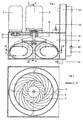
- Fig.1 and Fig.3 show an embodiment of the invention Hydraulic fluid machine with vanes 2, which with a annular water circuit according to the invention with a radial, to a Axle 6 'of a generator 6, extending flow direction is equipped.
- the annular water circuit consists of the suction chamber 1 with Suction chamber inlet 1 'and suction chamber outlet 1 ", in the area of Saugraumausgangs 1 "arranged vanes 2, the impeller 3 with Impeller blades 3 ', arranged on the inner diameter D1 Inlet openings 3 "and arranged on the outer diameter D2 Outlet openings 3 '”and a Leitraum 7 with inlet opening 7' and Outlet opening 7 ", within a trough-shaped Flow space 8 coaxially about the axis 6 'of the generator 6 in one Container 9 is arranged, wherein the impeller 3 between the suction chamber 1 and the Leitraum 7 horizontally to the axis 6 'rotates and the transition from the guide vanes 2 to the impeller 3 preferably by a non-contact seal 24 is sealed according to Figure 4.
- the trough-shaped flow space 8 consists of a, in a container. 9 arranged non-positively, outer guide wall 8 ', with a inner guide wall 8 "forms the suction chamber 1 and over in the Suction chamber 1 arranged vanes 2 with the outer Guide wall 8 'is connected and with an inner guide wall 8 "'forms the Leitraum 7 and guide webs 17 with the outer Guide wall 8 'is connected. Between the two inner ones Guide walls 8 "and 8 '" is in the inner bottom area of the trough-shaped flow space 8 an opening arranged. Furthermore is located in this floor area, a water level 4 ', the for example, via a compensating pipe 10 to the container 9 is adjustable.
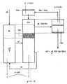
- the container 9 is preferably with two container chambers 12 and 13 equipped.
- the container 9 When starting the machine is from the For example, higher arranged container chamber 13 preferably via a directional control valve 14, water 4 filled in the container 9, whereby the Air from the suction chamber 1 and the Leitraum 7 and from the impeller. 3 is displaced. After reaching the required speed or after Completion of the startup process is now in the container 9 excess Water 4 via the preferably second directional control valve 14 in the Container chamber 12 passed.
- the water level is too low 4 'in the Container 9 or in the flow chamber 8 is 4 of the water Container chamber 12 via, for example, a check valve 15 and a Pump 16 pumped into the container chamber 13 and from there via the first Directional valve 14 back to the container 9 back to the water level 4 'back to the level required for the function of the machine was reduced.
- a check valve 15 and a Pump 16 pumped into the container chamber 13 and from there via the first Directional valve 14 back to the container 9 back to the water level 4 'back to the level required for the function of the machine was reduced.
- For the detection and regulation of the water level 4 ' in the container 9 conventionally known methods are provided as the manual detection through a viewing window and its manual Regulation or detection via a float or sensor and by these triggered electrical signals to the directional control valves 14.
- the Generator 6 is arranged outside of the container 9 so that he for example via a coupling 22 and a bearing 23 with the axis 6 ' is connected, wherein on the, in the container 9 vertically protruding Axial part as a transmission element 20, 21 preferably one Pulley 20 is arranged via a belt 21 with a second pulley 20 on the axis of the also outside the Container 9 arranged drive motor 5 are interconnected.
- the impeller 3 is arranged on another bearing 23 so that it can rotate horizontally about the axis 6 '.
- the axis 6 'of the flow space 8 is arranged, in which the circular Water circulation is installed, whereby the the floor area of the Flow space 8 opposite opening between the suction chamber. 1 and Leitraum 7 through the horizontally about the axis 6 'rotating impeller. 3 is covered.
- the drive motor 5, which requires for the starting process is, drives the impeller 3 and compensates for part of the losses of Energy conversion into the impeller 3.
- About the impeller 3 is the Generator 6 driven. This generates the circulating in the impeller 3 Water 4 a centrifugal force Fz.
- the centrifugal force Fz in turn creates a Pressure pz at the outlet openings 3 '"of the impeller 3, the atmospheric pressure equals pL and this counteracted is, whereby the entry of air into the impeller 3 is prevented. to same time arises due to the centrifugal force Fz at the inlet openings 3 " of the impeller 3, a negative pressure.
- the emerging from the impeller 3 Water 4 flows at a defined speed c2 in the Leitraum 7, is deflected by the shape and again the suction chamber. 1 fed.
- c2 the degree of the maintenance of centrifugal force Fz in the impeller 3 required entry speed c1 of the water.
- the Circulation speeds cu1 and cu2 are in turn determined by the Centrifugal force Fz of the water 4 in the impeller 3 determined.
- the Entry speed c1 the water 4 in the impeller 3 must be in the suction chamber 1 can be accelerated back to the required size.
- the energy difference between supplied Energy at the inlet openings 3 "and dissipated energy to the Outlet openings 3 '"of the impeller 3 corresponds to the of atmospheric air pressure pL and that of the drive motor 5 introduced energy EM.
- the pressure energy of the atmospheric air pressure pL converted in to the occurring Energy losses of the turbine Etv, the propulsion engine Emv and the Generator's EGV reduced, final energy EN.
- Figure 5 shows a scheme of the resulting energy balance for a Hydraulic turbomachine according to the invention with guide vanes 2 according to the first embodiment, wherein in addition to the already the factors influencing the water density, p, the efficiencies ⁇ the drive motor 5 and the generator 6, the suction chamber 1 and the Impeller 3 are taken into account.
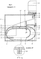
- FIGS. 6 and 8 show a second embodiment of the invention inventive hydraulic fluid machine with a Accelerator 11 and without vanes 2, which with a annular water circuit according to the invention with a radial, to a Axle 6 'of a generator 6, extending flow direction is equipped.
- the annular water cycle is different from that of the first one Embodiment in that instead of the guide vanes.
- an accelerator 11 is arranged with the impeller 3 about the axis 6 'of the generator 6, wherein the bottom of the flow area 8 opposite lying opening between the suction chamber 1 and Leitraum 7 through the horizontally about the axis 6 'rotating accelerator 11 and the Impeller 3 is covered and the transition from the Saugraumausgang 1 "to the acceleration wheel 11 according to Figure 9 by a non-contact Seal 24 is sealed.
- This embodiment is preferred then used when the water in the Leitraum 7 and the suction chamber. 1 should have a low flow rate. The circulation speed cu2 of the water 4 in the impeller 3 is then too low to prevent penetration of the atmospheric air pressure pL in the suction chamber 1 to avoid.
- the acceleration wheel 11 with inlet openings 11 'on Inner diameter D3 and outlet openings 11 "on the outer diameter D4 takes over in this case the additional acceleration of the Suction chamber 1 leaking water 4 from the inlet velocity c3 on the exit velocity c4 and the required Entry speed c1 of the water 4 in the impeller 3.
- this additional acceleration of the water 4 in the accelerator 11th also increases a circulation speed cu3 at the inner diameter D3 to a peripheral speed cu4 at the outer diameter D4 of Acceleration wheel 11.
- the orbital velocities cu3 and cu4 of the Water 4 in the accelerator 11 generate in this case, the Centrifugal force Fz, which by the apparent from Fig.7 blade assembly and Form in the accelerator wheel 11 and the impeller 3 is supported.
- the Energy required for this is supplied by the drive motor 5. Of the Energy amount is, however, by the larger torque output of the Impeller 3 to the generator 6 the drive motor 5 again for Provided. As a result, the services to be transferred in Drive motor 5, in the impeller 3 and in the generator 6 larger. Furthermore the power transmission of the acceleration wheel 11 still comes added. The energy losses increase significantly, causing the final energy EN to be given off from the atmospheric air pressure pL introduced and from the generator 6 a consumer available can be made is less than when running with Guide vanes 2.
- FIG. 10 shows a schematic of the resulting energy balance for a inventive hydraulic fluid machine without vanes 2 with an accelerator 11 after the second Embodiment, in addition to those already listed Influence factors the water density p, the efficiencies ⁇ of the Drive motor 5 and the generator 6 of the suction chamber 1, the impeller 3, and the accelerator 11 are taken into account.
Landscapes
- Engineering & Computer Science (AREA)
- Chemical & Material Sciences (AREA)
- Combustion & Propulsion (AREA)
- Mechanical Engineering (AREA)
- General Engineering & Computer Science (AREA)
- Hydraulic Turbines (AREA)
- Other Liquid Machine Or Engine Such As Wave Power Use (AREA)
- Fluid-Pressure Circuits (AREA)
- Lubrication Of Internal Combustion Engines (AREA)
- Cyclones (AREA)
Description
Aus der EP 0 545 280 A 1 ist auch eine Antriebsvorrichtung mit einer auf einer drehbaren Welle fest angeordneten Turbine bekannt, die durch eine Flüssigkeit, insbesondere Wasser beaufschlagbar und zusammen mit der Welle in eine Drehbewegung versetzbar ist, dadurch gekennzeichnet, daß die Welle senkrecht stehend angeordnet ist, daß auf der Welle diese konzentrisch umgebend eine nach obenhin sich konisch erweiternde Röhre fest angeordnet ist und die im oberen Randbereich einen Überlauf mit einem darunter angeordneten, feststehenden Sammelbehälter für überlaufende Flüssigkeit aufweist, und daß die Turbine über wenigstens ein, vom Sammelbehälter ausgehendes Fallrohr von unten mit der Flüssigkeit beaufschlagbar ist.
Die DE 196 47 476 A1 offenbart einen pneumatisch hydraulischen Zentrifugalantrieb für alle Arten der Energiebewegung und Energieerzeugung, dadurch gekennzeichnet, daß durch einen Rotor mit einer oder mehreren integrierten Kammern/Tanks Wasser, Öl oder andere Flüssigkeiten aufnehmen und durch Beschleunigung zentrifugiert/verdichtet und in ein unter Druck stehendes Gehäuse preßt, wobei das Gehäuse, in dem der Rotor angetrieben wird unter Luftdruck oder Gasdruck steht und mit Wasser oder anderen Flüssigkeiten gefüllt ist. Die Kammern des Rotors werden über die Rotorachse mit Flüssigkeit gefüllt und durch die Drehbewegung des Rotors nach außen geschleudert, wodurch Fliehkräfte entstehen, die das Wasser über die an den Kammern angeordneten Düsen aus dem Rotor in das unter Druck stehende Gehäuse schleudern, an dessen Boden sich das Wasser sammelt und einer Turbine zugeführt wird, die das Wasser an einen Energieerzeuger und gleichzeitig in die Rotorachse zurückführt.
Die voranbeschriebenen Lösungen gehen von dem Grundprinzip des Auftriebs einer Wassersäule im Zentrum um eine rotierende Achse aus, von wo aus die Flüssigkeit radial in ein Turbinenrad geführt und durch Fliehkrafte nach außen gedrückt wird, wobei die oben beschriebenen Nachteile auftreten.
Auch die in der WO 00/29747 beschriebene hydraulische Strömungsmaschine kann diese Nachteile nicht beseitigen, da bei dieser Lösung das Wasser dem Saugraum nicht mit einer wannenförmigen Führung zugeführt wird, die Fliehkraft kein Kräftegleichgewicht mit dem atmosphärischen Luftdruck am Ausgang der Drehscheibe bildet und der Motor das Wasser in der Drehscheibe auf Austrittsgeschwindigkeit beschleunigen muß.
Der Erfindung liegt daher die Aufgabe zugrunde, eine hydraulische Strömungsmaschine zu schaffen die, ausschließlich die durch den atmosphärischen Luftdruck bedingte Beschleunigung des Strömungskreislaufes einer in einem Saugraum zu einem Laufrad aufsteigenden Wassersäule nutzt und als Endenergie einem Verbraucher zur Verfügung stellt.
Die Aufgabe wird durch eine hydraulische Strömungsmaschine mit den kennzeichnenden Merkmalen des Anspruchs 1 gelöst.
Besonders hervorzuheben ist, daß durch eine Öffnung zwischen den beiden inneren Führungswänden vor dem Eingang des Saugraums innerhalb des wannenförmigen Strömungsraums der atmosphärische Luftdruck auf den Wasserspiegel wirken kann und ein zwischen Strömungsraum und Behälter angeordnetes Ausgleichsrohr ermöglicht die Regulierbarkeit des Wasserspiegels im wannenförmigen Strömungsraum. Dabei ist die Höhe des Wasserfüllstandes im Behälter durch bekannte Methoden wie manuell durch ein Sichtfenster oder über entsprechend angeordnete Schwimmer oder über Sensoren, die bei Erreichung eines bestimmbaren Pegels ein Signal auslösen sowie durch ein den Anwendungsbedingungen angepasstes Wasserzulauf- und Wasserablaufsystem optimal bestimmbar. Der atmosphärische Luftdruck übt einen Druck auf den im wannenförmigen Strömungsraum befindlichen Wasserspiegel aus und bewirkt, daß, bedingt durch das vom Laufrad erzeugte Kräftegleichgewicht, das Wasser im Saugraum beschleunigt wird, über die Leitschaufeln in das horizontal um die Achse des Generators rotierende Laufrad und von diesem in den Leitraum geleitet wird, wo es umgelenkt und dem Saugraum wieder zugeführt werden kann.
Dabei addiert sich die Geschwindigkeitsenergie der Austrittsgeschwindigkeit des Wassers aus dem Laufrad mit der Druckenergie des atmosphärischen Luftrucks und durch Querschnittsverengung im Leitschaufelbereich wird das Wasser wieder auf die erforderliche Eintrittsgeschwindigkeit in das Laufrad beschleunigt.
- Fig. 1
- einen Schnitt durch die hydraulische Strömungsmaschine mit Leitschaufeln und ohne Beschleunigungsrad,
- Fig. 2
- einen Schnitt A-B aus Fig.1,
- Fig. 3
- einen Teilschnitt C- D aus Fig.1,
- Fig. 4
- einen Ausschnitt Z aus Fig.3,
- Fig. 5
- die Energiebilanz der erfindungsgemäßen hydraulischen Strömungsmaschine mit Leitschaufeln,
- Fig. 6
- einen Schnitt durch die hydraulische Strömungsmaschinen ohne Leitschaufeln mit Beschleunigungsrad,
- Fig. 7
- einen Schnitt E- F aus Fig.6,
- Fig. 8
- einen Teilschnitt G- H aus Fig.6,
- Fig. 9
- einen Ausschnitt W aus Fig.8,
- Fig. 10
- eine Energiebilanz der hydraulischen Strömungsmaschine mit Beschleunigungsrad.
- 1
- Saugraum,
- 1'
- Saugraumeingang,
- 1"
- Saugraumausgang,
- 2
- Leitschaufeln,
- 2'
- Leitschaufelausgang,
- 3
- Laufrad,
- 3'
- Laufradschaufeln,
- 3"
- Eintrittsöffnungen,
- 3'"
- Austrittsöffnungen,
- 4
- Wasser,
- 4'
- Wasserspiegel,
- 5
- Antriebsmotor,
- 6
- Generator,
- 6'
- Achse des Generators,
- 7
- Leitraum,
- 7'
- Leiraumeingang,
- 7"
- Leitraumausgang,
- 8
- Strömungsraum,
- 8'
- äußere Führungswand,
- 8"
- innere Führungswand,
- 8'"
- innere Führungswand
- 9
- Behälter,
- 10
- Ausgleichsrohr,
- 11
- Beschleunigungsrad,
- 11'
- Eintrittsöffnungen des Beschleunigungsrads,
- 11"
- Austrittsöffnungen des Beschleunigungsrads,
- 12
- Behälterkammer,
- 13
- Behälterkammer,
- 14
- Wegeventil,
- 15
- Rückschlagventil,
- 16
- Pumpe,
- 17
- Führungsstege,
- 18
- Führungsstege,
- 19
- Führungsstege,
- 20
- Riemenscheibe,
- 21
- Riemen,
- 22
- Kupplung,
- 23
- Lager,
- 24
- Dichtung,
- D1
- Innendurchmesser des Laufrads,
- D2
- Außendurchmesser des Laufrads,
- D3
- Innendurchmesser des Beschleunigungsrads,
- D4
- Außendurchmesser des Beschleunigungsrads,
- c1
- Eintrittsgeschwindigkeit in das Laufrad,
- c2
- Austrittsgeschwindigkeit aus dem Laufrad,
- c3
- Eintrittsgeschwindigkeit in das Beschleunigungsrad,
- c4
- Austrittsgeschwindigkeit aus dem Beschleunigungsrad,
- cu1
- Umlaufgeschwindigkeit am Eingang des Laufrads,
- cu2
- Umlaufgeschwindigkeit am Ausgang des Laufrads,
- cu3
- Umlaufgeschwindigkeit am Eingang des Beschleunigungsrads,
- cu4
- Umlaufgeschwindigkeit am Ausgang des Beschleunigungsrads,
- u1
- Umlaufgeschwindigkeit am D1 des Laufrads,
- u2
- Umlaufgeschwindigkeit am D2 des Laufrads,
- u3
- Umlaufgeschwindigkeit am D3 des Beschleunigungsrads,
- u4
- Umlaufgeschwindigkeit am D4 des Beschleunigungsrads,
- w
- Fließgeschwindigkeit des Wassers an der Schaufelwand,
- α1
- Eintrittswinkel am Laufrad.
- α2
- Austrittswinkel am Laufrad,
- α3
- Eintrittswinkel am Beschleunigungsrad,
- α4
- Austrittswinkel am Beschleunigungsrad,
- β1
- Schaufelwinkel am Eingang des Laufrads,
- β2
- Schaufelwinkel am Ausgang des Laufrads,
- β3
- Schaufelwinkel am Ausgang des Beschleunigungsrads,
- β4
- Schaufelwinkel am Eingang des Beschleunigungsrads,
- pL
- atmosphärische Luftdruck,
- ρ
- Dichte des Wassers,
- Fz
- Fliehkraft,
- pz
- Druck der Fliehkraft,
- η
- Wirkungsgrad,
- Em
- Energie des Antriebsmotors,
- Etv
- Verlust Turbine,
- Emv
- Verlust Antriebsmotor,
- Ebv
- Verlust Beschleunigungsrad,
- Egv
- Verlust Generator,
- EN
- Endenergie.
Claims (5)
- Hydraulische Strömungsmaschine, bestehend aus einer Welle (6'), einem Saugraum (1), Leitschaufeln (2) und einem rotierenden Laufrad (3) mit Laufradschaufeln (3'), die mit Wasser (4) gefüllt sind, einem Antriebsmotor (5) und einem Generator (6), einem ringförmigen Wasserkreislauf, mit radial zu einer Achse (6') des Generators (6), verlaufender Flußrichtung, einem Leitraum (7), einem Strömungsraum (8), die koaxial um die Achse (6') des Generators (6) in einem Behälter (9) angeordnet sind dadurch gekennzeichnet, daß der Strömungsraum (8) wannenförmig ausgebildet und vor einem Saugraumeingang (1') des Saugraums (1) mit einer Öffnung ausgestattet ist, in der ein Wasserspiegel (4') zum Behälter (9) regulierbar ist,
daß im Leitraum (7) das aus dem Laufrad (3) antretende Wasser (4) über einen Leitraumausgang (7") des Leitraums (7) zu dem Saugraumeingang (1') lenkbar und dem Saugraum (1) wieder zuführbar ist,
daß der Antriebsmotor (5) das Laufrad (3) auf einer bestimmten Drehzahl hält, um ein Kräftegleichgewicht zwischen dem atmosphärischen Luftdruck als Zentripetalkraft und der Fliehkraft an Austrittsöffnungen (3"') des Laufrads (3) zu erreichen und
daß zwischen zugeführter Energie an Eintrittsöffnungen (3") und abgeführter Energie an den Austrittsöffnungen (3"') des Laufrads (3) eine Energiedifferenz entsteht, die der Summe einer am Saugraumeingang (1') eingebrachten Druckenergie des atmosphärischen Luftdrucks (pL) und einer eingebrachten Energie (EM) des Antriebsmotors (5) entspricht und die als Drehmoment vom Laufrad (3) auf den Generator (6) übertragbar ist. - Hydraulische Strömungsmaschine nach Anspruch 1, dadurch gekennzeichnet, daß der wannenförmige Strömungsraum (8) aus einer äußeren Führungswand (8') besteht, die mit einer inneren Führungswand (8") den Saugraum (1) mit Leitschaufeln (2) und mit einer inneren Führungswand (8"') den Leitraum (7) erfaßt, wobei zwischen Saugraum (1) mit Leitschaufeln (2) und Leitraum (7) das Laufrad (3) rotierend angeordnet ist, die zusammen den ringförmigen Wasserkreislauf bilden.
- Hydraulische Strömungsmaschine nach Anspruch 2, dadurch gekennzeichnet, daß die innere Führungswand (8") durch die Leitschaufeln (2) mit der äußeren Führungswand (8') und die innere Führungswand (8'") durch Führungsstege (17) mit der äußeren Führungswand (8') verbunden sind oder daß die innere Führungswand (8") durch Führungsstege (18) mit der äußeren Führungswand (8') und die innere Führungswand (8"') durch Führungsstege (19) mit der äußeren Führungswand (8') verbunden sind.
- Hydraulische Strömungsmaschine nach Anspruch 1, dadurch gekennzeichnet, daß bei einer reduzierten Austrittsgeschwindigkeit (c2) des Wassers (4) aus dem Laufrad (3) statt der Leitschaufeln (2) ein Beschleunigungsrad (11) die fehlende Geschwindigkeitsenergie für die Eintrittsgeschwindigkeit (c1) des Wassers (4) in das Laufrad (3) mit dem Antriebsmotor (5) kompensiert, wobei das Beschleunigungsrad (11) mit dem Laufrad (3) horizontal um die Achse (6') des Generators (6) rotiert.
- Hydraulische Strömungsmaschine nach Anspruch 1, dadurch gekennzeichnet, daß die vom Antriebsmotor (5) eingebrachte Energie (EM) durch den Generator (6) wieder an den Antriebsmotor (5) zurückführbar ist und ausschließlich die in den Saugraum (1) eingebrachte Druckenergie des atmosphärischen Luftdrucks (pL), reduziert um alle auftretenden Energieverluste, vom Generator (6) als Endenergie (EN) einem Verbraucher zuführbar ist.
Applications Claiming Priority (5)
| Application Number | Priority Date | Filing Date | Title |
|---|---|---|---|
| DE10034219 | 2000-07-13 | ||
| DE10034219 | 2000-07-13 | ||
| DE10129830 | 2001-06-25 | ||
| DE10129830A DE10129830A1 (de) | 2000-07-13 | 2001-06-25 | Hydraulische Strömungsmaschine |
| PCT/EP2001/007849 WO2002006666A1 (de) | 2000-07-13 | 2001-07-09 | Hydrauliche strömungsmaschine |
Publications (2)
| Publication Number | Publication Date |
|---|---|
| EP1299642A1 EP1299642A1 (de) | 2003-04-09 |
| EP1299642B1 true EP1299642B1 (de) | 2005-12-07 |
Family
ID=26006384
Family Applications (1)
| Application Number | Title | Priority Date | Filing Date |
|---|---|---|---|
| EP01967133A Expired - Lifetime EP1299642B1 (de) | 2000-07-13 | 2001-07-09 | HYDRAULISCHE STRöMUNGSMASCHINE |
Country Status (6)
| Country | Link |
|---|---|
| EP (1) | EP1299642B1 (de) |
| AT (1) | ATE312283T1 (de) |
| AU (1) | AU2001287588A1 (de) |
| DE (1) | DE50108325D1 (de) |
| ES (1) | ES2254479T3 (de) |
| WO (1) | WO2002006666A1 (de) |
Families Citing this family (2)
| Publication number | Priority date | Publication date | Assignee | Title |
|---|---|---|---|---|
| NL2025860B1 (nl) * | 2020-06-18 | 2022-02-17 | Arnbarg Beheer B V | Vortex motor |
| WO2021256924A1 (en) * | 2020-06-18 | 2021-12-23 | Arnbarg Beheer B.V. | Vortex motor |
Family Cites Families (9)
| Publication number | Priority date | Publication date | Assignee | Title |
|---|---|---|---|---|
| DE195199C (de) | ||||
| DE260261C (de) | ||||
| BE337974A (de) * | ||||
| DE414415C (de) | 1925-05-30 | Hermann Schnaidt | Mehroktavige diatonische Harmonika | |
| FR2395407A2 (fr) * | 1977-02-11 | 1979-01-19 | Commins Eric | Moteur d'energie mecanique (a action hydraulique) |
| JPS56118566A (en) * | 1980-02-22 | 1981-09-17 | Kiyotatsu Fukai | Rotary hydraulic machine |
| DE4139633A1 (de) * | 1991-12-02 | 1993-08-12 | Willi Maurer | Antriebsvorrichtung |
| DE19647476A1 (de) * | 1996-11-16 | 1998-05-20 | Manfred Klenk | Pneumatisch hydraulischer Zentrifugalantrieb |
| WO2000029747A2 (de) * | 1998-11-10 | 2000-05-25 | Johannes Van Berkum | Hydraulische strömungsmaschine |
-
2001
- 2001-07-09 AU AU2001287588A patent/AU2001287588A1/en not_active Abandoned
- 2001-07-09 AT AT01967133T patent/ATE312283T1/de not_active IP Right Cessation
- 2001-07-09 ES ES01967133T patent/ES2254479T3/es not_active Expired - Lifetime
- 2001-07-09 WO PCT/EP2001/007849 patent/WO2002006666A1/de not_active Ceased
- 2001-07-09 EP EP01967133A patent/EP1299642B1/de not_active Expired - Lifetime
- 2001-07-09 DE DE50108325T patent/DE50108325D1/de not_active Expired - Lifetime
Also Published As
| Publication number | Publication date |
|---|---|
| EP1299642A1 (de) | 2003-04-09 |
| DE50108325D1 (de) | 2006-01-12 |
| ATE312283T1 (de) | 2005-12-15 |
| AU2001287588A1 (en) | 2002-01-30 |
| ES2254479T3 (es) | 2006-06-16 |
| WO2002006666A1 (de) | 2002-01-24 |
Similar Documents
| Publication | Publication Date | Title |
|---|---|---|
| EP2297451B1 (de) | Strömungswandler | |
| EP1440240B1 (de) | Generator für ein wasserkraftwerk | |
| EP0363309B1 (de) | Peltonturbine | |
| DE60033850T2 (de) | Reibungsrotorkomponenten für pumpen, turbinen und getriebe | |
| EP2179171A1 (de) | Tauchende energieerzeugungsanlage, angetrieben durch eine wasserströmung | |
| AT515217B1 (de) | Vorrichtung und Verfahren zum Umwandeln thermischer Energie | |
| US1993741A (en) | Fluid torque converter | |
| EP2722482B1 (de) | Rotationskolben-Verdrängermaschine | |
| EP1299642B1 (de) | HYDRAULISCHE STRöMUNGSMASCHINE | |
| US4217077A (en) | Two-stage/single-stage reversible pump-turbine with supplying pump | |
| US20060245919A1 (en) | Water wheel motor | |
| DE10129830A1 (de) | Hydraulische Strömungsmaschine | |
| KR101871703B1 (ko) | 수력 발전시스템 | |
| DE102019123491A1 (de) | Hybridmodul mit integrierter Hydraulik und integrierten Steuerelementen | |
| DE102018123620B4 (de) | Turbinenanordnung | |
| DE102021126542A1 (de) | Turbinenanordnung | |
| DE102010024621B4 (de) | Energiewandler | |
| WO2020008238A1 (en) | Shaft-less turbo-machines & propulsion systems | |
| JP7329117B1 (ja) | 動力供給システム及び発電システム | |
| US3936224A (en) | Power turbine | |
| RU2173745C2 (ru) | Бесплотинная гидроэлектростанция | |
| DE3017357A1 (de) | Hydrodynamischer energiewandler mit integrierter leistungsregelung | |
| DE911598C (de) | Fluessigkeitsturbine | |
| DE3243169A1 (de) | Stroemungsmaschine | |
| EP0636787A1 (de) | Unidirektionale Pumpturbine |
Legal Events
| Date | Code | Title | Description |
|---|---|---|---|
| PUAI | Public reference made under article 153(3) epc to a published international application that has entered the european phase |
Free format text: ORIGINAL CODE: 0009012 |
|
| 17P | Request for examination filed |
Effective date: 20030111 |
|
| AK | Designated contracting states |
Kind code of ref document: A1 Designated state(s): AT BE CH CY DE DK ES FI FR GB GR IE IT LI LU MC NL PT SE TR Designated state(s): AT BE CH CY DE DK ES FI FR GB GR IE IT LI LU MC NL PT SE TR |
|
| AX | Request for extension of the european patent |
Extension state: AL LT LV MK RO SI |
|
| 17Q | First examination report despatched |
Effective date: 20041108 |
|
| GRAP | Despatch of communication of intention to grant a patent |
Free format text: ORIGINAL CODE: EPIDOSNIGR1 |
|
| GRAS | Grant fee paid |
Free format text: ORIGINAL CODE: EPIDOSNIGR3 |
|
| GRAA | (expected) grant |
Free format text: ORIGINAL CODE: 0009210 |
|
| AK | Designated contracting states |
Kind code of ref document: B1 Designated state(s): AT BE CH CY DE DK ES FI FR GB GR IE IT LI LU MC NL PT SE TR |
|
| PG25 | Lapsed in a contracting state [announced via postgrant information from national office to epo] |
Ref country code: IE Free format text: LAPSE BECAUSE OF FAILURE TO SUBMIT A TRANSLATION OF THE DESCRIPTION OR TO PAY THE FEE WITHIN THE PRESCRIBED TIME-LIMIT Effective date: 20051207 Ref country code: FI Free format text: LAPSE BECAUSE OF FAILURE TO SUBMIT A TRANSLATION OF THE DESCRIPTION OR TO PAY THE FEE WITHIN THE PRESCRIBED TIME-LIMIT Effective date: 20051207 |
|
| REG | Reference to a national code |
Ref country code: GB Ref legal event code: FG4D Free format text: NOT ENGLISH |
|
| REG | Reference to a national code |
Ref country code: CH Ref legal event code: EP |
|
| REG | Reference to a national code |
Ref country code: IE Ref legal event code: FG4D Free format text: LANGUAGE OF EP DOCUMENT: GERMAN |
|
| REF | Corresponds to: |
Ref document number: 50108325 Country of ref document: DE Date of ref document: 20060112 Kind code of ref document: P |
|
| REG | Reference to a national code |
Ref country code: CH Ref legal event code: NV Representative=s name: PATENTANWAELTE SCHAAD, BALASS, MENZL & PARTNER AG |
|
| PG25 | Lapsed in a contracting state [announced via postgrant information from national office to epo] |
Ref country code: SE Free format text: LAPSE BECAUSE OF FAILURE TO SUBMIT A TRANSLATION OF THE DESCRIPTION OR TO PAY THE FEE WITHIN THE PRESCRIBED TIME-LIMIT Effective date: 20060307 Ref country code: GR Free format text: LAPSE BECAUSE OF FAILURE TO SUBMIT A TRANSLATION OF THE DESCRIPTION OR TO PAY THE FEE WITHIN THE PRESCRIBED TIME-LIMIT Effective date: 20060307 Ref country code: DK Free format text: LAPSE BECAUSE OF FAILURE TO SUBMIT A TRANSLATION OF THE DESCRIPTION OR TO PAY THE FEE WITHIN THE PRESCRIBED TIME-LIMIT Effective date: 20060307 |
|
| GBT | Gb: translation of ep patent filed (gb section 77(6)(a)/1977) |
Effective date: 20060309 |
|
| PG25 | Lapsed in a contracting state [announced via postgrant information from national office to epo] |
Ref country code: PT Free format text: LAPSE BECAUSE OF FAILURE TO SUBMIT A TRANSLATION OF THE DESCRIPTION OR TO PAY THE FEE WITHIN THE PRESCRIBED TIME-LIMIT Effective date: 20060508 |
|
| REG | Reference to a national code |
Ref country code: ES Ref legal event code: FG2A Ref document number: 2254479 Country of ref document: ES Kind code of ref document: T3 |
|
| PGFP | Annual fee paid to national office [announced via postgrant information from national office to epo] |
Ref country code: CH Payment date: 20060724 Year of fee payment: 6 |
|
| PGFP | Annual fee paid to national office [announced via postgrant information from national office to epo] |
Ref country code: AT Payment date: 20060725 Year of fee payment: 6 |
|
| PG25 | Lapsed in a contracting state [announced via postgrant information from national office to epo] |
Ref country code: MC Free format text: LAPSE BECAUSE OF NON-PAYMENT OF DUE FEES Effective date: 20060731 |
|
| ET | Fr: translation filed | ||
| REG | Reference to a national code |
Ref country code: IE Ref legal event code: FD4D |
|
| PLBE | No opposition filed within time limit |
Free format text: ORIGINAL CODE: 0009261 |
|
| STAA | Information on the status of an ep patent application or granted ep patent |
Free format text: STATUS: NO OPPOSITION FILED WITHIN TIME LIMIT |
|
| 26N | No opposition filed |
Effective date: 20060908 |
|
| REG | Reference to a national code |
Ref country code: CH Ref legal event code: PL |
|
| PG25 | Lapsed in a contracting state [announced via postgrant information from national office to epo] |
Ref country code: LI Free format text: LAPSE BECAUSE OF NON-PAYMENT OF DUE FEES Effective date: 20070731 Ref country code: CH Free format text: LAPSE BECAUSE OF NON-PAYMENT OF DUE FEES Effective date: 20070731 |
|
| PG25 | Lapsed in a contracting state [announced via postgrant information from national office to epo] |
Ref country code: AT Free format text: LAPSE BECAUSE OF NON-PAYMENT OF DUE FEES Effective date: 20070709 |
|
| PG25 | Lapsed in a contracting state [announced via postgrant information from national office to epo] |
Ref country code: TR Free format text: LAPSE BECAUSE OF FAILURE TO SUBMIT A TRANSLATION OF THE DESCRIPTION OR TO PAY THE FEE WITHIN THE PRESCRIBED TIME-LIMIT Effective date: 20051207 Ref country code: LU Free format text: LAPSE BECAUSE OF NON-PAYMENT OF DUE FEES Effective date: 20060709 |
|
| PG25 | Lapsed in a contracting state [announced via postgrant information from national office to epo] |
Ref country code: CY Free format text: LAPSE BECAUSE OF FAILURE TO SUBMIT A TRANSLATION OF THE DESCRIPTION OR TO PAY THE FEE WITHIN THE PRESCRIBED TIME-LIMIT Effective date: 20051207 |
|
| PGFP | Annual fee paid to national office [announced via postgrant information from national office to epo] |
Ref country code: BE Payment date: 20090622 Year of fee payment: 9 |
|
| PGFP | Annual fee paid to national office [announced via postgrant information from national office to epo] |
Ref country code: NL Payment date: 20090724 Year of fee payment: 9 |
|
| PGFP | Annual fee paid to national office [announced via postgrant information from national office to epo] |
Ref country code: ES Payment date: 20100715 Year of fee payment: 10 |
|
| PGFP | Annual fee paid to national office [announced via postgrant information from national office to epo] |
Ref country code: IT Payment date: 20100726 Year of fee payment: 10 |
|
| BERE | Be: lapsed |
Owner name: *VAN BERKUM JOHANNES Effective date: 20100731 |
|
| REG | Reference to a national code |
Ref country code: NL Ref legal event code: V1 Effective date: 20110201 |
|
| PG25 | Lapsed in a contracting state [announced via postgrant information from national office to epo] |
Ref country code: NL Free format text: LAPSE BECAUSE OF NON-PAYMENT OF DUE FEES Effective date: 20110201 |
|
| PG25 | Lapsed in a contracting state [announced via postgrant information from national office to epo] |
Ref country code: BE Free format text: LAPSE BECAUSE OF NON-PAYMENT OF DUE FEES Effective date: 20100731 |
|
| PGFP | Annual fee paid to national office [announced via postgrant information from national office to epo] |
Ref country code: GB Payment date: 20110613 Year of fee payment: 11 |
|
| PGFP | Annual fee paid to national office [announced via postgrant information from national office to epo] |
Ref country code: FR Payment date: 20110725 Year of fee payment: 11 |
|
| PG25 | Lapsed in a contracting state [announced via postgrant information from national office to epo] |
Ref country code: IT Free format text: LAPSE BECAUSE OF NON-PAYMENT OF DUE FEES Effective date: 20110709 |
|
| REG | Reference to a national code |
Ref country code: ES Ref legal event code: FD2A Effective date: 20121122 |
|
| PGFP | Annual fee paid to national office [announced via postgrant information from national office to epo] |
Ref country code: DE Payment date: 20120921 Year of fee payment: 12 |
|
| PG25 | Lapsed in a contracting state [announced via postgrant information from national office to epo] |
Ref country code: ES Free format text: LAPSE BECAUSE OF NON-PAYMENT OF DUE FEES Effective date: 20110710 |
|
| GBPC | Gb: european patent ceased through non-payment of renewal fee |
Effective date: 20120709 |
|
| REG | Reference to a national code |
Ref country code: FR Ref legal event code: ST Effective date: 20130329 |
|
| PG25 | Lapsed in a contracting state [announced via postgrant information from national office to epo] |
Ref country code: GB Free format text: LAPSE BECAUSE OF NON-PAYMENT OF DUE FEES Effective date: 20120709 Ref country code: FR Free format text: LAPSE BECAUSE OF NON-PAYMENT OF DUE FEES Effective date: 20120731 |
|
| REG | Reference to a national code |
Ref country code: DE Ref legal event code: R119 Ref document number: 50108325 Country of ref document: DE Effective date: 20140201 |
|
| PG25 | Lapsed in a contracting state [announced via postgrant information from national office to epo] |
Ref country code: DE Free format text: LAPSE BECAUSE OF NON-PAYMENT OF DUE FEES Effective date: 20140201 |