EP1299672B1 - Servolenkungsvorrichtung - Google Patents
Servolenkungsvorrichtung Download PDFInfo
- Publication number
- EP1299672B1 EP1299672B1 EP01941893A EP01941893A EP1299672B1 EP 1299672 B1 EP1299672 B1 EP 1299672B1 EP 01941893 A EP01941893 A EP 01941893A EP 01941893 A EP01941893 A EP 01941893A EP 1299672 B1 EP1299672 B1 EP 1299672B1
- Authority
- EP
- European Patent Office
- Prior art keywords
- projection
- conduit
- bead
- clip
- base
- Prior art date
- Legal status (The legal status is an assumption and is not a legal conclusion. Google has not performed a legal analysis and makes no representation as to the accuracy of the status listed.)
- Expired - Lifetime
Links
- 239000012530 fluid Substances 0.000 claims abstract description 9
- 239000011324 bead Substances 0.000 claims description 54
- 238000010276 construction Methods 0.000 description 7
- 238000004080 punching Methods 0.000 description 6
- 230000000712 assembly Effects 0.000 description 2
- 238000000429 assembly Methods 0.000 description 2
- 238000005219 brazing Methods 0.000 description 1
- 230000008878 coupling Effects 0.000 description 1
- 238000010168 coupling process Methods 0.000 description 1
- 238000005859 coupling reaction Methods 0.000 description 1
- 230000001419 dependent effect Effects 0.000 description 1
- 239000002184 metal Substances 0.000 description 1
- 238000012986 modification Methods 0.000 description 1
- 230000004048 modification Effects 0.000 description 1
Images

Classifications
-
- F—MECHANICAL ENGINEERING; LIGHTING; HEATING; WEAPONS; BLASTING
- F16—ENGINEERING ELEMENTS AND UNITS; GENERAL MEASURES FOR PRODUCING AND MAINTAINING EFFECTIVE FUNCTIONING OF MACHINES OR INSTALLATIONS; THERMAL INSULATION IN GENERAL
- F16L—PIPES; JOINTS OR FITTINGS FOR PIPES; SUPPORTS FOR PIPES, CABLES OR PROTECTIVE TUBING; MEANS FOR THERMAL INSULATION IN GENERAL
- F16L37/00—Couplings of the quick-acting type
- F16L37/08—Couplings of the quick-acting type in which the connection between abutting or axially overlapping ends is maintained by locking members
- F16L37/12—Couplings of the quick-acting type in which the connection between abutting or axially overlapping ends is maintained by locking members using hooks, pawls, or other movable or insertable locking members
- F16L37/1225—Couplings of the quick-acting type in which the connection between abutting or axially overlapping ends is maintained by locking members using hooks, pawls, or other movable or insertable locking members using a retaining member the extremities of which, e.g. in the form of a U, engage behind a shoulder of both parts
-
- B—PERFORMING OPERATIONS; TRANSPORTING
- B62—LAND VEHICLES FOR TRAVELLING OTHERWISE THAN ON RAILS
- B62D—MOTOR VEHICLES; TRAILERS
- B62D5/00—Power-assisted or power-driven steering
- B62D5/06—Power-assisted or power-driven steering fluid, i.e. using a pressurised fluid for most or all the force required for steering a vehicle
- B62D5/062—Details, component parts
-
- F—MECHANICAL ENGINEERING; LIGHTING; HEATING; WEAPONS; BLASTING
- F16—ENGINEERING ELEMENTS AND UNITS; GENERAL MEASURES FOR PRODUCING AND MAINTAINING EFFECTIVE FUNCTIONING OF MACHINES OR INSTALLATIONS; THERMAL INSULATION IN GENERAL
- F16L—PIPES; JOINTS OR FITTINGS FOR PIPES; SUPPORTS FOR PIPES, CABLES OR PROTECTIVE TUBING; MEANS FOR THERMAL INSULATION IN GENERAL
- F16L37/00—Couplings of the quick-acting type
- F16L37/08—Couplings of the quick-acting type in which the connection between abutting or axially overlapping ends is maintained by locking members
- F16L37/084—Couplings of the quick-acting type in which the connection between abutting or axially overlapping ends is maintained by locking members combined with automatic locking
- F16L37/098—Couplings of the quick-acting type in which the connection between abutting or axially overlapping ends is maintained by locking members combined with automatic locking by means of flexible hooks
- F16L37/0985—Couplings of the quick-acting type in which the connection between abutting or axially overlapping ends is maintained by locking members combined with automatic locking by means of flexible hooks the flexible hook extending radially inwardly from an outer part and engaging a bead, recess or the like on an inner part
-
- Y—GENERAL TAGGING OF NEW TECHNOLOGICAL DEVELOPMENTS; GENERAL TAGGING OF CROSS-SECTIONAL TECHNOLOGIES SPANNING OVER SEVERAL SECTIONS OF THE IPC; TECHNICAL SUBJECTS COVERED BY FORMER USPC CROSS-REFERENCE ART COLLECTIONS [XRACs] AND DIGESTS
- Y10—TECHNICAL SUBJECTS COVERED BY FORMER USPC
- Y10S—TECHNICAL SUBJECTS COVERED BY FORMER USPC CROSS-REFERENCE ART COLLECTIONS [XRACs] AND DIGESTS
- Y10S285/00—Pipe joints or couplings
- Y10S285/921—Snap-fit
Definitions
- the present invention relates to a power steering apparatus, and more specifically to a power steering apparatus having a connector assembly which connects a conduit with a housing having a chamber which holds power steering fluid.
- a known power steering apparatus includes a hydraulic motor having a housing which encloses a chamber. Power steering fluid under pressure is conducted through a conduit to the chamber during turning of steerable vehicle wheels in one direction. Power steering fluid is conducted from the chamber through the conduit during turning of steerable vehicle wheels in the opposite direction. It is desirable to be able to quickly and securely interconnect the conduit and the housing.
- a known connection between a conduit for conducting power steering fluid and a housing includes a base fixedly connected with the housing.
- the base is welded to the housing to connect the base to the housing.
- a clip engages the base and the conduit to hold the conduit against movement relative to the housing.
- US 5,046,765 A discloses a tubular fitting used for the connection of pipes, which is formed such that if a main pipe and a branch pipe are inserted respectively within a through hole and a branch hole within the main fitting, and are coupled with the main fitting by means of the engaging body being engaged with the branch pipe and the branch pipe being engaged with the main pipe, the main pipe and the branch pipe can be securely connected by mechanical means without having to perform brazing operations.
- US 4,756,558 A discloses a quick connect tube coupling having a connector body with an external threaded portion and a passage extending therethrough.
- a sheet metal nut and tube retainer member has an opening therethrough with a helical edge engaging the external threaded portion to threadably connect the connector body and this member.
- the connector body passage is adapted to receive and telescopically pilot a tube end on opposite sides of an O-ring mounted in a groove in this passage.
- the O-ring is adapted to receive and peripherally seal the tube end.
- the nut and tube retainer has at least one integral retaining arm extending angularly inwardly toward the tube in the direction of entry thereof into the passage that terminates in a tip normally located in an interference position relative to the bead so as to be contacted and deflected outwardly thereby to permit continued entry of the tube end into the passage and after travel of the bead the repast to resume its interference position on the other side of the bead to retain the tube in the connector body.
- the present invention provides a power steering apparatus as set forth in claims 1 and 7. Preferred embodiments of the present invention may be gathered from the dependent claims.
- a vehicle power steering apparatus 10 ( Fig. 1 ) includes a power steering valve 12 which is connected with the outlet of a power steering pump (not shown) by a conduit 14.
- a second conduit 16 connects the power steering valve 12 with a reservoir for the pump.
- the power steering valve 12 controls the flow of fluid to and from a power steering motor 20.
- the power steering motor 20 could have many different constructions, in the illustrated embodiment of the invention, the power steering motor includes a cylindrical housing 22 which encloses a piston 24.
- the piston 24 is disposed in a chamber 25 in the housing 22.
- the piston 24 is connected with a rack bar 26 on which rack teeth 28 are disposed. Opposite ends of the rack bar 26 are connected with steerable vehicle wheels, in a known manner, by tie rods 32 and 34.
- the power steering valve 12 includes a valve housing 38 which encloses a rotatable valve core 40. An input end portion 42 of the valve core 40 is connected with a vehicle steering wheel. Upon rotation of the vehicle steering wheel, the power steering valve 12 is operable to connect either a conduit50 or a conduit 52 in fluid communication with the outlet from the power steering pump through the conduit 14. The other one of the conduits 50 and 52 is connected with the reservoir through the conduit 16.
- the general construction and mode of operation of the power steering apparatus 10 is well known. It is contemplated that the power steering apparatus 10 may have a construction and mode of operation which is generally similar to the construction and mode of operation of the power steering apparatus disclosed in U.S. Patent Nos. 5,505,276 and 4,276,812 .
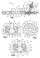
- Connector assemblies 60 ( Figs. 1 and 2 ) are provided to connect the conduits 50 and 52 with the housing 22.
- the connector assemblies 60 are identical and therefore, only the connector assembly connecting the conduit 50 with the housing 22 will be described in detail.
- the housing 22 has an opening 62 ( Fig. 2 ) defined by a projection 64 integrally formed on the housing 22.
- the projection 64 is formed on the housing 22 by punching the opening 62 in the housing from the inside of the housing outward. The projection 64 is then struck from the outside, while the housing 22 is supported from the inside, causing the top edge of the projection to roll over and form a radially extending lip 66.
- the connector assembly 60 includes a clip 68 engaging the projection 64 and a radially extending bead 70 on the conduit 50.
- the clip 68 presses the, bead 70 on the conduit 50 against an annular seal 72 to seal a joint between the projection 64 and the conduit 50.
- the seal 72 is pressed between the projection 64 and the bead 70.
- the clip 68 ( Figs. 2 and 3 ) includes a base 78 with an opening 79 through which the conduit 50 extends.
- a plurality of resilient fingers 80 extend from the base 78.
- Fig. 3 shows six fingers 80 extending from the base 78, however, two or more fingers could extend from the base.
- An axially extending cylindrical flange 84 ( Figs. 2 and 3 ) of the base 78 defines the opening 79. The flange 84 engages the bead 70 on the conduit 50 to press the conduit into the opening 62 in the housing 22.
- Each of the fingers 80 includes a radially inwardly extending portion 90.
- An end 91 of each of the fingers 80 extends radially inwardly and axially from the portion 90.
- the ends 91 of the fingers 80 engage a radially outwardly extending surface 92 ( Fig. 2 ) on the lip 66 of the projection 64.
- the projection 64 is integrally formed on the housing 22 by punching the opening 62 in the housing 22.
- the projection 64 is rolled over to form the lip 66.
- the clip 68 is placed on the conduit 50 with the conduit extending through the opening 79 in the base 68.
- the radially extending bead 70 is then formed on the conduit 50 to retain the clip 68 on the conduit 50.
- the seal 72 is then placed on the conduit 50 in engagement with the bead 70.
- the clip 68 is then slid along the conduit 50 until the flange 84 engages the bead 70.
- the conduit 50 is moved into the opening 62 in the projection 64.
- the clip 68 and conduit 50 are moved downward, as viewed in Fig. 2 , so that the ends 91 of the fingers 80 engage the lip 66 to cause the fingers to move radially outward.
- the clip 68 and the conduit 50 move further downward until the fingers 80 snap into engagement with the surface 92 on the lip 66 to prevent movement of the conduit relative to the housing 22.
- a second embodiment of a connector assembly for connecting the conduit 50 to the housing 22 of the power steering apparatus 10 is illustrated in Fig. 4 .
- a connector assembly 100 is provided to connect the conduit 50 with a projection 102 on the housing 22.
- the projection 102 is formed by punching an opening 104 in housing 22 from inside the housing outward.
- the projection 102 is struck from the outside to cause the top edge of the projection to roll over and form a lip 106.
- the connector assembly 100 includes a clip 108 engaging the projection 102 and a radially extending bead 110 formed on the conduit 50.
- the clip 108 is generally similar to the clip 68 illustrated in Figs. 2 and 3 .
- the clip 108 presses the bead 110 on the conduit 50 against an annular seal 112 to seal a joint between the projection 102 on the housing and the conduit 50.
- the seal 112 is pressed between the projection 102 and the bead 110.
- the clip 108 includes a base 118 with an opening 120 through which the projection 102 extends.
- a plurality of resilient fingers 122 extend from the base 118. It is contemplated that six fingers 122 extend from the base 118, however, two or more fingers 122 could extend from the base 118.
- An axially extending cylindrical flange 124 of the base 118 defines the opening 120 in the base 118. The flange 124 engages a radially extending surface 126 of the lip 106 to connect the clip 108 to the projection 102.
- Each of the resilient fingers 122 includes a radially inwardly extending portion 130. An end 132 of each of the fingers 122 extends radially inwardly and axially from the portion 130. The ends 132 of the fingers 122 engage the bead 110 on the conduit 50.
- the projection 102 is integrally formed on the housing 22 by punching the opening 104 in the hosing.
- the clip 108 is then placed on the projection 102 with the projection extending through the opening 120.
- An end of the projection 102 is struck from the outside to cause the end to roll over to form the lip 106 which retains the clip 108 on the housing 22.
- the bead 110 is formed on the conduit 50.
- the seal 112 is placed on the conduit 50 and into engagement with the bead 110.
- the conduit 50 is moved downward, as viewed in Fig. 4 , until the seal 112 engages the ends 132 of the resilient fingers 122.
- the resilient fingers 122 move radially outward upon engagement with the seal 112.
- the conduit 50 moves downward into the opening 104.
- the resilient fingers snap into engagement with the bead 110 to press the seal 112 between the bead and the projection 102 and prevent movement of the conduit relative to the housing.
- a connector assembly 150 is provided to connect the conduit 50 with a projection 152 ( Fig. 5 ) integrally formed on the housing 22.
- the projection 152 is formed by punching an opening 154 in the housing 22 from the inside of the housing outward.
- the connector assembly 150 includes a clip 158 engaging a radially extending bead 160 on the conduit 50 and the projection 152.
- the clip 158 presses the bead 160 on the conduit 50 against an annular seal 162 to seal a joint between the conduit 50 and the projection 152.
- the seal 162 is pressed between the bead 160 and a radially extending surface 164 on the projection 152.
- the clip 158 ( Figs. 5 and 6 ) includes a base 168 with an opening 169 through which the conduit 50 extends.
- a plurality of resilient fingers 170 extend from the base 168.
- Fig. 6 shows six fingers 170 extending from the base 168, however, two or more fingers could extend from the base.
- An axially extending cylindrical flange 174 of the base 168 defines the opening 169 in the base. The flange 174 engages the conduit 50.
- Each of the fingers 170 ( Fig. 5 ) includes a radially extending portion 180.
- Each of the fingers 170 has a radially extending surface 182. The surface 182 engages an axial end surface 186 of the projection 152 to retain the clip 158 in the opening 154.
- the projection 152 ( Fig. 5 ) includes a radially extending annular surface 200 axially spaced from the surface 164.
- An axially extending cylindrical surface 202 extends perpendicular to the surface 200.
- a radially extending annular surface 204 extends perpendicular to the cylindrical surface 202 and parallel to the surface 200.
- the surfaces 200, 202, and 204 define an annular recess 206 in the projection 152.
- the annular recess 206 receives the portions 180 on the fingers 170 to retain the conduit 50 in the opening 154.
- the projection 152 is integrally formed on the housing 22 by punching the opening 154 in the housing.
- the radially extending surface 164 and the annular recess 206 are formed on the projection 152.
- the clip 158 is placed on the conduit 50 with the conduit extending through the opening 169 in the base 168.
- the bead 160 is formed on the conduit 50 to retain the clip 158 on the conduit.
- the seal 162 is placed on the conduit 50 in engagement with the bead 160.
- the conduit 50 is then moved downward, as viewed in Fig. 5 , into the opening 154 until the seal 162 engages the surface 164.
- the clip 158 is then moved downward, as viewed in Fig. 5 , into the opening 154 in the projection 152 until the base 168 engages the bead 160.
- the portions 180 on the fingers 170 engage the surface 186 on the projection 152 to cause the fingers 170 to move radially inward.
- the portions 180 of the resilient fingers 170 snap into the recess 206 in the projection 152 to connect the conduit 50 with the projection 152.
Landscapes
- Engineering & Computer Science (AREA)
- General Engineering & Computer Science (AREA)
- Mechanical Engineering (AREA)
- Chemical & Material Sciences (AREA)
- Combustion & Propulsion (AREA)
- Transportation (AREA)
- Power Steering Mechanism (AREA)
Claims (12)
- Servolenkvorrichtung (10), die Folgendes aufweist:ein Gehäuse (22), welches eine Kammer (25) zum Aufnehmen der Servolenkflüssigkeit definiert, wobei das Gehäuse (22) eine Öffnung (62) besitzt, welche durch einen Vorsprung (64) definiert wird, welcher integral an dem Gehäuse (22) geformten ist, wobei der Vorsprung (64) einen Rand bzw. eine Lippe (66) mit einer sich radial erstreckenden unteren Oberfläche (92) aufweist;eine Rohrleitung (50), die sich in die Öffnung (62) hinein erstreckt, wobei die Rohrleitung (50) einen Wulst (70) aufweist, der sich radial nach außen von der Rohrleitung (50) erstreckt, wobei der Wulst (70) sich gegenüberliegende erste und zweite Seitenoberflächen aufweist;eine Verbinderanordnung (60), welche die Rohrleitung (50) mit dem Vorsprung (64) an dem Gehäuse (22) verbindet, wobei die Verbinderanordnung (60) eine Klemme bzw. Klammer (68) aufweist, die eine Basis (78) mit einer Öffnung (79) besitzt, wobei sich die Rohrleitung durch die Öffnung (79) in der Basis (78) erstreckt, und wobei ein Teil der Basis (78) der mit der ersten Seitenoberfläche des Wulstes (70) der Rohrleitung (50) in Eingriff steht; undeine ringförmige Dichtung (72), die sich zwischen dem Vorsprung (64) an dem Gehäuse (22) und der zweiten Seitenoberfläche des Wulstes (70) der Rohrleitung (50) befindet, wobei die zweite Seitenoberfläche des Wulstes (70) und der Vorsprung (64) gegenüberliegende Seitenteile der ringförmigen Dichtung (72) kontaktieren;dadurch gekennzeichnet, dassdie Klammer (68) ferner eine Vielzahl von elastischen Fingern (80) aufweist, die sich axial von der Basis (78) und über die zweite Seitenoberfläche des Wulstes (70) der Rohrleitung (50) hinaus erstrecken, wobei die Finger (80) Teile (90) aufweisen zum Einrasten über die Lippe (66) des Vorsprungs (64) an dem Gehäuse (22) und zum Eingreifen in die sich radial erstreckende untere Oberfläche (92) der Lippe (66), um die Rohrleitung (50) mit dem Vorsprung (64) zu verbinden;wobei die Klammer (68) derart bemessen ist, dass, wenn der Teil der Basis (78) der Klammer (68) mit der ersten Seitenoberfläche des Wulstes (70) der Rohrleitung (50) in Eingriff steht und die Teile (90) der Finger (80) der Klammer (68) mit der sich radial erstreckenden unteren Oberfläche (92) der Lippe (66) des Vorsprungs (64) in Eingriff stehen, die ringförmige Dichtung (72) axial durch den Wulst (70) und den Vorsprung (64) komprimiert wird und die Lippe (66) des Vorsprungs (64), der Wulst (70) der Rohrleitung (50) und die ringförmige Dichtung (72) insgesamt zwischen dem Teil der Basis (78) und den Teilen (90) der Finger (80) der Klammer (68) angeordnet sind.
- Servolenkvorrichtung (10) gemäß Anspruch 1, wobei der Teil der Basis (78) der Klammer (68) einen sich axial erstreckenden Flansch (84) aufweist, wobei der Flansch (84) die Öffnung (79) in der Basis (78) definiert.
- Servolenkvorrichtung (10) gemäß Anspruch 1, wobei jeder Finger der Finger (80) der Klammer (68) einen verjüngten Teil (91) aufweist, welcher, wenn er axial gegen den Vorsprung (64) an dem Gehäuse (22) gedrückt wird, den Finger radial nach außen vorspannt, um zu ermöglichen, dass der Finger über die Lippe (66) des Vorsprungs (64) schnappt bzw. einrastet.
- Servolenkvorrichtung (10) gemäß Anspruch 1, wobei die Öffnung (79) in der Basis (78) der Klammer (68) einen Durchmesser besitzt, der größer ist als ein Durchmesser der Rohrleitung (50) und kleiner ist als ein Durchmesser des Wulstes (70), wobei die Teile (90) der Finger (80) in der Gesamtheit eine Endöffnung der Klammer (68) definieren, wobei die Endöffnung einen Durchmesser besitzt, der größer ist als der Durchmesser der Rohrleitung (50) und kleiner ist als der Durchmesser des Wulstes (70).
- Servolenkvorrichtung (10) gemäß Anspruch 1, wobei die zweite Seitenoberfläche des Wulstes (70) und eine sich radial erstreckende obere Oberfläche des Vorsprungs (64) gegenüberliegende Oberflächenteile der ringförmigen Dichtung (72) kontaktieren, um den Wulst (70) von dem Vorsprung (64) zu beabstanden.
- Servolenkvorrichtung (10) gemäß Anspruch 5, wobei sich die zweite Seitenoberfläche des Wulstes (70) im Wesentlichen parallel zu der oberen Oberfläche des Vorsprungs (64) erstreckt, wenn die zweite Seitenoberfläche des Wulstes (70) und die obere Oberfläche des Vorsprungs (64) gegenüberliegende Oberflächenteile der ringförmigen Dichtung (72) kontaktieren.
- Servolenkvorrichtung (10), die Folgendes aufweist:ein Gehäuse (22), welches eine Kammer (25) zum Aufnehmen der Servolenkflüssigkeit definiert, wobei das Gehäuse (22) eine Öffnung (104) besitzt, welche durch einen an dem Gehäuse (22) geformten Vorsprung (102) definiert wird, wobei der Vorsprung (102) eine Lippe (106) mit einer sich radial erstreckenden unteren Oberfläche (126) und einer oberen Oberfläche aufweist;eine Rohrleitung (50), die sich in die Öffnung (104) hinein erstreckt, wobei die Rohrleitung (50) einen Wulst (110) aufweist, der sich radial nach außen von der Rohrleitung (50) erstreckt, wobei der Wulst (110) sich gegenüberliegende erste und zweite Seitenoberflächen aufweist;eine Verbinderanordnung (100), welche die Rohrleitung (50) mit dem Vorsprung (102) an dem Gehäuse (22) verbindet, wobei die Verbinderanordnung (100) eine Klammer (108) aufweist, die eine Basis (118) mit einer Öffnung (120) besitzt, wobei sich der Vorsprung (102) durch die Öffnung (120) in der Basis (118) erstreckt, und wobei ein Teil der Basis (118) mit der sich radial erstreckenden unteren Oberfläche (126) der Lippe (106) des Vorsprungs (102) in Eingriff steht; undeine ringförmige Dichtung (112), die sich zwischen dem Vorsprung (102) an dem Gehäuse (22) und der zweiten Seitenoberfläche des Wulstes (110) der Rohrleitung (50) befindet, wobei die zweite Seitenoberfläche des Wulstes (110) und der Vorsprung (102) gegenüberliegende Oberflächenteile der ringförmigen Dichtung (112) kontaktieren;dadurch gekennzeichnet, dassdie Klammer (108) ferner eine Vielzahl von elastischen Fingern (122) aufweist, die sich axial von der Basis (118) und über die zweite obere Oberfläche der Lippe (106) des Vorsprungs (102) hinaus erstrecken, wobei die Finger (122) Teile (130) aufweisen zum Einrasten über den Wulst (110) der Rohrleitung (50) und zum In-Eingriff-Bringen mit der ersten Seitenoberfläche des Wulstes (110), um die Rohrleitung (50) mit dem Vorsprung (102) zu verbinden;wobei die Klammer (108) derart bemessen ist, dass, wenn der Teil der Basis (118) der Klammer (108) mit der sich radial erstreckenden unteren Oberfläche des Vorsprungs (102) in Eingriff steht und die Teile (130) der Finger (122) der Klammer (108) mit der ersten Seitenoberfläche des Wulstes (110) der Rohrleitung (50) in Eingriff stehen, die ringförmige Dichtung (112) axial durch den Wulst (110) und den Vorsprung (102) komprimiert wird und die Lippe (106) des Vorsprungs (102), der Wulst (110) der Rohrleitung (50) und die ringförmige Dichtung (112) insgesamt zwischen dem Teil der Basis (118) und den Teilen (130) der Finger (122) der Klammer (108) angeordnet sind.
- Servolenkvorrichtung (10) gemäß Anspruch 7, wobei der Teil der Basis (118) der Klammer (108) einen sich axial erstreckenden Flansch (124) aufweist, wobei der Flansch (124) die Öffnung (120) in der Basis (118) definiert.
- Servolenkvorrichtung (10) gemäß Anspruch 7, wobei jeder Finger der Finger (122) der Klammer (108) einen verjüngten Teil (132) aufweist, welcher den Finger radial nach außen vorspannt, wenn er axial gegen den Wulst (110) der Rohrleitung (50) gedrückt wird.
- Servolenkvorrichtung (10) gemäß Anspruch 7, wobei die Öffnung (120) in der Basis (118) der Klammer (108) einen Durchmesser besitzt, der größer ist als ein Durchmesser des Vorsprungs (102) und kleiner ist als ein Durchmesser der Lippe (106) des Vorsprungs (102), wobei die Teile (130) der Finger (122) in der Gesamtheit eine Endöffnung der Klammer (108) definieren, wobei die Endöffnung einen Durchmesser besitzt, der kleiner ist als der Durchmesser der Lippe (106) des Vorsprungs (102).
- Servolenkvorrichtung (10) gemäß Anspruch 7, wobei die zweite Seitenoberfläche des Wulstes (110) und die obere Oberfläche des Vorsprungs (102) gegenüberliegende Oberflächenteile der ringförmigen Dichtung (112) kontaktieren, um den Wulst (110) von dem Vorsprung (102) zu beabstanden.
- Servolenkvorrichtung (10) gemäß Anspruch 11, wobei sich die zweite Seitenoberfläche des Wulstes (110) im Wesentlichen parallel zu der oberen Oberfläche des Vorsprungs (102) erstreckt, wenn die zweite Seitenoberfläche des Wulstes (110) und die obere Oberfläche des Vorsprungs (102) gegenüberliegende Oberflächenteile der ringförmigen Dichtung (112) kontaktieren.
Applications Claiming Priority (3)
| Application Number | Priority Date | Filing Date | Title |
|---|---|---|---|
| US592456 | 2000-06-09 | ||
| US09/592,456 US6655491B1 (en) | 2000-06-09 | 2000-06-09 | Power steering apparatus |
| PCT/US2001/018058 WO2001096775A1 (en) | 2000-06-09 | 2001-06-04 | Power steering apparatus |
Publications (3)
| Publication Number | Publication Date |
|---|---|
| EP1299672A1 EP1299672A1 (de) | 2003-04-09 |
| EP1299672A4 EP1299672A4 (de) | 2007-06-06 |
| EP1299672B1 true EP1299672B1 (de) | 2010-11-03 |
Family
ID=24370706
Family Applications (1)
| Application Number | Title | Priority Date | Filing Date |
|---|---|---|---|
| EP01941893A Expired - Lifetime EP1299672B1 (de) | 2000-06-09 | 2001-06-04 | Servolenkungsvorrichtung |
Country Status (5)
| Country | Link |
|---|---|
| US (1) | US6655491B1 (de) |
| EP (1) | EP1299672B1 (de) |
| AU (1) | AU2001275209A1 (de) |
| DE (1) | DE60143394D1 (de) |
| WO (1) | WO2001096775A1 (de) |
Families Citing this family (14)
| Publication number | Priority date | Publication date | Assignee | Title |
|---|---|---|---|---|
| WO2001028148A1 (en) * | 1999-10-11 | 2001-04-19 | Nokia Networks Oy | A method for identifying bad frames |
| DE10248014A1 (de) * | 2002-10-15 | 2004-05-13 | Trw Fahrwerksysteme Gmbh & Co Kg | Rohrverbindung und Verfahren zu ihrer Herstellung |
| DE10322972B4 (de) * | 2003-05-21 | 2013-12-24 | Continental Automotive Gmbh | Verbindungselement |
| FR2873780B1 (fr) * | 2004-07-29 | 2006-09-08 | Comap Sa | Bague de visualisation du sertissage d'un raccord pour tubes |
| US20060113792A1 (en) * | 2004-11-12 | 2006-06-01 | Enhanced Applications, L.C. | Quick connector fluid coupling |
| US7364204B2 (en) * | 2005-03-22 | 2008-04-29 | Trw Automotive U.S. Llc | Integrated transfer line for automotive steering system |
| US7888049B2 (en) * | 2006-02-07 | 2011-02-15 | Toxcure. LLC | Rapid nasal assay kit |
| US8162355B2 (en) * | 2008-03-05 | 2012-04-24 | Tk Holdings Inc. | Airbag inflator connector |
| US8469404B2 (en) * | 2010-08-23 | 2013-06-25 | Lg Chem, Ltd. | Connecting assembly |
| US8758922B2 (en) | 2010-08-23 | 2014-06-24 | Lg Chem, Ltd. | Battery system and manifold assembly with two manifold members removably coupled together |
| US8920956B2 (en) | 2010-08-23 | 2014-12-30 | Lg Chem, Ltd. | Battery system and manifold assembly having a manifold member and a connecting fitting |
| DE102012104288A1 (de) * | 2012-05-16 | 2013-11-21 | Voss Automotive Gmbh | "Steckverbindung für Fluid-Leitungen und Halteteil für eine derartige Steckverbindung" |
| DE102012213089A1 (de) * | 2012-07-25 | 2014-01-30 | Hamilton Bonaduz Ag | Kopplungsausbildung eines Pipettierkanals einer Pipettiervorrichtung zur Ankopplung einer Pipettierspitze daran |
| KR102899508B1 (ko) * | 2021-07-28 | 2025-12-15 | 외티커 엔와이, 인크. | 유체 연결 조립체 |
Family Cites Families (22)
| Publication number | Priority date | Publication date | Assignee | Title |
|---|---|---|---|---|
| US3826523A (en) * | 1972-11-22 | 1974-07-30 | Parker Hannifin Corp | Quick connect tube coupling joint |
| DE2810584A1 (de) * | 1978-03-11 | 1979-09-20 | Volkswagenwerk Ag | Anordnung zur elastischen verbindung von zwei rohren, insbesondere einer auspuffleitung |
| US4276812A (en) | 1978-03-27 | 1981-07-07 | Trw Inc. | Power steering valve and method of making the same |
| US4289335A (en) | 1980-01-11 | 1981-09-15 | Wilkerson Corporation | Modular clamping system for pressure fluid components |
| US5782508A (en) * | 1980-10-29 | 1998-07-21 | Proprietary Technologies, Inc. | Swivelable quick connector assembly |
| US4844515A (en) * | 1986-02-14 | 1989-07-04 | General Motors Corporation | Fuel connection |
| US4826486A (en) | 1986-12-10 | 1989-05-02 | Dale Medical Products, Inc. | IV connector lock and stabilizer |
| US4756558A (en) * | 1987-06-25 | 1988-07-12 | General Motors Corporation | Quick connect tube coupling |
| DE3817472A1 (de) | 1988-05-21 | 1989-11-30 | Daimler Benz Ag | Verriegelung fuer eine fluidische steckverbindung |
| US5046765A (en) | 1988-05-31 | 1991-09-10 | Usui International Industry Ltd. | Tubular fitting for connection of a branch pipe |
| US5161834A (en) * | 1990-09-27 | 1992-11-10 | Huron Products, Inc. | Fluid connector with cartridge member and release mechanism |
| US6086118A (en) * | 1991-09-10 | 2000-07-11 | Bundy Corporation | Quick connect tubing connector |
| US5538297A (en) * | 1991-09-10 | 1996-07-23 | Bundy Corporation | Quick connect tubing connector |
| JP2569074Y2 (ja) | 1992-02-26 | 1998-04-22 | 自動車機器株式会社 | ラックピニオン式舵取装置のラックブッシュ |
| US5374084A (en) * | 1992-09-25 | 1994-12-20 | Parker Hannifin Corporation | Coupling for automobile air conditioning system |
| DE4237485B4 (de) * | 1992-11-06 | 2006-08-31 | Zf Friedrichshafen Ag | Zahnstangen-Hilfskraftlenkung, insbesondere für Kraftfahrzeuge |
| US5542717A (en) * | 1994-01-03 | 1996-08-06 | Form Rite, Corporation | Quick connect coupling |
| US5505276A (en) | 1994-10-20 | 1996-04-09 | Trw Inc. | Poer steering system with minimum pressure maintained within the power steering motor |
| US5730481A (en) | 1994-11-04 | 1998-03-24 | Itt Automotive, Inc. | Quick connector with snap-on retainer |
| US5803512A (en) * | 1996-03-22 | 1998-09-08 | Hollnagel; Harold E. | Tube quick connect to female socket |
| GB9620853D0 (en) * | 1996-10-07 | 1996-11-27 | Rea International Inc | Connector assembly |
| US6176342B1 (en) * | 1998-06-19 | 2001-01-23 | Trw Inc. | Vehicle steering apparatus |
-
2000
- 2000-06-09 US US09/592,456 patent/US6655491B1/en not_active Expired - Fee Related
-
2001
- 2001-06-04 EP EP01941893A patent/EP1299672B1/de not_active Expired - Lifetime
- 2001-06-04 DE DE60143394T patent/DE60143394D1/de not_active Expired - Lifetime
- 2001-06-04 AU AU2001275209A patent/AU2001275209A1/en not_active Abandoned
- 2001-06-04 WO PCT/US2001/018058 patent/WO2001096775A1/en not_active Ceased
Also Published As
| Publication number | Publication date |
|---|---|
| DE60143394D1 (de) | 2010-12-16 |
| AU2001275209A1 (en) | 2001-12-24 |
| WO2001096775A1 (en) | 2001-12-20 |
| EP1299672A1 (de) | 2003-04-09 |
| US6655491B1 (en) | 2003-12-02 |
| EP1299672A4 (de) | 2007-06-06 |
Similar Documents
| Publication | Publication Date | Title |
|---|---|---|
| EP1299672B1 (de) | Servolenkungsvorrichtung | |
| JPH0135027Y2 (de) | ||
| US6312020B1 (en) | Connector for connecting a hose to a fluid path within a bore | |
| EP1307369A1 (de) | Magnetventil, insbesondere für eine schlupfgeregelte, hydraulische fahrzeugbremsanlage | |
| US6330929B1 (en) | Rack bushing for fluid power assisted rack and pinion steering gear assembly | |
| US5904221A (en) | Toothed-rack power-assisted steering in particular for motor vehicles | |
| WO1993016315A1 (en) | Connector for fluid filter | |
| EP1295779B1 (de) | Zahnstangenlenkgetriebe mit Metallpulver-Buchse | |
| US7032500B1 (en) | Single point steering gear hydraulic connection | |
| US20040021316A1 (en) | Coupling for charging and venting operations of hydraulic systems | |
| US6382343B1 (en) | Power steering apparatus | |
| US6505862B1 (en) | Power steering apparatus | |
| US6631929B1 (en) | Connection cartridge for air tanks | |
| US6363833B1 (en) | Piston for hydraulic power assist rack and pinion steering system | |
| EP1777142A2 (de) | Bördel-Rohrverbindung für eine hydraulische Servolenkung | |
| US6837524B2 (en) | Hose clamping structure | |
| EP0428404B1 (de) | Rohrverbindung | |
| DE19755548A1 (de) | Geberzylinder mit einem am Gehäuse variabel ausrichtbaren Nachlaufstutzen | |
| US7000728B2 (en) | Noise reducing fluid transfer hose, in particular for a motor vehicle power steering controlled system | |
| JPS609504Y2 (ja) | 高圧ホ−スの支持装置 | |
| CN210739674U (zh) | 一种高压转向管 | |
| CN212273359U (zh) | 汽车动力转向管 | |
| US5538295A (en) | Nipple for a vehicle washer pump | |
| US6904839B2 (en) | Oleopneumatic actuator cylinder device for the alignment in rectilinear drive of steering or self-steering axles of vehicles | |
| CN210372462U (zh) | 一种新型液压制动钢管用快插接头 |
Legal Events
| Date | Code | Title | Description |
|---|---|---|---|
| PUAI | Public reference made under article 153(3) epc to a published international application that has entered the european phase |
Free format text: ORIGINAL CODE: 0009012 |
|
| 17P | Request for examination filed |
Effective date: 20021205 |
|
| AK | Designated contracting states |
Kind code of ref document: A1 Designated state(s): AT BE CH CY DE DK ES FI FR GB GR IE IT LI LU MC NL PT SE TR |
|
| AX | Request for extension of the european patent |
Extension state: AL LT LV MK RO SI |
|
| RAP1 | Party data changed (applicant data changed or rights of an application transferred) |
Owner name: TRW AUTOMOTIVE U.S. LLC |
|
| RBV | Designated contracting states (corrected) |
Designated state(s): AT BE CH CY DE ES FR GB IT LI |
|
| A4 | Supplementary search report drawn up and despatched |
Effective date: 20070507 |
|
| 17Q | First examination report despatched |
Effective date: 20070828 |
|
| GRAP | Despatch of communication of intention to grant a patent |
Free format text: ORIGINAL CODE: EPIDOSNIGR1 |
|
| RBV | Designated contracting states (corrected) |
Designated state(s): DE ES FR GB IT |
|
| GRAS | Grant fee paid |
Free format text: ORIGINAL CODE: EPIDOSNIGR3 |
|
| GRAA | (expected) grant |
Free format text: ORIGINAL CODE: 0009210 |
|
| AK | Designated contracting states |
Kind code of ref document: B1 Designated state(s): DE ES FR GB IT |
|
| REG | Reference to a national code |
Ref country code: GB Ref legal event code: FG4D |
|
| REF | Corresponds to: |
Ref document number: 60143394 Country of ref document: DE Date of ref document: 20101216 Kind code of ref document: P |
|
| PG25 | Lapsed in a contracting state [announced via postgrant information from national office to epo] |
Ref country code: ES Free format text: LAPSE BECAUSE OF FAILURE TO SUBMIT A TRANSLATION OF THE DESCRIPTION OR TO PAY THE FEE WITHIN THE PRESCRIBED TIME-LIMIT Effective date: 20110214 |
|
| PLBE | No opposition filed within time limit |
Free format text: ORIGINAL CODE: 0009261 |
|
| STAA | Information on the status of an ep patent application or granted ep patent |
Free format text: STATUS: NO OPPOSITION FILED WITHIN TIME LIMIT |
|
| 26N | No opposition filed |
Effective date: 20110804 |
|
| REG | Reference to a national code |
Ref country code: DE Ref legal event code: R097 Ref document number: 60143394 Country of ref document: DE Effective date: 20110804 |
|
| PG25 | Lapsed in a contracting state [announced via postgrant information from national office to epo] |
Ref country code: IT Free format text: LAPSE BECAUSE OF FAILURE TO SUBMIT A TRANSLATION OF THE DESCRIPTION OR TO PAY THE FEE WITHIN THE PRESCRIBED TIME-LIMIT Effective date: 20101103 |
|
| GBPC | Gb: european patent ceased through non-payment of renewal fee |
Effective date: 20110604 |
|
| REG | Reference to a national code |
Ref country code: FR Ref legal event code: ST Effective date: 20120229 |
|
| REG | Reference to a national code |
Ref country code: DE Ref legal event code: R119 Ref document number: 60143394 Country of ref document: DE Effective date: 20120103 |
|
| PG25 | Lapsed in a contracting state [announced via postgrant information from national office to epo] |
Ref country code: DE Free format text: LAPSE BECAUSE OF NON-PAYMENT OF DUE FEES Effective date: 20120103 Ref country code: FR Free format text: LAPSE BECAUSE OF NON-PAYMENT OF DUE FEES Effective date: 20110630 |
|
| PG25 | Lapsed in a contracting state [announced via postgrant information from national office to epo] |
Ref country code: GB Free format text: LAPSE BECAUSE OF NON-PAYMENT OF DUE FEES Effective date: 20110604 |