EP1299763B1 - Dispositif optique, portatif, de grossissement - Google Patents
Dispositif optique, portatif, de grossissement Download PDFInfo
- Publication number
- EP1299763B1 EP1299763B1 EP01940721A EP01940721A EP1299763B1 EP 1299763 B1 EP1299763 B1 EP 1299763B1 EP 01940721 A EP01940721 A EP 01940721A EP 01940721 A EP01940721 A EP 01940721A EP 1299763 B1 EP1299763 B1 EP 1299763B1
- Authority
- EP
- European Patent Office
- Prior art keywords
- magnifying device
- housing
- portable optical
- objective
- optical magnifying
- Prior art date
- Legal status (The legal status is an assumption and is not a legal conclusion. Google has not performed a legal analysis and makes no representation as to the accuracy of the status listed.)
- Expired - Lifetime
Links
- 230000003287 optical effect Effects 0.000 title claims abstract description 42
- 229920003023 plastic Polymers 0.000 claims description 4
- 239000000463 material Substances 0.000 claims description 3
- 239000004033 plastic Substances 0.000 claims description 3
- 229920000459 Nitrile rubber Polymers 0.000 claims description 2
- 229920001971 elastomer Polymers 0.000 claims description 2
- 229920001084 poly(chloroprene) Polymers 0.000 claims description 2
- 239000005060 rubber Substances 0.000 claims description 2
- 229910045601 alloy Inorganic materials 0.000 claims 1
- 239000000956 alloy Substances 0.000 claims 1
- XAGFODPZIPBFFR-UHFFFAOYSA-N aluminium Chemical compound [Al] XAGFODPZIPBFFR-UHFFFAOYSA-N 0.000 claims 1
- 229910052782 aluminium Inorganic materials 0.000 claims 1
- 239000004411 aluminium Substances 0.000 claims 1
- 125000006850 spacer group Chemical group 0.000 abstract description 4
- 230000000694 effects Effects 0.000 description 8
- 238000010276 construction Methods 0.000 description 5
- 241000251468 Actinopterygii Species 0.000 description 3
- 239000011521 glass Substances 0.000 description 3
- 229910000838 Al alloy Inorganic materials 0.000 description 1
- 235000014653 Carica parviflora Nutrition 0.000 description 1
- 241000243321 Cnidaria Species 0.000 description 1
- 241001465754 Metazoa Species 0.000 description 1
- 230000004913 activation Effects 0.000 description 1
- 230000001419 dependent effect Effects 0.000 description 1
- 230000001066 destructive effect Effects 0.000 description 1
- 238000011161 development Methods 0.000 description 1
- 230000018109 developmental process Effects 0.000 description 1
- 238000011065 in-situ storage Methods 0.000 description 1
- 230000013011 mating Effects 0.000 description 1
- 229920003052 natural elastomer Polymers 0.000 description 1
- 229920001194 natural rubber Polymers 0.000 description 1
- 239000004417 polycarbonate Substances 0.000 description 1
- 229920001692 polycarbonate urethane Polymers 0.000 description 1
- 229920002635 polyurethane Polymers 0.000 description 1
- 239000004814 polyurethane Substances 0.000 description 1
- 239000004800 polyvinyl chloride Substances 0.000 description 1
- 229920000915 polyvinyl chloride Polymers 0.000 description 1
- 238000000926 separation method Methods 0.000 description 1
- 229920003051 synthetic elastomer Polymers 0.000 description 1
- 239000005061 synthetic rubber Substances 0.000 description 1
- XLYOFNOQVPJJNP-UHFFFAOYSA-N water Substances O XLYOFNOQVPJJNP-UHFFFAOYSA-N 0.000 description 1
Images
Classifications
-
- G—PHYSICS
- G02—OPTICS
- G02B—OPTICAL ELEMENTS, SYSTEMS OR APPARATUS
- G02B27/00—Optical systems or apparatus not provided for by any of the groups G02B1/00 - G02B26/00, G02B30/00
- G02B27/02—Viewing or reading apparatus
- G02B27/022—Viewing apparatus
-
- G—PHYSICS
- G02—OPTICS
- G02B—OPTICAL ELEMENTS, SYSTEMS OR APPARATUS
- G02B13/00—Optical objectives specially designed for the purposes specified below
-
- G—PHYSICS
- G02—OPTICS
- G02B—OPTICAL ELEMENTS, SYSTEMS OR APPARATUS
- G02B21/00—Microscopes
- G02B21/0004—Microscopes specially adapted for specific applications
- G02B21/0008—Microscopes having a simple construction, e.g. portable microscopes
-
- F—MECHANICAL ENGINEERING; LIGHTING; HEATING; WEAPONS; BLASTING
- F16—ENGINEERING ELEMENTS AND UNITS; GENERAL MEASURES FOR PRODUCING AND MAINTAINING EFFECTIVE FUNCTIONING OF MACHINES OR INSTALLATIONS; THERMAL INSULATION IN GENERAL
- F16B—DEVICES FOR FASTENING OR SECURING CONSTRUCTIONAL ELEMENTS OR MACHINE PARTS TOGETHER, e.g. NAILS, BOLTS, CIRCLIPS, CLAMPS, CLIPS OR WEDGES; JOINTS OR JOINTING
- F16B47/00—Suction cups for attaching purposes; Equivalent means using adhesives
Definitions
- This invention relates to a portable optical magnifying device, intended primarily for use as a non-invasive tool for the observation of specimens within an observation vessel such as e.g. a transparent-walled tank. It has, in particular, been developed for the study of fish and other aquatic life-forms within a glass-walled tank or aquarium, but it is envisaged that it will also find use in other fields such as biology, zoology and so on where the non-invasive or non-destructive study of animate or inanimate specimens is desirable, even perhaps elsewhere as for instance in geology &c.
- the distortion is negligible, but if the magnifying device used presents its objective lens to the tank-wall obliquely, and thus the light-path along the axis of the device is not normal to the walls of the tank, then the distortion can be quite noticeable.
- US3643653 discloses an endoscope which includes an eyepiece and an objective in a tubular housing and an evacuation chamber for attaching the magnifying device to the specimen, said chamber being formed between the objective and the open end of the tubular housing.
- the device of the present invention provides a portable optical magnifying device that is lightweight and simple in construction and easy to use, that can provide adequate magnification and depth of focus to serve its purpose in a wide range of fields of study, and that can be correctly positioned in a reproducible manner upon any flat-walled observation vessel.
- a portable optical magnifying device for observing specimens within a specimen-vessel having a transparent flat wall, which device comprises:
- This arrangement has the advantages that the attachment of the device to the wall enables the objective to be seated closely-adjacent and normal to the wall thus reducing the distortion and refraction effects described above, and then holding the device firmly in the required position, thus enabling "hands-free" operation, so that the observer may, for example, easily take notes and then refer back to the specimen without having to reset the magnifying device each time.
- the objective will preferably be a wide-angle lens, thus allowing the observer to perceive a greater depth of field (giving rise to a so-called "3D" effect), and/or the light-path within the device will desirably traverse an aperture, advantageously in the form of an adjustable iris thus enabling the user to adjust the size of the aperture.
- the optical magnifying device will comprise an objective and an eyepiece located at opposite ends of a generally-tubular housing within which is preferably provided an intermediate optical array comprising an aperture, and one or more lens(es).
- the housing will preferably be at least partly telescopically tapered, usually at the eyepiece end thereof, and the mating telescopic sections will be threadedly-interengaged via screw-threads provided internally and externally of the respective sections so that the separation of the eyepiece from the rest of the optical array may be varied for fine adjustment of the focus.
- the optical axis of the eyepiece will be co-axial with that of the objective, it may be more convenient in use for the observer if it is canted upwards relative thereto, often best at an angle of about 45° from the horizontal.
- the intermediate optical array within the housing may optionally also include one or more prism(s) or other reflector(s) to divert the light-path so as to enable the observer to view the image at an angle to the optical axis of the objective.
- the device of the present invention could be adapted so as to enable a camera to be mounted at the eyepiece, thus allowing the specimen to be recorded on photographic film or video-tape.
- the present invention may be adapted so as to include a manual or automatic zoom lens facility.
- the spacer may be a forwardly-projecting continuous rim on the housing surrounding the objective, or it may at the other extreme be no more than three forwardly-projecting abutments. Whatever the exact construction of the spacer, it (or its components) will advantageously be faced with or made from a relatively non-compressible but slightly-resilient rubbery or like plastics material, so that in use it will accurately locate the device on the transparent wall of the observation vessel with the objective correctly spaced therefrom and aligned with its axis normal thereto.
- the means for releasably attaching the device to the flat wall will most conveniently be suction means operable to mount the device detachably thereon with its objective closely adjacent, to the surface of any desired flat-walled observation vessel.
- the suction means comprise an evacuation chamber created between the external surface of the objective lens and the open end of the tubular housing on the one hand, and the flat-walled observation vessel.
- a substantially air-tight seal preferably in the form of a rubber gasket ring is provided around the end of the tubular housing.
- the evacuation chamber is arranged to communicate with evacuation means, located externally on the housing. When the evacuation means is activated it will partially evacuate the chamber, thus allowing the magnifying device to be detachably mounted by suction, either on the surface of the observation vessel containing the specimen, to be studied, or possibly in certain circumstances, upon the specimen itself.
- the evacuation means comprises a piston chamber which communicates with the evacuation chamber via an opening in the housing, and a piston plunger within the piston chamber which when activated, causes evacuation of the evacuation chamber.
- the activation of the piston plunger can be achieved by means of a lever hingedly mounted externally of the housing.
- the optical magnifying device of this invention has been developed with the particular purpose of facilitating the observation of animate specimens moving, perhaps quite freely in an aquatic environment, e.g. within a glass-walled aquarium tank or the like, and it will therefore now be further described with particular emphasis on that application.
- the use of the present invention allows the observer to view specimens at distances of from 7.5 to 90 cm from the user, and to provide a magnification effect in the range of from 10x to 30x.
- the housing is constructed from an alloy of aluminium, but it may also be constructed from plastics materials such as PVC, polycarbonate or polyurethane.
- the relatively-incompressible rubbery gasket seal is preferably constructed from neoprene or nitrile rubber. A similar seal may also be provided for comfort, at the eyepiece.
- the present invention extends to include a kit of parts (whether assembled or not) comprising the portable optical magnifying device as herein described in conjunction with an observation vessel.
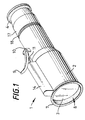
- a portable optical magnifying device As depicted in Figures 1 & 2, a portable optical magnifying device, generally indicated 1, comprises a generally-tapered, semi-telescopic housing 2, fitted at one end with a lens 3 serving as the objective, and at the other end with a lens 4 serving as the eyepiece.
- a suitable optical array essentially (as shown) comprising an aperture 5 and one or more lens(es) 6.
- the optical details of the objective, eyepiece and any intervening optical array are not the direct concern of the present invention, and may be determined as appropriate by those expert in such matters. It is therefore only necessary here to say that the lens train used should be such as to provide a wide-angle objective lens with a field of focus, beyond and thus inside the wall to which the optical device will be attached when in use, deep enough to yield an adequately resolved image throughout at least a major part of the overall thickness of the specimen vessel (e.g. aquarium).
- the specimen vessel e.g. aquarium
- the aperture 5 may advantageously take the form of an adjustable, variable-size iris, which will enable the depth of focus to be adjusted. In such a case means for manual adjustment thereof (not here shown) will be provided externally on the housing 2.
- the eyepiece 4 may be offset, e.g. to be canted upwards, so that it is more conveniently accessible to the eye of the observer.
- the optical array 5,6 within the housing 2 may also include one or more prism(s) (not shown), as appropriate, so as to deflect the light path from the objective towards the offset-eyepiece.
- the objective-end of the tapered housing 2 projects beyond the objective lens 3 and is surrounded by a flexibly-resilient cup-shaped seal 7.
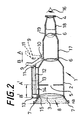
- the space between the objective lens 3 and the seal 7 (when the latter is placed in contact with a flat surface, as indicated by dotted line a in Figure 2, such as an aquarium wall) defines an evacuation chamber, generally indicated 8, therebetween.
- the seal 7 will generally be made in the form of a natural or synthetic rubber gasket ring around the rim of the cup-shaped walls.
- the seal 7 is placed in contact with the flat, transparent surface of a specimen vessel (not shown) such as an aquarium wall, and then the chamber 8 is partially evacuated so as thus to attach the whole optical device in situ on the specimen vessel, so that an observer can now view specimens therewithin.
- Evacuation of the chamber 8 is effected by moving a lever 9 from its rest position B, as shown in dotted lines in Figure 2 to its activated position A.
- the base of lever 9 is hingedly secured to the housing 2 via a pivot-pin 10, about which it can be moved between positions A and B.
- lever 9 is connected via a second pivot-pin 11 to an articulated linkage connected to the end of a piston-rod 12 having a plunger 13 at its opposite end, both mounted within piston-cylinder 13. Movement of the lever 9 between positions B and A causes the rod 12 and plunger 13 to move within piston-cylinder 14, from the plunger's rest position B' to its activated position A'.
- the piston-cylinder 14 communicates with the evacuation chamber 8 via an opening 15 in the rim of the housing 2.
- air is sucked from the evacuation chamber 8, through the opening 15.
- the resultant reduced pressure within evacuation chamber 8 causes the gasket seal ring 7 to flex and seat itself in air-tight contact with the wall of the specimen vessel. It is the partial vacuum suction effect within chamber 8 which effects the temporary attachment of the magnifying device 1 to the specimen vessel.
- An observer may adjust the focus of the device by means of an adjustable cylinder 17 bearing one or more of the lens(es) and/or prism(s) 6 constituting the optical array.
- the cylinder 17 may be rotated within the main housing 2 by means of fine screw threads 18 located on the external surface of the cylinder 17 which co-operate with fine screw threads 19 located on the internal surface of the housing 2, thus adjusting the distance between the lens(es) and/or prism(s) 6 mounted within the cylinder 17, and the remainder of the optical array.
Landscapes
- Physics & Mathematics (AREA)
- General Physics & Mathematics (AREA)
- Optics & Photonics (AREA)
- Chemical & Material Sciences (AREA)
- Analytical Chemistry (AREA)
- Lenses (AREA)
- Microscoopes, Condenser (AREA)
- Telescopes (AREA)
- Eye Examination Apparatus (AREA)
- Glass Compositions (AREA)
- Prostheses (AREA)
- Investigating Or Analysing Materials By The Use Of Chemical Reactions (AREA)
Claims (11)
- Dispositif de grandissement optique portatif (1) pour observer des spécimens à l'intérieur d'un récipient pour spécimens ayant une paroi plate transparente, ce dispositif comprenant :et caractérisé en ce que ledit dispositif (1) comprend en outre :un objectif (3) et un oculaire (4), montés adjacents ou aux extrémités opposées d'un boítier sensiblement tubulaire (2) ;une chambre d'évacuation (8) formée entre l'objectif (3) et une extrémité ouverte dudit boítier tubulaire (2), ladite extrémité ouverte étant munie d'un joint sensiblement étanche à l'air (7) au moins partiellement autour ;des moyens d'évacuation situés extérieurement sur le boítier (2), lesdits moyens d'évacuation comprenant une chambre de piston (14) qui communique avec la chambre d'évacuation (8) via une ouverture (15) dans le boítier (2), et une tête de piston (13) déplaçable à l'intérieur de ladite chambre de piston (14) pour évacuer au moins partiellement ladite chambre d'évacuation (8), pour ainsi permettre au dispositif de grandissement (1) d'être monté par succion de manière détachable à ladite paroi plane.
- Dispositif de grandissement optique portatif (1) selon la revendication 1, dans lequel le boítier (2) est conique télescopiquement et ajustable axialement.
- Dispositif de grandissement optique portatif (1) selon la revendication 1 ou 2, comprenant en outre un ensemble optique comprenant une ouverture (5), une ou plusieurs lentilles (6) et de manière optionnelle un ou plusieurs réflecteurs.
- Dispositif de grandissement optique portatif (1) selon la revendication 3, dans lequel l'ensemble optique comprend en outre un ou plusieurs prismes et/ou autre(s) réflecteur(s).
- Dispositif de grandissement optique portatif (1) selon l'une quelconque des revendications précédentes, dans lequel la tête de piston (13) fonctionne à l'aide d'un levier monté de manière pivotante (9) ménagé extérieurement sur le boítier (2).
- Dispositif de grandissement optique portatif (1) selon l'une quelconque des revendications précédentes, dans lequel :l'objectif (3) est une lentille grand-angle conçue pour des distances de spécimens allant de 7,5 à 90 cm ; et/oul'ouverture (5) prend la forme d'un iris ajustable.
- Dispositif de grandissement optique portatif (1) selon l'une quelconque des revendications précédentes, dans lequel le boítier (2) est construit en sections télescopiques de manière à pouvoir ajuster le foyer du dispositif (1).
- Dispositif de grandissement optique portatif (1) selon l'une quelconque des revendications précédentes, dans lequel le joint sensiblement étanche à l'air (7) est sous la forme d'une bague d'étanchéité en caoutchouc, de préférence en caoutchouc néoprène ou nitrile.
- Dispositif de grandissement optique portatif (1) selon l'une quelconque des revendications précédentes, dans lequel l'oculaire (4) est muni de moyens pour monter un appareil vidéo ou photographique.
- Dispositif de grandissement optique portatif (1) selon l'une quelconque des revendications précédentes, dans lequel le boítier (2) est au moins réalisé de manière prédominante à partir d'aluminium, d'un alliage ou de plusieurs alliages de celui-ci ou de matériaux plastiques, ou de plusieurs de ces éléments.
- Dispositif de grandissement optique portatif (1) selon l'une quelconque des revendications précédentes, dans lequel l'oculaire (4) est incliné d'un angle de sensiblement 45° par rapport à l'axe optique de l'objectif (3).
Applications Claiming Priority (3)
| Application Number | Priority Date | Filing Date | Title |
|---|---|---|---|
| GB0014490A GB2363472A (en) | 2000-06-14 | 2000-06-14 | Portable optical magnifying device which attaches to a flat surface |
| GB0014490 | 2000-06-14 | ||
| PCT/GB2001/002595 WO2001096931A1 (fr) | 2000-06-14 | 2001-06-14 | Dispositif optique, portatif, de grossissement |
Publications (2)
| Publication Number | Publication Date |
|---|---|
| EP1299763A1 EP1299763A1 (fr) | 2003-04-09 |
| EP1299763B1 true EP1299763B1 (fr) | 2004-12-15 |
Family
ID=9893600
Family Applications (1)
| Application Number | Title | Priority Date | Filing Date |
|---|---|---|---|
| EP01940721A Expired - Lifetime EP1299763B1 (fr) | 2000-06-14 | 2001-06-14 | Dispositif optique, portatif, de grossissement |
Country Status (8)
| Country | Link |
|---|---|
| US (1) | US6888673B2 (fr) |
| EP (1) | EP1299763B1 (fr) |
| AT (1) | ATE285083T1 (fr) |
| AU (1) | AU2001274225A1 (fr) |
| DE (1) | DE60107851T2 (fr) |
| ES (1) | ES2233651T3 (fr) |
| GB (1) | GB2363472A (fr) |
| WO (1) | WO2001096931A1 (fr) |
Cited By (1)
| Publication number | Priority date | Publication date | Assignee | Title |
|---|---|---|---|---|
| DE102005046869A1 (de) * | 2005-09-30 | 2007-04-19 | Harald Richter | Gerätehalter-Saugfuß mit Kolben-Zylinder-Anordnung |
Families Citing this family (10)
| Publication number | Priority date | Publication date | Assignee | Title |
|---|---|---|---|---|
| EP1524542B1 (fr) * | 2003-10-17 | 2008-07-02 | Olympus Corporation | Outil d'insertion d'une lentille d'objectif et dispositif de fixation pour un système d'objectif optique |
| WO2006040555A1 (fr) * | 2004-10-12 | 2006-04-20 | Apex Optical Technologies, Ltd. | Dispositif d'observation |
| GB2423825B (en) * | 2005-03-04 | 2009-10-21 | Geoffrey Riddell | A viewer |
| JP4999279B2 (ja) * | 2005-03-09 | 2012-08-15 | スカラ株式会社 | 拡大用アタッチメント |
| DE102010002722B4 (de) * | 2010-03-10 | 2019-06-27 | Leica Microsystems (Schweiz) Ag | Afokales Zoomsystem für ein Mikroskop, Mikroskop mit einem solchen Zoomsystem und Verfahren zum Betreiben eines solchen Zoomsystems |
| CN102789047A (zh) * | 2011-05-17 | 2012-11-21 | 东莞长城光学塑胶厂有限公司 | 一种笔式显微镜的装配方法 |
| KR102065403B1 (ko) * | 2013-04-26 | 2020-01-13 | 엘지전자 주식회사 | 캘리브레이터 |
| USD732592S1 (en) * | 2013-08-12 | 2015-06-23 | Nikon Vision Co., Ltd. | Telescope |
| USD715844S1 (en) | 2013-08-26 | 2014-10-21 | Seneca S. Cooper | Magnifying container |
| US9575311B2 (en) | 2013-11-19 | 2017-02-21 | Seneca S. Cooper | Magnifying container apparatus |
Family Cites Families (11)
| Publication number | Priority date | Publication date | Assignee | Title |
|---|---|---|---|---|
| US2905054A (en) * | 1954-07-07 | 1959-09-22 | Sandy B Logan | Reading glass and mounting |
| US3435532A (en) * | 1965-07-19 | 1969-04-01 | Boeing Co | Optical normalizer |
| JPS4831554B1 (fr) * | 1968-12-24 | 1973-09-29 | ||
| US4356989A (en) * | 1980-06-30 | 1982-11-02 | Ireland Jack W | Resilient suction cup with soft pliable sealing gasket |
| US5062697A (en) * | 1990-08-08 | 1991-11-05 | Mitchell Phillip R | Portable microscope apparatus |
| US5497267A (en) * | 1993-05-21 | 1996-03-05 | Mitsubishi Chemical Corporation | Video microscope |
| JPH0862513A (ja) * | 1994-08-22 | 1996-03-08 | Yamakimi Yanagisawa | レンズ付き環状吸盤 |
| JPH08334540A (ja) * | 1995-06-09 | 1996-12-17 | Jeco Co Ltd | 恒温室内観察用窓およびその形成方法 |
| HUP0003903A1 (en) * | 1995-11-16 | 2000-10-28 | Process for settling down particles floating in liquid and for observing them optically | |
| US6628458B1 (en) * | 1997-07-14 | 2003-09-30 | Brock Optical, Inc. | Microscope with improved camera mount and illumination system |
| JPH11337828A (ja) * | 1998-05-28 | 1999-12-10 | Kisutemu Kk | 水中顕微鏡 |
-
2000
- 2000-06-14 GB GB0014490A patent/GB2363472A/en not_active Withdrawn
-
2001
- 2001-06-14 US US10/311,262 patent/US6888673B2/en not_active Expired - Fee Related
- 2001-06-14 AU AU2001274225A patent/AU2001274225A1/en not_active Abandoned
- 2001-06-14 WO PCT/GB2001/002595 patent/WO2001096931A1/fr not_active Ceased
- 2001-06-14 EP EP01940721A patent/EP1299763B1/fr not_active Expired - Lifetime
- 2001-06-14 DE DE60107851T patent/DE60107851T2/de not_active Expired - Lifetime
- 2001-06-14 ES ES01940721T patent/ES2233651T3/es not_active Expired - Lifetime
- 2001-06-14 AT AT01940721T patent/ATE285083T1/de not_active IP Right Cessation
Cited By (2)
| Publication number | Priority date | Publication date | Assignee | Title |
|---|---|---|---|---|
| DE102005046869A1 (de) * | 2005-09-30 | 2007-04-19 | Harald Richter | Gerätehalter-Saugfuß mit Kolben-Zylinder-Anordnung |
| DE102005046869B4 (de) * | 2005-09-30 | 2008-06-12 | Harald Richter | Gerätehalter-Saugfuß mit Kolben-Zylinder-Anordnung |
Also Published As
| Publication number | Publication date |
|---|---|
| US20030206354A1 (en) | 2003-11-06 |
| EP1299763A1 (fr) | 2003-04-09 |
| GB2363472A (en) | 2001-12-19 |
| DE60107851D1 (de) | 2005-01-20 |
| ATE285083T1 (de) | 2005-01-15 |
| DE60107851T2 (de) | 2005-12-01 |
| US6888673B2 (en) | 2005-05-03 |
| GB0014490D0 (en) | 2000-08-09 |
| AU2001274225A1 (en) | 2001-12-24 |
| WO2001096931A1 (fr) | 2001-12-20 |
| ES2233651T3 (es) | 2005-06-16 |
Similar Documents
| Publication | Publication Date | Title |
|---|---|---|
| EP1299763B1 (fr) | Dispositif optique, portatif, de grossissement | |
| US8624967B2 (en) | Integrated portable in-situ microscope | |
| US8212915B1 (en) | Externally actuable photo-eyepiece relay lens system for focus and photomontage in a wide-field imaging system | |
| KR100842373B1 (ko) | 간이형 영상 확대 장치 | |
| US7869139B2 (en) | Modular afocal variator optical system providing focus with constant magnification | |
| JPH0651245A (ja) | 顕微鏡 | |
| EP3877796B1 (fr) | Kit d'observation microscopique pouvant être associé à un dispositif d'acquisition d'image | |
| US4946257A (en) | Telescope having a removable holding ring assembly | |
| EP4050412A1 (fr) | Dispositif optique a utiliser en macro et stereo photographie | |
| US20160048009A1 (en) | Microscope apparatus and applications thereof | |
| WO2005103792A1 (fr) | Adaptateur optique et dispositif d'imagerie utilisant celui-ci | |
| JP2000284184A (ja) | 平行系実体顕微鏡及び対物レンズ | |
| JP2002519730A (ja) | ハンドスキャナ | |
| WO2020006101A1 (fr) | Système de lentille frontale à immersion | |
| JPS58208720A (ja) | 拡大装置 | |
| US20040228010A1 (en) | Integrated microscopic viewing apparatus | |
| WO2006040555A1 (fr) | Dispositif d'observation | |
| EP4592729A1 (fr) | Indicateur de mise au point réglable pour télescope | |
| CN210051959U (zh) | 一种可调节距离的光学仪器 | |
| CN209962008U (zh) | 手术显微镜集成电子摄像照相装置 | |
| JPH07122690B2 (ja) | 接写装置 | |
| JP2000275544A (ja) | Ccdカメラを使った単レンズ型の顕微鏡観察装置とその付属品 | |
| KR200384479Y1 (ko) | 액정화면 확대장치 | |
| KR20090007619U (ko) | 휴대용 모낭충, 구강세균 현미경 | |
| CN2472247Y (zh) | 一种光学望远镜 |
Legal Events
| Date | Code | Title | Description |
|---|---|---|---|
| PUAI | Public reference made under article 153(3) epc to a published international application that has entered the european phase |
Free format text: ORIGINAL CODE: 0009012 |
|
| AK | Designated contracting states |
Kind code of ref document: A1 Designated state(s): AT BE CH CY DE DK ES FI FR GB GR IE IT LI LU MC NL PT SE TR |
|
| AX | Request for extension of the european patent |
Extension state: AL LT LV MK RO SI |
|
| 17P | Request for examination filed |
Effective date: 20030107 |
|
| 17Q | First examination report despatched |
Effective date: 20030703 |
|
| GRAP | Despatch of communication of intention to grant a patent |
Free format text: ORIGINAL CODE: EPIDOSNIGR1 |
|
| GRAS | Grant fee paid |
Free format text: ORIGINAL CODE: EPIDOSNIGR3 |
|
| GRAA | (expected) grant |
Free format text: ORIGINAL CODE: 0009210 |
|
| AK | Designated contracting states |
Kind code of ref document: B1 Designated state(s): AT BE CH CY DE DK ES FI FR GB GR IE IT LI LU MC NL PT SE TR |
|
| PG25 | Lapsed in a contracting state [announced via postgrant information from national office to epo] |
Ref country code: NL Free format text: LAPSE BECAUSE OF FAILURE TO SUBMIT A TRANSLATION OF THE DESCRIPTION OR TO PAY THE FEE WITHIN THE PRESCRIBED TIME-LIMIT Effective date: 20041215 Ref country code: AT Free format text: LAPSE BECAUSE OF FAILURE TO SUBMIT A TRANSLATION OF THE DESCRIPTION OR TO PAY THE FEE WITHIN THE PRESCRIBED TIME-LIMIT Effective date: 20041215 Ref country code: TR Free format text: LAPSE BECAUSE OF FAILURE TO SUBMIT A TRANSLATION OF THE DESCRIPTION OR TO PAY THE FEE WITHIN THE PRESCRIBED TIME-LIMIT Effective date: 20041215 Ref country code: BE Free format text: LAPSE BECAUSE OF FAILURE TO SUBMIT A TRANSLATION OF THE DESCRIPTION OR TO PAY THE FEE WITHIN THE PRESCRIBED TIME-LIMIT Effective date: 20041215 Ref country code: LI Free format text: LAPSE BECAUSE OF FAILURE TO SUBMIT A TRANSLATION OF THE DESCRIPTION OR TO PAY THE FEE WITHIN THE PRESCRIBED TIME-LIMIT Effective date: 20041215 Ref country code: FI Free format text: LAPSE BECAUSE OF FAILURE TO SUBMIT A TRANSLATION OF THE DESCRIPTION OR TO PAY THE FEE WITHIN THE PRESCRIBED TIME-LIMIT Effective date: 20041215 Ref country code: CH Free format text: LAPSE BECAUSE OF FAILURE TO SUBMIT A TRANSLATION OF THE DESCRIPTION OR TO PAY THE FEE WITHIN THE PRESCRIBED TIME-LIMIT Effective date: 20041215 |
|
| REG | Reference to a national code |
Ref country code: CH Ref legal event code: EP Ref country code: GB Ref legal event code: FG4D |
|
| REG | Reference to a national code |
Ref country code: IE Ref legal event code: FG4D |
|
| REF | Corresponds to: |
Ref document number: 60107851 Country of ref document: DE Date of ref document: 20050120 Kind code of ref document: P |
|
| PG25 | Lapsed in a contracting state [announced via postgrant information from national office to epo] |
Ref country code: GR Free format text: LAPSE BECAUSE OF FAILURE TO SUBMIT A TRANSLATION OF THE DESCRIPTION OR TO PAY THE FEE WITHIN THE PRESCRIBED TIME-LIMIT Effective date: 20050315 Ref country code: DK Free format text: LAPSE BECAUSE OF FAILURE TO SUBMIT A TRANSLATION OF THE DESCRIPTION OR TO PAY THE FEE WITHIN THE PRESCRIBED TIME-LIMIT Effective date: 20050315 Ref country code: SE Free format text: LAPSE BECAUSE OF FAILURE TO SUBMIT A TRANSLATION OF THE DESCRIPTION OR TO PAY THE FEE WITHIN THE PRESCRIBED TIME-LIMIT Effective date: 20050315 |
|
| NLV1 | Nl: lapsed or annulled due to failure to fulfill the requirements of art. 29p and 29m of the patents act | ||
| PG25 | Lapsed in a contracting state [announced via postgrant information from national office to epo] |
Ref country code: IE Free format text: LAPSE BECAUSE OF NON-PAYMENT OF DUE FEES Effective date: 20050614 Ref country code: CY Free format text: LAPSE BECAUSE OF FAILURE TO SUBMIT A TRANSLATION OF THE DESCRIPTION OR TO PAY THE FEE WITHIN THE PRESCRIBED TIME-LIMIT Effective date: 20050614 Ref country code: LU Free format text: LAPSE BECAUSE OF NON-PAYMENT OF DUE FEES Effective date: 20050614 |
|
| REG | Reference to a national code |
Ref country code: ES Ref legal event code: FG2A Ref document number: 2233651 Country of ref document: ES Kind code of ref document: T3 |
|
| PG25 | Lapsed in a contracting state [announced via postgrant information from national office to epo] |
Ref country code: MC Free format text: LAPSE BECAUSE OF NON-PAYMENT OF DUE FEES Effective date: 20050630 |
|
| REG | Reference to a national code |
Ref country code: CH Ref legal event code: PL |
|
| PLBE | No opposition filed within time limit |
Free format text: ORIGINAL CODE: 0009261 |
|
| STAA | Information on the status of an ep patent application or granted ep patent |
Free format text: STATUS: NO OPPOSITION FILED WITHIN TIME LIMIT |
|
| 26N | No opposition filed |
Effective date: 20050916 |
|
| ET | Fr: translation filed | ||
| REG | Reference to a national code |
Ref country code: IE Ref legal event code: MM4A |
|
| PG25 | Lapsed in a contracting state [announced via postgrant information from national office to epo] |
Ref country code: PT Free format text: LAPSE BECAUSE OF NON-PAYMENT OF DUE FEES Effective date: 20050515 |
|
| PGFP | Annual fee paid to national office [announced via postgrant information from national office to epo] |
Ref country code: IT Payment date: 20100608 Year of fee payment: 10 |
|
| PGFP | Annual fee paid to national office [announced via postgrant information from national office to epo] |
Ref country code: ES Payment date: 20100722 Year of fee payment: 10 |
|
| PGFP | Annual fee paid to national office [announced via postgrant information from national office to epo] |
Ref country code: DE Payment date: 20100610 Year of fee payment: 10 Ref country code: FR Payment date: 20100721 Year of fee payment: 10 Ref country code: GB Payment date: 20100401 Year of fee payment: 10 |
|
| GBPC | Gb: european patent ceased through non-payment of renewal fee |
Effective date: 20110614 |
|
| PG25 | Lapsed in a contracting state [announced via postgrant information from national office to epo] |
Ref country code: IT Free format text: LAPSE BECAUSE OF NON-PAYMENT OF DUE FEES Effective date: 20110614 |
|
| REG | Reference to a national code |
Ref country code: FR Ref legal event code: ST Effective date: 20120229 |
|
| REG | Reference to a national code |
Ref country code: DE Ref legal event code: R119 Ref document number: 60107851 Country of ref document: DE Effective date: 20120103 |
|
| PG25 | Lapsed in a contracting state [announced via postgrant information from national office to epo] |
Ref country code: FR Free format text: LAPSE BECAUSE OF NON-PAYMENT OF DUE FEES Effective date: 20110630 Ref country code: DE Free format text: LAPSE BECAUSE OF NON-PAYMENT OF DUE FEES Effective date: 20120103 |
|
| PG25 | Lapsed in a contracting state [announced via postgrant information from national office to epo] |
Ref country code: GB Free format text: LAPSE BECAUSE OF NON-PAYMENT OF DUE FEES Effective date: 20110614 |
|
| REG | Reference to a national code |
Ref country code: ES Ref legal event code: FD2A Effective date: 20130606 |
|
| PG25 | Lapsed in a contracting state [announced via postgrant information from national office to epo] |
Ref country code: ES Free format text: LAPSE BECAUSE OF NON-PAYMENT OF DUE FEES Effective date: 20110615 |