EP1300079A2 - Gargerät mit Feuchtemesseinrichtung und Verfahren zur Feuchtemessung in einem Gargerät - Google Patents
Gargerät mit Feuchtemesseinrichtung und Verfahren zur Feuchtemessung in einem Gargerät Download PDFInfo
- Publication number
- EP1300079A2 EP1300079A2 EP02022196A EP02022196A EP1300079A2 EP 1300079 A2 EP1300079 A2 EP 1300079A2 EP 02022196 A EP02022196 A EP 02022196A EP 02022196 A EP02022196 A EP 02022196A EP 1300079 A2 EP1300079 A2 EP 1300079A2
- Authority
- EP
- European Patent Office
- Prior art keywords
- cooking
- tube
- appliance according
- cooking appliance
- waves
- Prior art date
- Legal status (The legal status is an assumption and is not a legal conclusion. Google has not performed a legal analysis and makes no representation as to the accuracy of the status listed.)
- Granted
Links
- 238000010411 cooking Methods 0.000 title claims abstract description 95
- 238000000034 method Methods 0.000 title claims abstract description 22
- 238000011156 evaluation Methods 0.000 claims description 9
- 239000012528 membrane Substances 0.000 claims description 5
- 230000005284 excitation Effects 0.000 claims description 4
- 230000006870 function Effects 0.000 claims 1
- 230000010355 oscillation Effects 0.000 claims 1
- 239000003570 air Substances 0.000 description 19
- XLYOFNOQVPJJNP-UHFFFAOYSA-N water Chemical compound O XLYOFNOQVPJJNP-UHFFFAOYSA-N 0.000 description 17
- 239000007789 gas Substances 0.000 description 12
- 230000008569 process Effects 0.000 description 12
- 238000012423 maintenance Methods 0.000 description 6
- 238000005259 measurement Methods 0.000 description 6
- 230000008901 benefit Effects 0.000 description 4
- 239000000203 mixture Substances 0.000 description 4
- 230000000875 corresponding effect Effects 0.000 description 3
- 235000013305 food Nutrition 0.000 description 3
- XKRFYHLGVUSROY-UHFFFAOYSA-N Argon Chemical compound [Ar] XKRFYHLGVUSROY-UHFFFAOYSA-N 0.000 description 2
- QVGXLLKOCUKJST-UHFFFAOYSA-N atomic oxygen Chemical compound [O] QVGXLLKOCUKJST-UHFFFAOYSA-N 0.000 description 2
- 230000033228 biological regulation Effects 0.000 description 2
- 238000009529 body temperature measurement Methods 0.000 description 2
- 230000001419 dependent effect Effects 0.000 description 2
- 239000000463 material Substances 0.000 description 2
- 238000000691 measurement method Methods 0.000 description 2
- 239000001301 oxygen Substances 0.000 description 2
- 229910052760 oxygen Inorganic materials 0.000 description 2
- 230000000704 physical effect Effects 0.000 description 2
- IJGRMHOSHXDMSA-UHFFFAOYSA-N Atomic nitrogen Chemical compound N#N IJGRMHOSHXDMSA-UHFFFAOYSA-N 0.000 description 1
- 238000010521 absorption reaction Methods 0.000 description 1
- 239000000443 aerosol Substances 0.000 description 1
- 239000012080 ambient air Substances 0.000 description 1
- 229910052786 argon Inorganic materials 0.000 description 1
- 230000008859 change Effects 0.000 description 1
- 238000004140 cleaning Methods 0.000 description 1
- 239000004020 conductor Substances 0.000 description 1
- 238000007796 conventional method Methods 0.000 description 1
- 230000006378 damage Effects 0.000 description 1
- 238000013016 damping Methods 0.000 description 1
- 230000007423 decrease Effects 0.000 description 1
- 238000001514 detection method Methods 0.000 description 1
- 238000009792 diffusion process Methods 0.000 description 1
- 238000005553 drilling Methods 0.000 description 1
- 230000000694 effects Effects 0.000 description 1
- 230000005670 electromagnetic radiation Effects 0.000 description 1
- 230000006872 improvement Effects 0.000 description 1
- 239000012535 impurity Substances 0.000 description 1
- 239000007788 liquid Substances 0.000 description 1
- 230000007257 malfunction Effects 0.000 description 1
- 238000004519 manufacturing process Methods 0.000 description 1
- 230000003287 optical effect Effects 0.000 description 1
- RVTZCBVAJQQJTK-UHFFFAOYSA-N oxygen(2-);zirconium(4+) Chemical compound [O-2].[O-2].[Zr+4] RVTZCBVAJQQJTK-UHFFFAOYSA-N 0.000 description 1
- 238000002360 preparation method Methods 0.000 description 1
- 230000008439 repair process Effects 0.000 description 1
- 238000012360 testing method Methods 0.000 description 1
- 235000013311 vegetables Nutrition 0.000 description 1
- 229910001928 zirconium oxide Inorganic materials 0.000 description 1
Images

Classifications
-
- A—HUMAN NECESSITIES
- A21—BAKING; EDIBLE DOUGHS
- A21B—BAKERS' OVENS; MACHINES OR EQUIPMENT FOR BAKING
- A21B3/00—Parts or accessories of ovens
- A21B3/04—Air-treatment devices for ovens, e.g. regulating humidity
-
- G—PHYSICS
- G01—MEASURING; TESTING
- G01N—INVESTIGATING OR ANALYSING MATERIALS BY DETERMINING THEIR CHEMICAL OR PHYSICAL PROPERTIES
- G01N29/00—Investigating or analysing materials by the use of ultrasonic, sonic or infrasonic waves; Visualisation of the interior of objects by transmitting ultrasonic or sonic waves through the object
- G01N29/02—Analysing fluids
- G01N29/036—Analysing fluids by measuring frequency or resonance of acoustic waves
-
- G—PHYSICS
- G01—MEASURING; TESTING
- G01N—INVESTIGATING OR ANALYSING MATERIALS BY DETERMINING THEIR CHEMICAL OR PHYSICAL PROPERTIES
- G01N2291/00—Indexing codes associated with group G01N29/00
- G01N2291/01—Indexing codes associated with the measuring variable
- G01N2291/014—Resonance or resonant frequency
-
- G—PHYSICS
- G01—MEASURING; TESTING
- G01N—INVESTIGATING OR ANALYSING MATERIALS BY DETERMINING THEIR CHEMICAL OR PHYSICAL PROPERTIES
- G01N2291/00—Indexing codes associated with group G01N29/00
- G01N2291/02—Indexing codes associated with the analysed material
- G01N2291/028—Material parameters
- G01N2291/02818—Density, viscosity
-
- G—PHYSICS
- G01—MEASURING; TESTING
- G01N—INVESTIGATING OR ANALYSING MATERIALS BY DETERMINING THEIR CHEMICAL OR PHYSICAL PROPERTIES
- G01N2291/00—Indexing codes associated with group G01N29/00
- G01N2291/02—Indexing codes associated with the analysed material
- G01N2291/028—Material parameters
- G01N2291/02845—Humidity, wetness
-
- G—PHYSICS
- G01—MEASURING; TESTING
- G01N—INVESTIGATING OR ANALYSING MATERIALS BY DETERMINING THEIR CHEMICAL OR PHYSICAL PROPERTIES
- G01N2291/00—Indexing codes associated with group G01N29/00
- G01N2291/02—Indexing codes associated with the analysed material
- G01N2291/028—Material parameters
- G01N2291/02881—Temperature
-
- G—PHYSICS
- G01—MEASURING; TESTING
- G01N—INVESTIGATING OR ANALYSING MATERIALS BY DETERMINING THEIR CHEMICAL OR PHYSICAL PROPERTIES
- G01N2291/00—Indexing codes associated with group G01N29/00
- G01N2291/04—Wave modes and trajectories
- G01N2291/042—Wave modes
- G01N2291/0421—Longitudinal waves
Definitions
- the invention relates to a cooking device with a cooking space with a cooking atmosphere, with a temperature measuring device for determining the temperature of the cooking atmosphere, with a device for generating acoustic waves, with a Tube in which the device for generating acoustic waves is arranged, and with an evaluation unit, the tube and the device for production acoustic waves Part of a device for determining moisture the cooking atmosphere in the cooking space and the speed of sound in the cooking chamber in the evaluation unit to determine the humidity becomes.
- It also relates to a method for determining the moisture in the cooking atmosphere in a cooking chamber of a cooking appliance, in which the temperature the cooking atmosphere is determined, with the acoustic waves in a tube generated and at which the speed of sound in the cooking space for determination the humidity is used.
- US Pat. No. 5,689,062 proposes as a further improvement, in one Cooking device for determining the humidity in microwave ovens in the area below 100 ° C to use the speed of sound. It will be hollow in two Measuring tube generates sound waves. Both tubes are arranged in the cooking space and have sleeves made of thermally highly conductive material. One of the tubes is sealed airtight, the other is in the cooking chamber with the atmosphere and therefore has approximately the same humidity as this on. A conclusion can then be drawn from the phase difference of the sound waves the moisture in the cooking space is drawn.
- This measurement method takes into account that below 100 ° C saturation limits for water vapor cannot be exceeded, so that only slight and approximately linear changes The speed of sound can occur, resulting in a shift from a few to a maximum of about 40 to 50 ° of the phase angle of a sound wave can impact. For higher temperatures and other than microwave ovens this arrangement is not suitable.
- acoustic standing waves are generated in the tube by resonance excitation
- a device is provided which measures the frequency of the device for generating acoustic waves generated waves so that acoustic standing waves arise, and that the set by the device Frequency and the data of the temperature measuring device of the evaluation unit are supplied and the moisture is determined therefrom.
- the tube is excited by resonance excitation acoustic standing waves are generated that the frequency of the generated acoustic waves is set so that the maxima of the standing Waves are maintained and that the set frequency and the temperature is evaluated and the moisture is determined therefrom.
- a control loop can be built around which Control the water vapor content in the cooking space according to a setpoint.
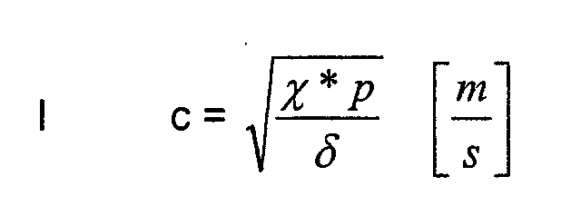
- the speed of sound of a medium depends on its density. you conversely, the density of a Determine gas or a gas mixture. By means of a sound velocity measurement you can see the density of the cooking atmosphere during the cooking process determine and from this the proportion of water vapor and thus the Determine the humidity of the cooking atmosphere.
- This application takes into account that the different cooking temperature (typically between 100 ° C and 300 ° C) also changes the density of the cooking atmosphere. Therefore, too the temperature measurement already present in every cooking appliance during the procedure also used, which accordingly does not lead to additional equipment expenditure leads.
- the speed of sound is not determined as in U.S. Patent 5,689,062 by comparing the phase difference of two Sound waves in different media or through transit time measurements, but by creating a standing wave in a tube.
- the resonance frequency is related to the wavelength and the Wavelength fixed by the length of the tube and therefore constant changes in humidity and / or temperature change the resonance frequency.
- the temperature is advantageously one that is already present Temperature measurement or with a special temperature measuring device determined and additionally used in the determination of the moisture.
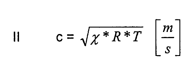
- ⁇ is the material-dependent adiabatic exponent C p / C v and assumes the value 1.4 for air in the typical composition of N 2 , O 2 and Ar.
- the left side of the equation corresponds to the mass ratio of water vapor to dry air, which is also an indication of the humidity or humidity of the air.
- the parameters R dry air and R water vapor are known and R atmosphere is obtained from the measurement of the speed of sound c and used in Equation III.
- this boundary condition also becomes still considered. This happens because of an iteration process ⁇ is determined more precisely.
- the moisture content is assumed calculated from ⁇ and calculated a new ⁇ based on the result (linear interpolation between 1.33 and 1.4 depending on the calculated water vapor content). If the calculated value of ⁇ no longer changes (accuracy limit ), the iteration is ended.
- an embodiment of the invention is used for this purpose which a device for feedback is provided.
- a high pass filter can now filter out all annoying noises caused by the movement of the fan wheel etc. arise and the feedback is disruptive can influence.
- a bandpass filter that comes from the feedback Frequencies only desired frequency ranges, especially outside the human hearing range, can also undesirable overtones be filtered away.
- a so-called tracking filter is particularly suitable, too Called tracking filter, which spans around a frequency in the filter and at variable center frequency "follows", that is, the frequency range currently adapts.
- the standing one is preferably at the position of a vibration node Shafts in the tube arranged at least one hole in the tube wall. Especially it is preferred to enforce the above-mentioned upper modes at least at the position of two vibration nodes of the standing waves arrange at least one hole in the pipe wall in the pipe.
- the moisture determination can not only be used tends to add or stop adding water to the To influence the cooking atmosphere to adjust the humidity. It can even intervene very precisely in the sequence and control of the cooking processes, to run fully automatic processes, for example, from new variable products with different moisture contents (vegetables different Origin) to optimally cook specified dishes.
- FIG. 1 shows a schematic structure of an exemplary embodiment of a cooking device according to the invention .
- a housing 10 contains a cooking chamber 11 which is filled with a cooking atmosphere during the cooking process.
- This cooking atmosphere primarily consists of the proportions of nitrogen (N 2 ), oxygen (O 2 ) and argon (Ar) that are typical for air and are essentially constant in relation to each other and a fluctuating one that is influenced by the cooking process and the food and is of particular interest here Proportion of water vapor (H 2 O).
- the cooking space is accessible from the outside through a door area 12, which is also a Window can have that for the user an optical tracking of the Allows progress of the cooking process.
- the measurement values that is to say the temperature T and the quantities determined by the moisture measuring device 30 are linked to the known fixed quantities such as the material constants already discussed above.
- the result can then be used to control the device control.
- a corresponding actuator is actuated to over to regulate an actual / target comparison according to the target value specification.
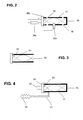
- FIG. 2 shows a schematic representation of an embodiment of a device for determining the moisture for an inventive cooking device in an enlarged representation.
- the device 30 has a tube 31.
- the tube 31 is particularly equipped with a device 32 for generating acoustic waves.
- the tube 31 is approximately cylindrical and has an approximately cylindrical Pipe wall. At the two opposite ends 33 and 34 in this embodiment the tube is closed.
- the device 32 for Generation of the acoustic waves is located adjacent to one end 33.
- the membrane 35 b of the device 32 for generating acoustic Shut off the entire surface of the tube 31 at this end 33.
- the membrane 35 b the closed end 33 in the mechanical Form senses.
- This embodiment is especially for a highly turbulent cooking chamber atmosphere provided, because only through the holes an exchange with the cooking chamber atmosphere he follows.
- the number, size and location of the holes can vary from depending on the strength of the surrounding turbulence.
- the diameter of the tube 31 should be less than half the wavelength a standing wave. This prevents cross vibrations in the pipe arise. Only longitudinal waves in the longitudinal direction can be in this Train the trap.
- the length of the tube can be exactly half the wavelength, ie ⁇ / 2.
- the atmosphere in tube 31 vibrates at the fundamental frequency.
- the easiest way to excite the resonance is at the fundamental frequency.
- Prefers is however a vibration in higher modes, such as in the third or fourth upper mode. This shifts the frequency to a range above 20 kHz, i.e. out of the human hearing range. Even higher fashions are possible, but offer no further advantages.
- this is done by feedback.
- an alternating pressure receiver 35a for example a condenser microphone, in the tube to be ordered.
- the condenser microphone is arranged in a Position that corresponds to an antinode in the standing wave.
- This Alternating pressure receiver 35a can now be maintained by means of feedback the resonance vibration can be used.
- regulation can be provided that is constant tracks the frequency so that the maximum possible vibration amplitude is obtained remains.
- This increasing voltage drop can be at a series resistor 35c in the supply circuit observed the device 32 for generating acoustic waves and can be used to readjust the voltage-controlled oscillator. This Readjustment is carried out until the current or the voltage drop the series resistor 35c has in turn reached its minimum. As a result of this Regulation changes the frequency, which as discussed for determining Humidity and temperature is used.
- FIG. 31 An alternative embodiment of a tube 31 is shown in FIG .
- This alternative embodiment is suitable for a low-turbulence environment and can be arranged, for example, in an area which is still connected to the cooking chamber atmosphere, but is flow-shielded from it.
- the tube 31 is closed at one end 33, but open at the other end 34.
- the length of the tube is an integer multiple of (2n-1) x / 4.
- the open end 34 of the tube can be used directly here in order to enable the exchange with the cooking space atmosphere by diffusion. It is therefore possible to dispense with bores 36 if only the fundamental vibration is to be used.
- FIG. 4 finally shows a further possibility which can be used in combination with one of the two tubes 31 from FIGS. 2 or 3.
- FIG. 4 shows a further tube 51, which is otherwise very similar, which is equipped with a device 52 for generating acoustic waves and is closed at both ends 53, 54 and has no bores for gas exchange with the surroundings.
- This tube 51 is filled with dry air, so it has constant humidity. To avoid an increase in pressure inside, it is connected via a capillary tube 57 to an expansion tank 58, preferably a resilient rubber ball.
- the temperature is measured here as a frequency-dependent variable. If the temperatures in the two tubes 31, 51 are identical, then directly the value of the resonance frequency in the second tube 51 with respect to the resonance frequency placed in the first tube 31 and concluded from the moisture become.
- thermo measuring device 23 including the device 32 for generating acoustic Completely gas-tight waves, so no destruction of the speaker diaphragm 35b occur as a result of a temperature-related pressure increase can.
Landscapes
- Physics & Mathematics (AREA)
- Life Sciences & Earth Sciences (AREA)
- Biochemistry (AREA)
- General Health & Medical Sciences (AREA)
- Acoustics & Sound (AREA)
- Health & Medical Sciences (AREA)
- Chemical & Material Sciences (AREA)
- Analytical Chemistry (AREA)
- Engineering & Computer Science (AREA)
- Food Science & Technology (AREA)
- General Physics & Mathematics (AREA)
- Immunology (AREA)
- Pathology (AREA)
- Investigating Or Analyzing Materials By The Use Of Ultrasonic Waves (AREA)
- Electric Ovens (AREA)
- Investigating Or Analyzing Materials Using Thermal Means (AREA)
Abstract
Description

- Figur 1
- eine schematische Darstellung eines erfindungsgemäßen Gerätes;
- Figur 2
- eine schematische Darstellung einer Ausführungsform einer Einrichtung zur Bestimmung der Feuchte für ein erfindungsgemäßes Gargerät;
- Figur 3
- eine schematische Darstellung einer anderen Ausführungsform einer Einrichtung zur Bestimmung der Feuchte für ein erfindungsgemäßes Gargerät; und
- Figur 4
- eine schematische Darstellung einer Ausführungsform für eine Vergleichsmessung zur Unterstützung der Einrichtung zur Bestimmung der Feuchte.
- 10
- Gehäuse
- 11
- Garraum
- 12
- Türbereich
- 20
- Heizkörper
- 21
- Gargutträgerblech
- 22
- Lüfterrad
- 23
- Temperaturmesseinrichtung
- 25
- Luftleitblech
- 30
- Einrichtung zur Bestimmung der Feuchte beziehungsweise Feuchtemesseinrichtung
- 31
- Rohr
- 32
- Einrichtung zur Erzeugung akustischer Wellen
- 33
- Ende des Rohres
- 34
- Ende des Rohres
- 35
- Vorrichtung zur Einstellung der Frequenz
- 35a
- Wechseldruckempfänger
- 35b
- Membran
- 35c
- Vorwiderstand
- 36
- Bohrungen
- 40
- Auswertungseinheit beziehungsweise elektronische Schaltung
- 41
- Gerätesteuerung
- 51
- Rohr
- 52
- Einrichtung zur Erzeugung akustischer Wellen
- 53
- Ende des Rohres
- 54
- Ende des Rohres
- 57
- Kapillarröhrchen
- 58
- Ausgleichsbehälter
Claims (20)
- Gargerätdadurch gekennzeichnet, dass in dem Rohr (31) durch Resonanzanregung akustische stehende Wellen erzeugt werden,mit einem Garraum (11) mit einer Garatmosphäre,mit einer Temperaturmesseinrichtung (23) zur Bestimmung der Temperatur der Garatmosphäre,mit einer Einrichtung (32) zur Erzeugung akustischer Wellen,mit einem Rohr (31), in dem die Einrichtung (32) zur Erzeugung akustischer Wellen angeordnet ist, undmit einer Auswertungseinheit (40),wobei das Rohr (31) und die Einrichtung (32) zur Erzeugung akustischer Wellen Teil einer Einrichtung (30) zur Bestimmung der Feuchte der Garatmosphäre in dem Garraum (11) sind und wobei die Schallgeschwindigkeit in dem Garraum (11) in der Auswertungseinheit (40) zur Bestimmung der Feuchte herangezogen wird,
dass eine Vorrichtung (35) vorgesehen ist, die die Frequenz der von der Einrichtung (32) zur Erzeugung akustischer Wellen erzeugten Wellen so einstellt, dass akustische stehende Wellen entstehen, und
dass die von der Vorrichtung (35) eingestellte Frequenz und die Daten der Temperaturmesseinrichtung (23) der Auswertungseinheit (40) zugeführt werden und daraus die Feuchte ermittelt wird. - Gargerät nach Anspruch 1,
dadurch gekennzeichnet, dass die Vorrichtung (35) eine Rückkopplungsvorrichtung ist, die die Einstellung der Frequenz der von der Einrichtung (32) zur Erzeugung akustischer Wellen erzeugten Wellen durch Rückkopplung vornimmt. - Gargerät nach Anspruch 2
dadurch gekennzeichnet, dass die Vorrichtung (35) einen Wechseldruckempfänger aufweist, der im Rohr (31) an der Position eines Schwingungsbauches der stehenden Wellen angeordnet ist, und
dass der Wechseldruckempfänger eine Rückkopplung auf die Einrichtung zur Erzeugung der akustischen Welle (32) abgibt. - Gargerät nach Anspruch 2 oder 3,
dadurch gekennzeichnet, dass die Vorrichtung (35) ein Hochpassfilter oder ein Bandpassfilter oder einen Mitlauffilter aufweist, das aus den rückgekoppelten Frequenzen nur gewünschte Frequenzbereiche, insbesondere außerhalb und oberhalb des menschlichen Hörbereiches, zulässt. - Gargerät nach einem der vorstehenden Ansprüche,
dadurch gekennzeichnet, dass an der Position eines Schwingungsknotens der stehenden Wellen im Rohr (31) mindestens eine Bohrung (36) in der Rohrwandung angeordnet ist. - Gargerät nach Anspruch 5,
dadurch gekennzeichnet, dass mindestens an der Position von zwei Schwingungsknoten der stehenden Wellen im Rohr (31) mindestens je eine Bohrung (36) in der Rohrwandung angeordnet ist. - Gargerät nach Anspruch 5 oder 6,
dadurch gekennzeichnet, dass die Bohrungen (36) als Schlitze ausgebildet sind. - Gargerät nach Anspruch 7,
dadurch gekennzeichnet, dass die Bohrung (36) als das Rohr (31) in mehrere Rohrelemente trennender Schlitz ausgebildet ist. - Gargerät nach Anspruch 5 oder 6,
dadurch gekennzeichnet, dass die Bohrungen einen kreisförmigen Querschnitt besitzen. - Gargerät nach einem der vorstehenden Ansprüche,
dadurch gekennzeichnet, dass die Vorrichtung (35) eine Nachführvorrichtung ist, die die Einstellung der Frequenz der von der Einrichtung (32) zur Erzeugung akustischer Wellen erzeugten Wellen in Abhängigkeit von veränderlichen Messwerten vornimmt. - Gargerät nach Anspruch 10,
dadurch gekennzeichnet, dass die Vorrichtung (35) ein Filter aufweist, das aus den nachgeführten Frequenzen nur gewünschte Frequenzbereiche, insbesondere außerhalb und oberhalb des menschlichen Hörbereiches, zulässt. - Gargerät nach Anspruch 10 oder 11,
dadurch gekennzeichnet, dass der Hub einer Membran (35b) der Einrichtung (32) zur Erzeugung akustischer Wellen für eine Regelung auf maximale Schwingungsamplitude herangezogen wird. - Gargerät nach Anspruch 10 oder 11,
dadurch gekennzeichnet, dass ein spannungsgesteuerter Oszillator (voltage controlled Oscillator, VCO) vorgesehen ist, der einen Spannungsabfall an einem Widerstand im Speisestromkreis der Einrichtung für die Erzeugung der akustischen Wellen (32) zur Regelung der Frequenz verwendet. - Gargerät nach einem der vorstehenden Ansprüche,
dadurch gekennzeichnet, dass die Abmessungen des Rohres (31) und die von der Einrichtung (32) zur Erzeugung akustischer Wellen erzeugten Wellen so aufeinander abgestimmt sind, dass eine stehende Welle in einem Obermodus, insbesondere im dritten oder vierten Obermodus entsteht. - Gargerät nach einem der vorstehenden Ansprüche,
dadurch gekennzeichnet, dass die Temperaturmesseinrichtung (23) ein Rohr (51) aufweist, das wie das erste Rohr (31) aufgebaut ist,
dass an beiden Enden (53, 54) geschlossen ist und keine Bohrungen (36) aufweist, und
dass zum Druckausgleich ein Kapillarröhrchen (57) besitzt, das zu einem Ausgleichsbehälter (58) führt. - Gargerät nach einem der vorstehenden Ansprüche,
dadurch gekennzeichnet, dass die Temperaturmesseinrichtung (23) ein vollkommen gasdichtes Gehäuse aufweist, das die Einrichtung (52) zur Erzeugung akustischer Wellen einschließt. - Gargerät nach Anspruch 15 oder 16,
dadurch gekennzeichnet, dass der Messwert der Feuchte aus der Differenzfrequenz der akustischen Wellen in den Rohren (31, 51) ermittelt wird. - Verfahren zur Bestimmung der Feuchte in der Garatmosphäre in einem Garraum (11) eines Gargerätes,
bei dem die Temperatur der Garatmosphäre bestimmt wird,
bei dem akustische Wellen in einem Rohr (31) erzeugt werden, und
bei dem die Schallgeschwindigkeit in dem Garraum (11) zur Bestimmung der Feuchte herangezogen wird,
dadurch gekennzeichnet, dass in dem Rohr (31) durch Resonanzanregung akustische stehende Wellen erzeugt werden,
dass die Frequenz der erzeugten akustischen Wellen so eingestellt wird, dass die Maxima der stehenden Wellen aufrecht erhalten bleiben und dass die dabei eingestellte Frequenz und die Temperatur ausgewertet und daraus die Feuchte ermittelt wird. - Verfahren nach Anspruch 18,
dadurch gekennzeichnet, dass die Frequenz der erzeugten akustischen Wellen durch Rückkopplung eingestellt wird. - Verfahren nach Anspruch 18,
dadurch gekennzeichnet, dass die Frequenz der erzeugten akustischen Wellen durch Nachführung eingestellt wird.
Applications Claiming Priority (2)
| Application Number | Priority Date | Filing Date | Title |
|---|---|---|---|
| DE10148709 | 2001-10-06 | ||
| DE10148709 | 2001-10-06 |
Publications (3)
| Publication Number | Publication Date |
|---|---|
| EP1300079A2 true EP1300079A2 (de) | 2003-04-09 |
| EP1300079A3 EP1300079A3 (de) | 2005-04-27 |
| EP1300079B1 EP1300079B1 (de) | 2007-06-27 |
Family
ID=7701196
Family Applications (1)
| Application Number | Title | Priority Date | Filing Date |
|---|---|---|---|
| EP02022196A Expired - Lifetime EP1300079B1 (de) | 2001-10-06 | 2002-10-04 | Gargerät mit Feuchtemesseinrichtung und Verfahren zur Feuchtemessung in einem Gargerät |
Country Status (3)
| Country | Link |
|---|---|
| EP (1) | EP1300079B1 (de) |
| AT (1) | ATE365456T1 (de) |
| DE (1) | DE50210369D1 (de) |
Cited By (5)
| Publication number | Priority date | Publication date | Assignee | Title |
|---|---|---|---|---|
| EP1837600A3 (de) * | 2006-03-24 | 2009-01-28 | E.G.O. ELEKTRO-GERÄTEBAU GmbH | Verfahren zur Überwachung bzw. Steuerung oder Regelung eines geschlossenen Elektrowärmegerätes |
| EP2469174A3 (de) * | 2010-12-22 | 2014-07-02 | Miele & Cie. KG | Gargerät |
| DE102016112683A1 (de) * | 2016-07-11 | 2018-01-11 | Rational Aktiengesellschaft | Verfahren zur Bestimmung der Feuchtigkeit innerhalb eines Garraumes eines Gargeräts sowie Gargerät |
| DE102019119071A1 (de) * | 2019-07-15 | 2021-01-07 | Miele & Cie. Kg | Verfahren zum Betreiben eines Geräts, insbesondere Gargerät oder Trocknungsgerät, und Gerät |
| CN115145333A (zh) * | 2022-07-26 | 2022-10-04 | 珠海格力电器股份有限公司 | 烹饪设备的调试方法、调试装置、处理器与调试系统 |
Families Citing this family (2)
| Publication number | Priority date | Publication date | Assignee | Title |
|---|---|---|---|---|
| DE102008024021B4 (de) | 2008-05-16 | 2010-02-11 | Rational Ag | Verfahren zur Feuchtemessung, Kondensationsdruckkammer hierfür und Gargerät hiermit |
| DE102016112680B4 (de) * | 2016-07-11 | 2025-03-27 | Rational Aktiengesellschaft | Gargerät |
Citations (7)
| Publication number | Priority date | Publication date | Assignee | Title |
|---|---|---|---|---|
| DE4141768A1 (de) | 1991-12-18 | 1993-06-24 | Miele & Cie | Kochherd, insbesondere mikrowellenherd |
| EP0386862B1 (de) | 1989-03-09 | 1994-07-13 | LechMetall Landsberg GmbH Edelstahlerzeugnisse | Gargerät |
| EP0517433B1 (de) | 1991-05-28 | 1994-09-21 | Kabushiki Kaisha Toshiba | Heizapparat |
| DE4206845C2 (de) | 1992-03-04 | 1997-10-23 | Rational Gmbh | Vorrichtung zum Bestimmen des Anteils einer Gaskomponente in einem Gasgemisch sowie Verwendung der Vorrichtung |
| US5689062A (en) | 1996-01-11 | 1997-11-18 | University Of Kentucky Research Foundation | Method of assessing tool-life in grooved tools |
| EP0701388B1 (de) | 1994-09-09 | 2000-09-20 | ELECTROLUX ZANUSSI GRANDI IMPIANTI S.p.A. | Kochofen ausgestattet mit einem verbesserten Feuchtigkeitssensor |
| DE20013489U1 (de) | 2000-08-04 | 2001-01-18 | Flick, Gernot, Dipl.-Ing., 65205 Wiesbaden | Messung des Wasserdampfgehaltes im Garraum eines Umluftofens |
Family Cites Families (2)
| Publication number | Priority date | Publication date | Assignee | Title |
|---|---|---|---|---|
| DE906023C (de) * | 1948-10-02 | 1954-04-05 | Norbert Kurt Endell Dipl Ing | Einrichtung zur Messung des Feuchtigkeitsgehalts von Gasen |
| US5689060A (en) * | 1992-03-06 | 1997-11-18 | Matsushita Electric Industrial Co., Ltd. | Humidity measuring device and a heat cooker employing the device |
-
2002
- 2002-10-04 DE DE50210369T patent/DE50210369D1/de not_active Expired - Lifetime
- 2002-10-04 EP EP02022196A patent/EP1300079B1/de not_active Expired - Lifetime
- 2002-10-04 AT AT02022196T patent/ATE365456T1/de not_active IP Right Cessation
Patent Citations (7)
| Publication number | Priority date | Publication date | Assignee | Title |
|---|---|---|---|---|
| EP0386862B1 (de) | 1989-03-09 | 1994-07-13 | LechMetall Landsberg GmbH Edelstahlerzeugnisse | Gargerät |
| EP0517433B1 (de) | 1991-05-28 | 1994-09-21 | Kabushiki Kaisha Toshiba | Heizapparat |
| DE4141768A1 (de) | 1991-12-18 | 1993-06-24 | Miele & Cie | Kochherd, insbesondere mikrowellenherd |
| DE4206845C2 (de) | 1992-03-04 | 1997-10-23 | Rational Gmbh | Vorrichtung zum Bestimmen des Anteils einer Gaskomponente in einem Gasgemisch sowie Verwendung der Vorrichtung |
| EP0701388B1 (de) | 1994-09-09 | 2000-09-20 | ELECTROLUX ZANUSSI GRANDI IMPIANTI S.p.A. | Kochofen ausgestattet mit einem verbesserten Feuchtigkeitssensor |
| US5689062A (en) | 1996-01-11 | 1997-11-18 | University Of Kentucky Research Foundation | Method of assessing tool-life in grooved tools |
| DE20013489U1 (de) | 2000-08-04 | 2001-01-18 | Flick, Gernot, Dipl.-Ing., 65205 Wiesbaden | Messung des Wasserdampfgehaltes im Garraum eines Umluftofens |
Cited By (8)
| Publication number | Priority date | Publication date | Assignee | Title |
|---|---|---|---|---|
| EP1837600A3 (de) * | 2006-03-24 | 2009-01-28 | E.G.O. ELEKTRO-GERÄTEBAU GmbH | Verfahren zur Überwachung bzw. Steuerung oder Regelung eines geschlossenen Elektrowärmegerätes |
| EP2469174A3 (de) * | 2010-12-22 | 2014-07-02 | Miele & Cie. KG | Gargerät |
| DE102016112683A1 (de) * | 2016-07-11 | 2018-01-11 | Rational Aktiengesellschaft | Verfahren zur Bestimmung der Feuchtigkeit innerhalb eines Garraumes eines Gargeräts sowie Gargerät |
| WO2018011210A1 (de) * | 2016-07-11 | 2018-01-18 | Rational Aktiengesellschaft | Verfahren zur bestimmung der feuchtigkeit innerhalb eines garraumes eines gargeräts sowie gargerät |
| US11193911B2 (en) * | 2016-07-11 | 2021-12-07 | Rational Aktiengesellschaft | Method for determining the moisture content within a cooking chamber of a cooking device, and cooking device |
| DE102016112683B4 (de) * | 2016-07-11 | 2025-08-21 | Rational Aktiengesellschaft | Verfahren zur Bestimmung der Feuchtigkeit innerhalb eines Garraumes eines Gargeräts sowie Gargerät |
| DE102019119071A1 (de) * | 2019-07-15 | 2021-01-07 | Miele & Cie. Kg | Verfahren zum Betreiben eines Geräts, insbesondere Gargerät oder Trocknungsgerät, und Gerät |
| CN115145333A (zh) * | 2022-07-26 | 2022-10-04 | 珠海格力电器股份有限公司 | 烹饪设备的调试方法、调试装置、处理器与调试系统 |
Also Published As
| Publication number | Publication date |
|---|---|
| EP1300079A3 (de) | 2005-04-27 |
| ATE365456T1 (de) | 2007-07-15 |
| DE50210369D1 (de) | 2007-08-09 |
| EP1300079B1 (de) | 2007-06-27 |
Similar Documents
| Publication | Publication Date | Title |
|---|---|---|
| DE69222052T2 (de) | Sensor für verschiedene gaseigenschaften | |
| WO2008101843A1 (de) | VERFAHREN ZUR BESTIMMUNG UND/ODER ÜBERWACHUNG EINER PROZESSGRÖßE EINES MEDIUMS UND ENTSPRECHENDE VORRICHTUNG | |
| WO2008009522A1 (de) | VORRICHTUNG ZUR BESTIMMUNG UND/ODER ÜBERWACHUNG EINER PROZESSGRÖßE EINES MEDIUMS | |
| DE10050299A1 (de) | Vorrichtung zur Bestimmung und/oder Überwachung der Viskosität eines Mediums in einem Behälter | |
| EP2564174B1 (de) | VORRICHTUNG ZUR BESTIMMUNG UND/ODER ÜBERWACHUNG EINER PROZESSGRÖßE EINES MEDIUMS | |
| EP1300079B1 (de) | Gargerät mit Feuchtemesseinrichtung und Verfahren zur Feuchtemessung in einem Gargerät | |
| DE102004063228A1 (de) | Meßvorrichtung und -verfahren zur Bestimmung einer dielektrischen Eigenschaft, insbesondere der Feuchte und/oder Dichte, eines Produkts | |
| DE2454788A1 (de) | Verfahren und vorrichtung zur feuchtigkeitsbestimmung eines gasfoermigen mediums | |
| EP3521774B1 (de) | Ultraschall-durchflussmessvorrichtung und verfahren zum bestimmen der strömungsgeschwindigkeit | |
| DE102010034428B3 (de) | Vorrichtung und System zur selektiven Detektion von Gaskomponenten oder von Konzentrationen von Gaskomponente in einem zu untersuchendem Gas und Verfahren zum Betrieb einer derartigen Vorrichtung | |
| EP2952874A1 (de) | Verfsahren zur ermittlung eines dichtewertes | |
| DE102004045199A1 (de) | Messvorrichtung und Verfahren zur Bestimmung von Temperatur und/oder Druck und Verwendung der Messvorrichtung | |
| DE102005025671B3 (de) | Verfahren und Vorrichtung zur Messung der spezifischen Dichte eines gasförmigen oder flüssigen Mediums | |
| EP3481204B1 (de) | Verfahren zur bestimmung der feuchtigkeit innerhalb eines garraumes eines gargeräts sowie gargerät | |
| WO2014016110A1 (de) | Verfahren zur ermittlung einer blasengrössenverteilung und messeinrichtung | |
| DE10143841B4 (de) | Gargerät mit Feuchtemesseinrichtung | |
| EP3079444A1 (de) | Verfahren zum betrieb eines kochfeldes sowie ein kochfeld | |
| EP3246479B1 (de) | Absorbereinheit zum absorbieren von schall | |
| DE102016112679A1 (de) | Verfahren und Anordnung zur Analyse von Gaseigenschaften | |
| AT518284B1 (de) | Verfahren zur Analyse von Komponenten eines Messgases | |
| DE102005035085B4 (de) | Verfahren zur Einstellung der akustischen Eigenschaften einer Brennkammer | |
| DE102016112678A1 (de) | Verfahren und Anordnung zur Analyse von Gaseigenschaften | |
| DE102006053277B4 (de) | Resonatorvorrichtung und Brennkammervorrichtung | |
| DE102016112680B4 (de) | Gargerät | |
| DE102024136969B3 (de) | System und Verfahren zur Herstellung von Blasen und/oder Tropfen mittels einer Düse |
Legal Events
| Date | Code | Title | Description |
|---|---|---|---|
| PUAI | Public reference made under article 153(3) epc to a published international application that has entered the european phase |
Free format text: ORIGINAL CODE: 0009012 |
|
| AK | Designated contracting states |
Designated state(s): AT BE BG CH CY CZ DE DK EE ES FI FR GB GR IE IT LI LU MC NL PT SE SK TR Kind code of ref document: A2 Designated state(s): AT BE BG CH CY CZ DE DK EE ES FI FR GB GR IE IT LI LU MC NL PT SE SK TR |
|
| AX | Request for extension of the european patent |
Extension state: AL LT LV MK RO SI |
|
| PUAL | Search report despatched |
Free format text: ORIGINAL CODE: 0009013 |
|
| AK | Designated contracting states |
Kind code of ref document: A3 Designated state(s): AT BE BG CH CY CZ DE DK EE ES FI FR GB GR IE IT LI LU MC NL PT SE SK TR |
|
| AX | Request for extension of the european patent |
Extension state: AL LT LV MK RO SI |
|
| 17P | Request for examination filed |
Effective date: 20051021 |
|
| AKX | Designation fees paid |
Designated state(s): AT BE BG CH CY CZ DE DK EE ES FI FR GB GR IE IT LI LU MC NL PT SE SK TR |
|
| GRAP | Despatch of communication of intention to grant a patent |
Free format text: ORIGINAL CODE: EPIDOSNIGR1 |
|
| GRAS | Grant fee paid |
Free format text: ORIGINAL CODE: EPIDOSNIGR3 |
|
| GRAA | (expected) grant |
Free format text: ORIGINAL CODE: 0009210 |
|
| RAP1 | Party data changed (applicant data changed or rights of an application transferred) |
Owner name: MKN MASCHINENFABRIK KURT NEUBAUER GMBH & CO. |
|
| AK | Designated contracting states |
Kind code of ref document: B1 Designated state(s): AT BE BG CH CY CZ DE DK EE ES FI FR GB GR IE IT LI LU MC NL PT SE SK TR |
|
| REG | Reference to a national code |
Ref country code: GB Ref legal event code: FG4D Free format text: NOT ENGLISH |
|
| REG | Reference to a national code |
Ref country code: CH Ref legal event code: EP |
|
| REG | Reference to a national code |
Ref country code: IE Ref legal event code: FG4D Free format text: LANGUAGE OF EP DOCUMENT: GERMAN |
|
| REF | Corresponds to: |
Ref document number: 50210369 Country of ref document: DE Date of ref document: 20070809 Kind code of ref document: P |
|
| PG25 | Lapsed in a contracting state [announced via postgrant information from national office to epo] |
Ref country code: SE Free format text: LAPSE BECAUSE OF FAILURE TO SUBMIT A TRANSLATION OF THE DESCRIPTION OR TO PAY THE FEE WITHIN THE PRESCRIBED TIME-LIMIT Effective date: 20070927 |
|
| NLV1 | Nl: lapsed or annulled due to failure to fulfill the requirements of art. 29p and 29m of the patents act | ||
| GBV | Gb: ep patent (uk) treated as always having been void in accordance with gb section 77(7)/1977 [no translation filed] |
Effective date: 20070627 |
|
| REG | Reference to a national code |
Ref country code: IE Ref legal event code: FD4D |
|
| PG25 | Lapsed in a contracting state [announced via postgrant information from national office to epo] |
Ref country code: PT Free format text: LAPSE BECAUSE OF FAILURE TO SUBMIT A TRANSLATION OF THE DESCRIPTION OR TO PAY THE FEE WITHIN THE PRESCRIBED TIME-LIMIT Effective date: 20071127 Ref country code: ES Free format text: LAPSE BECAUSE OF FAILURE TO SUBMIT A TRANSLATION OF THE DESCRIPTION OR TO PAY THE FEE WITHIN THE PRESCRIBED TIME-LIMIT Effective date: 20071008 Ref country code: CZ Free format text: LAPSE BECAUSE OF FAILURE TO SUBMIT A TRANSLATION OF THE DESCRIPTION OR TO PAY THE FEE WITHIN THE PRESCRIBED TIME-LIMIT Effective date: 20070627 Ref country code: IE Free format text: LAPSE BECAUSE OF FAILURE TO SUBMIT A TRANSLATION OF THE DESCRIPTION OR TO PAY THE FEE WITHIN THE PRESCRIBED TIME-LIMIT Effective date: 20070627 Ref country code: NL Free format text: LAPSE BECAUSE OF FAILURE TO SUBMIT A TRANSLATION OF THE DESCRIPTION OR TO PAY THE FEE WITHIN THE PRESCRIBED TIME-LIMIT Effective date: 20070627 Ref country code: BG Free format text: LAPSE BECAUSE OF FAILURE TO SUBMIT A TRANSLATION OF THE DESCRIPTION OR TO PAY THE FEE WITHIN THE PRESCRIBED TIME-LIMIT Effective date: 20070927 |
|
| EN | Fr: translation not filed | ||
| PG25 | Lapsed in a contracting state [announced via postgrant information from national office to epo] |
Ref country code: SK Free format text: LAPSE BECAUSE OF FAILURE TO SUBMIT A TRANSLATION OF THE DESCRIPTION OR TO PAY THE FEE WITHIN THE PRESCRIBED TIME-LIMIT Effective date: 20070627 |
|
| BERE | Be: lapsed |
Owner name: MKN MASCHINENFABRIK KURT NEUBAUER G.M.B.H. & CO. Effective date: 20071031 |
|
| PG25 | Lapsed in a contracting state [announced via postgrant information from national office to epo] |
Ref country code: DK Free format text: LAPSE BECAUSE OF FAILURE TO SUBMIT A TRANSLATION OF THE DESCRIPTION OR TO PAY THE FEE WITHIN THE PRESCRIBED TIME-LIMIT Effective date: 20070627 Ref country code: GR Free format text: LAPSE BECAUSE OF FAILURE TO SUBMIT A TRANSLATION OF THE DESCRIPTION OR TO PAY THE FEE WITHIN THE PRESCRIBED TIME-LIMIT Effective date: 20070928 Ref country code: IT Free format text: LAPSE BECAUSE OF FAILURE TO SUBMIT A TRANSLATION OF THE DESCRIPTION OR TO PAY THE FEE WITHIN THE PRESCRIBED TIME-LIMIT Effective date: 20070627 |
|
| PLBE | No opposition filed within time limit |
Free format text: ORIGINAL CODE: 0009261 |
|
| STAA | Information on the status of an ep patent application or granted ep patent |
Free format text: STATUS: NO OPPOSITION FILED WITHIN TIME LIMIT |
|
| PG25 | Lapsed in a contracting state [announced via postgrant information from national office to epo] |
Ref country code: MC Free format text: LAPSE BECAUSE OF NON-PAYMENT OF DUE FEES Effective date: 20071031 Ref country code: GB Free format text: LAPSE BECAUSE OF FAILURE TO SUBMIT A TRANSLATION OF THE DESCRIPTION OR TO PAY THE FEE WITHIN THE PRESCRIBED TIME-LIMIT Effective date: 20070627 |
|
| 26N | No opposition filed |
Effective date: 20080328 |
|
| REG | Reference to a national code |
Ref country code: CH Ref legal event code: PL |
|
| PG25 | Lapsed in a contracting state [announced via postgrant information from national office to epo] |
Ref country code: LI Free format text: LAPSE BECAUSE OF NON-PAYMENT OF DUE FEES Effective date: 20071031 Ref country code: FR Free format text: LAPSE BECAUSE OF FAILURE TO SUBMIT A TRANSLATION OF THE DESCRIPTION OR TO PAY THE FEE WITHIN THE PRESCRIBED TIME-LIMIT Effective date: 20080222 Ref country code: CH Free format text: LAPSE BECAUSE OF NON-PAYMENT OF DUE FEES Effective date: 20071031 |
|
| PG25 | Lapsed in a contracting state [announced via postgrant information from national office to epo] |
Ref country code: BE Free format text: LAPSE BECAUSE OF NON-PAYMENT OF DUE FEES Effective date: 20071031 |
|
| PG25 | Lapsed in a contracting state [announced via postgrant information from national office to epo] |
Ref country code: EE Free format text: LAPSE BECAUSE OF FAILURE TO SUBMIT A TRANSLATION OF THE DESCRIPTION OR TO PAY THE FEE WITHIN THE PRESCRIBED TIME-LIMIT Effective date: 20070627 |
|
| PG25 | Lapsed in a contracting state [announced via postgrant information from national office to epo] |
Ref country code: FI Free format text: LAPSE BECAUSE OF FAILURE TO SUBMIT A TRANSLATION OF THE DESCRIPTION OR TO PAY THE FEE WITHIN THE PRESCRIBED TIME-LIMIT Effective date: 20070627 Ref country code: AT Free format text: LAPSE BECAUSE OF NON-PAYMENT OF DUE FEES Effective date: 20071004 |
|
| PG25 | Lapsed in a contracting state [announced via postgrant information from national office to epo] |
Ref country code: CY Free format text: LAPSE BECAUSE OF FAILURE TO SUBMIT A TRANSLATION OF THE DESCRIPTION OR TO PAY THE FEE WITHIN THE PRESCRIBED TIME-LIMIT Effective date: 20070627 |
|
| PG25 | Lapsed in a contracting state [announced via postgrant information from national office to epo] |
Ref country code: LU Free format text: LAPSE BECAUSE OF NON-PAYMENT OF DUE FEES Effective date: 20071004 |
|
| PG25 | Lapsed in a contracting state [announced via postgrant information from national office to epo] |
Ref country code: TR Free format text: LAPSE BECAUSE OF FAILURE TO SUBMIT A TRANSLATION OF THE DESCRIPTION OR TO PAY THE FEE WITHIN THE PRESCRIBED TIME-LIMIT Effective date: 20070627 |
|
| REG | Reference to a national code |
Ref country code: DE Ref legal event code: R082 Ref document number: 50210369 Country of ref document: DE Representative=s name: KROHER - STROBEL RECHTS- UND PATENTANWAELTE, DE Ref country code: DE Ref legal event code: R082 Ref document number: 50210369 Country of ref document: DE Representative=s name: KROHER - STROBEL RECHTS- UND PATENTANWAELTE PA, DE |
|
| PGFP | Annual fee paid to national office [announced via postgrant information from national office to epo] |
Ref country code: DE Payment date: 20191029 Year of fee payment: 18 |
|
| REG | Reference to a national code |
Ref country code: DE Ref legal event code: R119 Ref document number: 50210369 Country of ref document: DE |
|
| PG25 | Lapsed in a contracting state [announced via postgrant information from national office to epo] |
Ref country code: DE Free format text: LAPSE BECAUSE OF NON-PAYMENT OF DUE FEES Effective date: 20210501 |