EP1300220A1 - Mécanisme pour retenir, libérer et recevoir une cartouche de lames remplaçable pour un rasoir - Google Patents
Mécanisme pour retenir, libérer et recevoir une cartouche de lames remplaçable pour un rasoir Download PDFInfo
- Publication number
- EP1300220A1 EP1300220A1 EP02021341A EP02021341A EP1300220A1 EP 1300220 A1 EP1300220 A1 EP 1300220A1 EP 02021341 A EP02021341 A EP 02021341A EP 02021341 A EP02021341 A EP 02021341A EP 1300220 A1 EP1300220 A1 EP 1300220A1
- Authority
- EP
- European Patent Office
- Prior art keywords
- cartridge
- arms
- trigger member
- holding
- levers
- Prior art date
- Legal status (The legal status is an assumption and is not a legal conclusion. Google has not performed a legal analysis and makes no representation as to the accuracy of the status listed.)
- Withdrawn
Links
- 230000007246 mechanism Effects 0.000 title claims abstract description 61
- 230000000295 complement effect Effects 0.000 abstract description 5
- 210000003811 finger Anatomy 0.000 description 19
- 238000010276 construction Methods 0.000 description 2
- 238000000034 method Methods 0.000 description 2
- 210000003813 thumb Anatomy 0.000 description 2
- 230000006835 compression Effects 0.000 description 1
- 238000007906 compression Methods 0.000 description 1
- 230000001143 conditioned effect Effects 0.000 description 1
- 239000002991 molded plastic Substances 0.000 description 1
- 238000000465 moulding Methods 0.000 description 1
Images

Classifications
-
- B—PERFORMING OPERATIONS; TRANSPORTING
- B26—HAND CUTTING TOOLS; CUTTING; SEVERING
- B26B—HAND-HELD CUTTING TOOLS NOT OTHERWISE PROVIDED FOR
- B26B21/00—Razors of the open or knife type; Safety razors or other shaving implements of the planing type; Hair-trimming devices involving a razor-blade; Equipment therefor
- B26B21/40—Details or accessories
- B26B21/52—Handles, e.g. tiltable, flexible
- B26B21/521—Connection details, e.g. connection to razor heads
-
- B—PERFORMING OPERATIONS; TRANSPORTING
- B26—HAND CUTTING TOOLS; CUTTING; SEVERING
- B26B—HAND-HELD CUTTING TOOLS NOT OTHERWISE PROVIDED FOR
- B26B21/00—Razors of the open or knife type; Safety razors or other shaving implements of the planing type; Hair-trimming devices involving a razor-blade; Equipment therefor
- B26B21/08—Razors of the open or knife type; Safety razors or other shaving implements of the planing type; Hair-trimming devices involving a razor-blade; Equipment therefor involving changeable blades
- B26B21/14—Safety razors with one or more blades arranged transversely to the handle
- B26B21/22—Safety razors with one or more blades arranged transversely to the handle involving several blades to be used simultaneously
- B26B21/222—Safety razors with one or more blades arranged transversely to the handle involving several blades to be used simultaneously with the blades moulded into, or attached to, a changeable unit
- B26B21/225—Safety razors with one or more blades arranged transversely to the handle involving several blades to be used simultaneously with the blades moulded into, or attached to, a changeable unit the changeable unit being resiliently mounted on the handle
Definitions
- This invention relates to shaving razors of the type using replaceable blade cartridges each consisting of a body holding one or more shaving blades, with the cartridge being held by a handle part of the razor during a shaving operation and with the cartridge being releasable from the handle part to allow a cartridge held by the handle part to be exchanged for a fresh cartridge when the blade or blades of the first cartridge become dulled or the first cartridge becomes otherwise worn to an undesirable condition; and deals more particularly with a mechanism carried by the handle part of such a razor for holding a blade cartridge to the handle part, for releasing the current cartridge from the handle part when use of the current cartridge is no longer wanted, and for thereafter capturing a new cartridge and holding it on the handle part for subsequent shaving operations.
- razor or shaving systems comprising a handle part and a supply of identical blade cartridges which are sequentially attachable one at a time to the handle part to allow repeated replacement of a worn blade cartridge by a fresh blade cartridge are well known in the art; and it is also well known in the art to provide the handle part of such a razor or shaving system with a mechanism which allows the exchange of one blade cartridge for another to be accomplished through the use of only a few simple manipulations on the part of the razor user.
- simply operated mechanisms are usually in themselves relatively complex and made up of multiple springs and other components that make assembly of the mechanism difficult and introduce possibilities for mechanical operational errors due to tolerance buildup and friction between various moving components.
- the general object of this invention is, therefore, to provide a blade cartridge holding, releasing and capturing mechanism carried by the handle part of a razor which uses only a small number of components so as to minimize both component and assembly expense and to reduce the total amount of friction which may be built up between the moving parts of the mechanism.
- a further object of the invention is to provide a mechanism of the aforegoing character whereby the mechanism acts to automatically lock itself in both a cartridge holding condition and a cartridge release/capture condition and which can be unlocked from the cartridge holding condition by a simple manual sliding of a trigger member on the part of the user and can be unlocked from the release/capture position by simply pushing holding features of the mechanism against the back of a new blade cartridge as part of the procedure for capturing the new cartridge.
- a still further object of the invention is to provide a mechanism such as aforesaid which can be easily modified to adapt it for use with different types of cartridges having different types of holding features which mate with complementary holding features of the mechanism.
- the invention resides in a mechanism to be carried by the handle part of a shaving razor to allow the handle part to hold, release and capture blade cartridges for the purpose of periodically removing one blade cartridge from the handle part and replacing the removed cartridge with a fresh cartridge
- the mechanism has two levers pivotally supported on the handle part, each lever has an outer end with a holding feature cooperable with a complementary holding feature of a blade cartridge with the two holding features of the two levers being movable into and out of holding relationship relative to the holding features of the cartridge by pivotal movement of the two levers, a trigger member supported on the handle part for linear sliding movement relative to the handle part, and a cam means between the trigger member and first arms of the two levers, which cam means moves the two first arms about their pivot axes as the trigger member is moved in its linear motion relative to the handle part between a cartridge holding position, at which the cartridge holding features of the levers are in holding cooperation with the holding features of a cartridge, to a cartridge release/capture position at which the holding features of the levers are in a
- the invention further resides in there being a main spring member working between the handle part and the trigger member for urging the trigger member to its cartridge holding position so that a manual force needs to be applied to the trigger member to move the trigger member from the cartridge holding position to the cartridge release/capture position, the trigger member thereafter being able to return to the holding position, under the force of the main spring, only after a manually applied force disengages a pin of the trigger from cocking portions of cam slots in the first arms.
- the invention still further resides in the cam means of the mechanism being designed so that when the trigger member reaches its release/capture position, the first arms of the levers are able to move to cocked positions, and in a cocking spring means for urging the first arms of the levers to execute such cocking motion and to thereby assume a cocked condition at which they are held by the cam means when the manual force is removed from the trigger member.
- the invention still further resides in the two first arms of the two levers overlying one another, and in the cam means comprising a main cam slot in each of the first arms and a single drive pin carried by the trigger member and received in the main cam slot of each of the first arms so that the single drive pin actuates both levers.
- the invention resides in the cocking feature of the cam means comprising, for each of the first arms, a cocking notch located at one end of the main cam slot of that arm and communicating with and extending from the main cam slot generally arcuately about the pivot axis of the arm, and in the cocking spring means for each first arm including a spring associated with the first arm for urging that arm in the direction causing its cocking notch onto the drive pin when the trigger member reaches its cartridge release/capture position.
- each first lever comprising a leaf spring carried by the first arm, and preferably of one piece with the first arm, which leaf spring comes into engagement with and is deflected by a stop, carried by the trigger member, as the trigger member moves toward its cartridge release/capture position.
- the illustrated razor is indicated generally at 10 and comprises a handle part 12 for use successively with a number of replaceable blade cartridges one of which is shown at 14 in assembly with the handle part 12.
- Carried by the handle part 12 is a mechanism, indicated generally at 16 which is operable to hold a blade cartridge 14 to the handle part 12 for use during shaving operations and which is also operable to allow the cartridge 14 to be removed from the handle part 12 and to be replaced by a fresh identical cartridge 14 whenever desired by the user.
- the mechanism 16 is shown in its blade cartridge holding position.
- the cartridge 14 has a longitudinal axis 18 and has two holding features spaced from one another along the axis 18 which are cooperable with complementary holding features of the mechanism 16.
- These holding features of the cartridge 14 and of the mechanism 16 are so designed that the holding features of the mechanism 16 can be moved into and out of holding relationship with the holding features of the cartridge 17 by movement of the holding features of the mechanism 16 toward and away from one another along a line generally parallel to the cartridge axis 18.
- the particular shape and arrangement of the holding features on the cartridge 14 and of the holding features on the mechanism 16 may vary widely without departing from the invention.
- the two holding fingers 22 are received in the holding recesses 20 of the cartridge 14 to hold the cartridge 14 to the mechanism 16 and, as explained hereinafter, from the positions shown in Figs. 1 and 2, the two holding fingers 22 of the mechanism 16 are movable toward one another to remove them from the cartridge recesses 20 and to thereby release the cartridge 14 from the mechanism 16.
- the mechanism 16 includes two levers 24a and 24b, each having a first arm 26a or 26b, respectively, and a second arm 28a or 28b, respectively.
- Each of the levers 24a and 24b is supported for pivotal movement about a pivot axis fixed relative to the handle part 12, and in the illustrated and preferred case, such pivotal support for the two levers 24a and 24b is provided by a single pivot pin 30 fixed to the handle part 12 and passing through and supporting the two levers 24a and 24b so that the two levers are each pivotal about the axis 32 of the pin as a common pivot axis.
- the two first arms 26a and 26b extend generally vertically downwardly from the pivot pin 30 and overlie one another with the arm 26b being in front of the arm 26a as seen in Figs. 3, 4, 5 and 6.
- the mechanism 16 includes a trigger member 34 supported by the handle part 12 for linear sliding movement toward and away from the pivot pin 30, or vertically as seen in Figs. 3, 4, 5 and 6, with the trigger member 34 having a portion received in and guided by an elongated slot 36 in the handle part.
- the trigger member 34 is movable vertically (as seen in Figs. 3, 4, 5 and 6) between a holding position, corresponding to the holding fingers 22 of the mechanism being in their holding positions relative to a cartridge 14, and a release/capture position corresponding to the holding fingers of the mechanism 16 being positioned so as to release the previously held cartridge and to be ready to capture a new cartridge when that new cartridge moved toward the pivot pin 30 and into engagement with the holding fingers 22.
- Figs. 1 and 2 show the trigger member 34 in its holding position and from this illustrated position of Figs. 1 and 2, the trigger member 34 is movable downwardly or away from the pivot pin 30 to its cartridge release/capture position.
- a main compression spring 38 is arranged to work between the handle part 12 and the trigger member 34 to bias the trigger member toward its cartridge holding position and to resiliently resist its movement toward the cartridge release/capture position.
- the trigger member 34 includes a manually engageable part 40 in the form of a knob-like protrusion extending from the upper surface 42 of the handle part to allow a user to exert thumb or finger pressure onto the trigger member 30 to move it from the cartridge holding position to the cartridge release/capture position against the force of the main spring 38.
- the mechanism 16 includes a cam means between the trigger member 34 and the two first arms 26a and 26b for pivotally moving the two levers in unison about the pivot axis 32 in opposite directions as the trigger member moves from its cartridge holding position to its cartridge release/capture position and to move the two first arms in reverse opposite directions as the trigger member 34 moves from its cartridge release/capture position to its cartridge holding position, the cam means also including means for enabling and causing the two first arms 26a and 26b to move to cocked positions relative to the trigger member when the trigger member reaches the cartridge release/capture position, at which cocked positions the two first arms 26a and 26b are held in place by the springs 50a and 50b, when the manual force applied to the trigger member 34 is released.
- the two holding fingers 22 of the mechanism are positioned close enough to one another to release one cartridge from the handle part and to prepare the mechanism for capturing another cartridge.
- the cam means between the trigger member 34 and the two first arms 26a and 26b includes a main cam slot 44a or 44b, respectively (best seen in Fig. 6), extending generally vertically in each first arm.
- the trigger member 34 has fixed to it a drive pin 46 receivable in both of the slots 44a and 44b.
- Each of the slots 44a and 44b has a width substantially equal to the diameter of the drive pin 46, and the cam slots 44a and 44b are so shaped and arranged on the respective first arms 26a and 26b that as the trigger member 34 moves in one direction or the other, toward or away from the pivot pin 30, the two levers 24a and 24b are rotated uniformly in opposite directions about the pivot pin 30.
- the cam means further includes a cocking notch (48a or 48b respectively), in each of the first arms 26a and 26b which cocking notch is located at the lower end of the associated main cam slot 43a or 43b and which cocking notch 48a or 48b communicates with and extends generally arcuately relative to the axis 32 of the pivot pin 30 so that when the trigger member 34 is in the cartridge release/capture position, the two first arms 26a and 26b can rotate to move the cocking notches 48a and 48b onto the drive pin 46.
- a cocking notch 48a or 48b respectively
- a cocking spring means is provided for urging each of the first arms 26a and 26b in the direction required to move its cocking notch 48a or 48b onto the drive pin 46.
- this cocking spring means for each of the first arms includes a cocking leaf spring, 50a and 50b, respectively, which is engageable with an abutment, in the form of a pin 52a or 52b, respectively, fixed to and carried by the trigger member 34.
- each of the leaf springs 50a and 50b is formed as one part with the remainder of its associated first arm 26a or 26b.
- each of the levers 24a and 24b may be made of a ductile molded plastic with the spring member 50a or 50b being a feature formed during the molding process.
- the two leaf springs 50a and 50b and the two abutment pins 52a and 52b are so shaped and positioned that the pins 52a and 52b are out of engagement with the springs 50a and 50b when the trigger member is in its cartridge holding position and so that the pins 52a and 52b move into engagement with and deflect the springs 50a and 50b as the trigger member 34 moves downwardly toward its cartridge release/capture position, with the forces caused by the deflection of these springs 50a and 50b urging each of the first arms 26a and 26b in such directions as to tend to move the cocking notches 48a and 48b onto the drive pin 46 when the drive pin 46 becomes aligned with the cocking notches 48a and 48b.
- the shape of the cam slots can be varied in order to modify the force or distance of trigger movement required to horizontally translate the holding fingers 22, as well as to modify the horizontal distance the holding fingers 22 can move.
- FIG. 1 shows the mechanism 16 with the trigger member 34 in its cartridge holding position at which the two levers 24a and 24b are held by the drive pin 46 of the trigger mechanism at positions where the holding fingers 22 on the outer ends of the second arms 28a and 28b are received in the holding recesses 20 of the cartridge 14 to hold the cartridge to the handle part 12.
- the two levers 24a and 24b are held essentially locked in this position by the main spring 38 pushing upwardly on the trigger member 34 to position the drive spring 46 at or close to the upper ends of the main cam slots 44a and 44b.
- the incline of the cam slots 44a and 44b relative to radial lines from the pivot axis 32 is preferably small enough that the drive pin cannot be driven downwardly by forces applied to the outer ends of the second arms 28a and 28b, and therefore the drive pin essentially locks the two levers in their cartridge holding positions and they can be unlocked from such positions only by applying downward thumb or finger pressure to the trigger member knob 40.
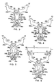
- Fig. 3 shows the trigger member 34 moved downwardly slightly from its cartridge holding position of Fig. 1.
- the movement of the drive pin in the main cam slots 44a and 44b has caused the first lever 24a to be rotated slightly clockwise from its Fig. 1 position and the lever 24b to be rotated slightly counterclockwise from its Fig. 1 position.
- the abutment pins 52a and 52b have not yet contacted the cocking springs 50a and 50b.
- Fig. 4 shows the trigger member 34 positioned somewhat downwardly from its Fig. 3 position.
- the first lever 24a has been rotated slightly more clockwise from its Fig. 3 position
- the lever 24b has been rotated slightly more counterclockwise from its Fig. 3 position
- the abutment pins 52a and 52b have contacted the cocking springs 50a and 50b to deflect them slightly from their unstressed positions shown by the broken lines at 50a and 50b.
- the trigger member 34 is shown to be moved downwardly from its Fig. 4 position to its cartridge release/capture position with the drive pin 46 having reached the vicinity of the cocking notches 48a and 48b.
- the abutment pins 52a and 52b have still further deflected the cocking springs 50a and 50b to exert relatively strong biasing forces on the arms 26a and 26b tending to rotate the arm 24a clockwise and the arm 24b counterclockwise.
- Fig. 6 shows the trigger member 34 in the same cartridge release/capture position as Fig. 5 but with the arms 26a and 26b being shown to have been moved by the forces applied on them by the cocking springs 50a and 50b, to bring the cocking notches 48a and 48b onto the drive pin 46.
Landscapes
- Life Sciences & Earth Sciences (AREA)
- Forests & Forestry (AREA)
- Engineering & Computer Science (AREA)
- Mechanical Engineering (AREA)
- Packaging Of Annular Or Rod-Shaped Articles, Wearing Apparel, Cassettes, Or The Like (AREA)
- Measurement Of The Respiration, Hearing Ability, Form, And Blood Characteristics Of Living Organisms (AREA)
Applications Claiming Priority (2)
| Application Number | Priority Date | Filing Date | Title |
|---|---|---|---|
| US32676601P | 2001-10-02 | 2001-10-02 | |
| US326766P | 2001-10-02 |
Publications (1)
| Publication Number | Publication Date |
|---|---|
| EP1300220A1 true EP1300220A1 (fr) | 2003-04-09 |
Family
ID=23273618
Family Applications (1)
| Application Number | Title | Priority Date | Filing Date |
|---|---|---|---|
| EP02021341A Withdrawn EP1300220A1 (fr) | 2001-10-02 | 2002-09-23 | Mécanisme pour retenir, libérer et recevoir une cartouche de lames remplaçable pour un rasoir |
Country Status (4)
| Country | Link |
|---|---|
| US (1) | US20030061718A1 (fr) |
| EP (1) | EP1300220A1 (fr) |
| JP (1) | JP2003117269A (fr) |
| CA (1) | CA2405337A1 (fr) |
Cited By (1)
| Publication number | Priority date | Publication date | Assignee | Title |
|---|---|---|---|---|
| CN111043114A (zh) * | 2019-10-22 | 2020-04-21 | 合肥兰舟智能科技有限公司 | 一种卡紧机构 |
Families Citing this family (19)
| Publication number | Priority date | Publication date | Assignee | Title |
|---|---|---|---|---|
| EP1308250A1 (fr) * | 2001-11-01 | 2003-05-07 | Warner-Lambert Company | Ensemble rasoir à cartouche remplaçable |
| AU2003212586A1 (en) * | 2002-05-16 | 2003-12-02 | Warner-Lambert Company Llc | Razor cartridge mounting structure |
| WO2004073939A1 (fr) * | 2003-02-19 | 2004-09-02 | Eveready Battery Company, Inc. | Cartouche de rasoir a lames multiples |
| WO2006081838A1 (fr) * | 2005-02-03 | 2006-08-10 | Bic-Violex Sa | Manche de rasoir presentant un profil arque |
| CA2596784A1 (fr) * | 2005-02-03 | 2006-08-10 | Bic-Violex Sa | Manche de rasoir comportant une zone appui-doigt sur coussin d'air |
| CA2596795A1 (fr) * | 2005-02-03 | 2006-08-10 | Bic-Violex Sa | Manche de rasoir comportant des zones de prehension ergonomiques |
| BRPI0519867B1 (pt) * | 2005-02-03 | 2019-03-19 | Bic-Violex Sa | Cabo de aparelho para barbear |
| CN100546778C (zh) * | 2005-02-03 | 2009-10-07 | 比克-维奥利克斯公司 | 具有会合的侧表面的剃刀手柄 |
| BRPI0519883A2 (pt) * | 2005-02-03 | 2009-09-15 | Bic Violex Sa | cabo de aparelho para barbear |
| KR100903191B1 (ko) * | 2007-05-31 | 2009-06-17 | 주식회사 도루코 | 면도기 |
| JP5052473B2 (ja) * | 2008-09-30 | 2012-10-17 | ノーレッジ・アンド・マーチャンダイジング・インコーポレーテッド・リミテッド | かみそり |
| US20100313426A1 (en) * | 2009-06-12 | 2010-12-16 | Terence Gordon Royle | Safety razor with pivot and rotation |
| US8474144B2 (en) * | 2009-08-12 | 2013-07-02 | The Gillette Company | Safety razor with rotational movement and locking button |
| EP3227065B1 (fr) * | 2014-12-05 | 2020-02-19 | BIC-Violex S.A. | Manche de rasoir avec un verrou et un mécanisme de libération pour un enclenchement et un désenclenchement avec une cartouche de rasoir |
| CN104739277B (zh) * | 2015-03-16 | 2017-06-13 | 浙江诺维雅工贸有限公司 | 一种可拆卸手柄 |
| KR102615110B1 (ko) * | 2016-04-05 | 2023-12-18 | 빅 비올렉스 싱글 멤버 에스.아. | 카트리지를 결속 및 결속 해제하기 위한 잠금 및 해제 메커니즘을 갖는 면도기 손잡이 |
| US10639808B2 (en) * | 2016-09-19 | 2020-05-05 | Xiangrong Ren | Elastic fastener for razor |
| US9993931B1 (en) | 2016-11-23 | 2018-06-12 | Personal Care Marketing And Research, Inc. | Razor docking and pivot |
| EP3978211A1 (fr) | 2020-10-01 | 2022-04-06 | Koninklijke Philips N.V. | Ensemble de montage et appareil de coupe de cheveux |
Citations (3)
| Publication number | Priority date | Publication date | Assignee | Title |
|---|---|---|---|---|
| US4083104A (en) * | 1975-05-12 | 1978-04-11 | The Gillette Company | Razor handle |
| EP0271185A2 (fr) * | 1986-12-08 | 1988-06-15 | Warner-Lambert Company | Rasoir mécanique à tête pivotante avec moyens de blocage de la tête |
| US5016352A (en) * | 1990-03-22 | 1991-05-21 | The Gillette Company | Single button razor |
Family Cites Families (8)
| Publication number | Priority date | Publication date | Assignee | Title |
|---|---|---|---|---|
| US4266340A (en) * | 1979-06-11 | 1981-05-12 | Warner-Lambert Company | Razor handle for mounting pivotable razor blade cartridges |
| AU638974B2 (en) * | 1989-06-05 | 1993-07-15 | Warner-Lambert Company | Razor mechanism |
| US5044077A (en) * | 1990-04-10 | 1991-09-03 | Warner-Lambert Company | Razor mechanism |
| US5157834A (en) * | 1990-04-10 | 1992-10-27 | Warner-Lambert Company | Razor mechanism with slidable cartridge support |
| GB9208098D0 (en) * | 1992-04-13 | 1992-05-27 | Gillette Co | Razor with movable cartridge |
| US5347717A (en) * | 1993-11-05 | 1994-09-20 | Ts Ai Tse Jen | Chuck assembly for a disposable razor |
| EP1308250A1 (fr) * | 2001-11-01 | 2003-05-07 | Warner-Lambert Company | Ensemble rasoir à cartouche remplaçable |
| JP3833171B2 (ja) * | 2001-12-21 | 2006-10-11 | ファイザー・プロダクツ・インク | 剃刀装置 |
-
2002
- 2002-09-23 EP EP02021341A patent/EP1300220A1/fr not_active Withdrawn
- 2002-09-26 CA CA002405337A patent/CA2405337A1/fr not_active Abandoned
- 2002-10-01 US US10/263,062 patent/US20030061718A1/en not_active Abandoned
- 2002-10-02 JP JP2002289674A patent/JP2003117269A/ja active Pending
Patent Citations (3)
| Publication number | Priority date | Publication date | Assignee | Title |
|---|---|---|---|---|
| US4083104A (en) * | 1975-05-12 | 1978-04-11 | The Gillette Company | Razor handle |
| EP0271185A2 (fr) * | 1986-12-08 | 1988-06-15 | Warner-Lambert Company | Rasoir mécanique à tête pivotante avec moyens de blocage de la tête |
| US5016352A (en) * | 1990-03-22 | 1991-05-21 | The Gillette Company | Single button razor |
Cited By (1)
| Publication number | Priority date | Publication date | Assignee | Title |
|---|---|---|---|---|
| CN111043114A (zh) * | 2019-10-22 | 2020-04-21 | 合肥兰舟智能科技有限公司 | 一种卡紧机构 |
Also Published As
| Publication number | Publication date |
|---|---|
| CA2405337A1 (fr) | 2003-04-02 |
| US20030061718A1 (en) | 2003-04-03 |
| JP2003117269A (ja) | 2003-04-22 |
Similar Documents
| Publication | Publication Date | Title |
|---|---|---|
| EP1300220A1 (fr) | Mécanisme pour retenir, libérer et recevoir une cartouche de lames remplaçable pour un rasoir | |
| US20040181953A1 (en) | Shaving implement | |
| US6560881B2 (en) | Shaving razor with pivoting blade carrier and replaceable blade cartridge therefor | |
| KR900002293B1 (ko) | 회동식 카트리지면도기의 핸들 | |
| US6929253B2 (en) | Quick action bar clamp with improved stiffness and release button | |
| US4514904A (en) | Razor handle | |
| JPH08500514A (ja) | 摺動可能なカートリッジ支持体を有するカミソリのハンドル | |
| WO2002000401A1 (fr) | Rasoir de surete | |
| CZ298839B6 (cs) | Výmenná hlavice holicího strojku a holicí strojeks touto hlavicí | |
| US4708502A (en) | Mounting mechanism for a print head | |
| AU734191B2 (en) | Impact/no-impact punchdown tool for use with cut/no-cut or wire insertion blade assembly | |
| JPS6013711B2 (ja) | 安全かみそりのカ−トリッジ替刃ホルダ− | |
| CN109571556B (zh) | 毛发切削设备 | |
| GB2362849A (en) | Unitary spring clip for retaining a razor cartridge on a handle | |
| US20020189112A1 (en) | Cartridge loading system for a razor assembly | |
| EP0271511B1 (fr) | Outil a main a cliquet a course multiple | |
| US7040208B2 (en) | Cutter cassette and cutting device | |
| US20120042522A1 (en) | Utility Knife | |
| EP0536652B1 (fr) | Outil de sertissage avec matrice tournante | |
| US4324496A (en) | Type disc printer | |
| CN112824066A (zh) | 刀具 | |
| JP4789143B2 (ja) | 散水ノズル | |
| US2226964A (en) | Blade retaining safety razor | |
| US5192260A (en) | Apparatus for transfer of a machine part | |
| EP0707526B1 (fr) | Tete de rasoir |
Legal Events
| Date | Code | Title | Description |
|---|---|---|---|
| PUAI | Public reference made under article 153(3) epc to a published international application that has entered the european phase |
Free format text: ORIGINAL CODE: 0009012 |
|
| AK | Designated contracting states |
Kind code of ref document: A1 Designated state(s): AT BE BG CH CY CZ DE DK EE ES FI FR GB GR IE IT LI LU MC NL PT SE SK TR Designated state(s): AT BE BG CH CY CZ DE DK EE ES FI FR GB GR IE IT LI LU MC NL PT SE SK TR |
|
| AX | Request for extension of the european patent |
Extension state: AL LT LV MK RO SI |
|
| STAA | Information on the status of an ep patent application or granted ep patent |
Free format text: STATUS: THE APPLICATION HAS BEEN WITHDRAWN |
|
| 18W | Application withdrawn |
Effective date: 20030919 |