EP1300237A2 - Verfahren und Vorrichtung zum Falten von plattenförmigen Elementen, insbesondere Kartonagen - Google Patents
Verfahren und Vorrichtung zum Falten von plattenförmigen Elementen, insbesondere Kartonagen Download PDFInfo
- Publication number
- EP1300237A2 EP1300237A2 EP02005381A EP02005381A EP1300237A2 EP 1300237 A2 EP1300237 A2 EP 1300237A2 EP 02005381 A EP02005381 A EP 02005381A EP 02005381 A EP02005381 A EP 02005381A EP 1300237 A2 EP1300237 A2 EP 1300237A2
- Authority
- EP
- European Patent Office
- Prior art keywords
- folding
- plate
- section
- shaped elements
- shaped element
- Prior art date
- Legal status (The legal status is an assumption and is not a legal conclusion. Google has not performed a legal analysis and makes no representation as to the accuracy of the status listed.)
- Granted
Links
Images

Classifications
-
- B—PERFORMING OPERATIONS; TRANSPORTING
- B65—CONVEYING; PACKING; STORING; HANDLING THIN OR FILAMENTARY MATERIAL
- B65B—MACHINES, APPARATUS OR DEVICES FOR, OR METHODS OF, PACKAGING ARTICLES OR MATERIALS; UNPACKING
- B65B5/00—Packaging individual articles in containers or receptacles, e.g. bags, sacks, boxes, cartons, cans, jars
- B65B5/02—Machines characterised by incorporation of means for making the containers or receptacles
- B65B5/024—Machines characterised by incorporation of means for making the containers or receptacles for making containers from preformed blanks
- B65B5/028—Machines characterised by incorporation of means for making the containers or receptacles for making containers from preformed blanks for making containers from two or more blanks
-
- B—PERFORMING OPERATIONS; TRANSPORTING
- B31—MAKING ARTICLES OF PAPER, CARDBOARD OR MATERIAL WORKED IN A MANNER ANALOGOUS TO PAPER; WORKING PAPER, CARDBOARD OR MATERIAL WORKED IN A MANNER ANALOGOUS TO PAPER
- B31B—MAKING CONTAINERS OF PAPER, CARDBOARD OR MATERIAL WORKED IN A MANNER ANALOGOUS TO PAPER
- B31B50/00—Making rigid or semi-rigid containers, e.g. boxes or cartons
- B31B50/26—Folding sheets, blanks or webs
- B31B50/36—Folding sheets, blanks or webs by continuously feeding the sheets, blanks or webs to stationary members, e.g. plates, ploughs or cores
-
- B—PERFORMING OPERATIONS; TRANSPORTING
- B31—MAKING ARTICLES OF PAPER, CARDBOARD OR MATERIAL WORKED IN A MANNER ANALOGOUS TO PAPER; WORKING PAPER, CARDBOARD OR MATERIAL WORKED IN A MANNER ANALOGOUS TO PAPER
- B31B—MAKING CONTAINERS OF PAPER, CARDBOARD OR MATERIAL WORKED IN A MANNER ANALOGOUS TO PAPER
- B31B50/00—Making rigid or semi-rigid containers, e.g. boxes or cartons
- B31B50/26—Folding sheets, blanks or webs
Definitions
- the present invention relates to a method for folding of plate-shaped elements, especially cardboard.
- the present invention further relates to a Device for folding plate-shaped elements for Execution of the procedure.
- Plate-shaped elements such as cardboard boxes
- folding of the cardboard boxes is usually necessary in order to enclose the object to be packed with the cardboard box.
- Methods for folding cardboard boxes and corresponding devices are known in the prior art, in which adjacent cardboard sections are folded along a folding edge, fixed or movable counterpressure elements being present along the folding edge and at least one cardboard section being bent around the axis of the folding edge.
- These known methods and devices for folding cardboard boxes initially have the disadvantage that the counterpressure elements lie inside the folded element after the folding process and have to be removed from there.
- the element to be folded and / or the counter-pressure elements must be moved and controlled in such a way that they abut against one another during the folding, which results in an increased complexity of the method and the device for folding. Particularly when there are a large number of consecutive folding processes, these are often carried out in continuous operation, ie the objects to be folded are passed through a folding device one after the other during the folding process.
- the arrangement of counterpressure elements is particularly disadvantageous in continuous operation, since the above-mentioned disadvantages of the prior art are amplified and the smooth passage of the elements to be folded is hindered by the counterpressure elements.
- the present invention is based on the technical problem of providing a method for folding plate-shaped elements, in particular cardboard boxes, which eliminates the disadvantages of the prior art, in particular in continuous operation, and is simple to carry out.
- a device for folding plate-shaped elements, in particular cardboard boxes is to be provided, which advantageously embodies the method.
- the present invention is based on the idea that the force component for the turning process on the not folding section of the plate-shaped element separate, complex counter pressure elements, but through the Vertical component of the contact force between the second Pressure device and plate-shaped element balanced becomes.
- the second printing device on the plate-shaped element can in the present invention to those in the prior art Technology required counter pressure elements along the Folding edge can be dispensed with.
- the folded edge of the plate-shaped elements is as Easier to fold, preferably as a cross-sectional taper and / or perforation. In this way the Predefined position of the folded edge and the position for folding required force is significantly reduced.
- the second printing device In order to control the folding process and the To reduce the design effort of the folding device takes the second printing device according to a development of the Invention during folding a stationary position, at which the second section of the plate-shaped elements is guided along. This is done with this training Do not fold the plate-shaped element by one Movement of the second printing device, but by the Movement of the plate-shaped element. Particularly advantageous is this procedure in the continuous process, because then the Continuous movement of the plate-shaped element through the Folding device at the same time as the folding process is being used.
- Printing device at least one role in folding the second section of the plate-shaped element rests.
- This arrangement is particularly advantageous if at the second printing device several in the direction of flow one behind the other rolls on the second Section of the plate-shaped element bear to a or more than one set of roles.
- the roles or roller sets guide the plate-shaped element in the Pass through the folder and are simultaneously arranged such that the second section of the plate-shaped element by the rollers or roller sets is folded.
- the alignment of the rollers or roller sets with respect to the plate-shaped element crucial.
- the axes run the rollers when folded substantially parallel to that on the Roll adjacent second section of the plate-shaped Element.
- the axes of the rollers point no right angle with respect to the fold edge, i.e. H. the Rollers are inclined in relation to the direction of flow.
- the invention Due to the inclination of the rollers, they don't run only along the second section of the plate-shaped Elements, but there is a frictional force between the Rolls and the second section, the invention a generates second force component, which in the plane of second section runs and in the direction of the folded edge acts. In this way, the first section of the plate-shaped element to the first printing device pressed.
- the amount of friction between the rollers and the second section of the plate-shaped elements can according to a development of the invention not only on the Arrangement of roles, but also on the interpretation of the Treads controlled with a certain coefficient of friction become.
- high friction coefficients of the tread which may be made of rubber, for example, to sufficient pressing of the plate-shaped element to ensure the first printing device.
- the geometry of the plate-shaped element or the desired folding angle to be able to adapt are the rolls around the folded edge pivotable and / or about an axis perpendicular to the second Section rotatable. This increases flexibility the folding device reached.
- the first printing device also has at least one Has role that when folding on the first section is applied.
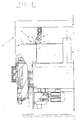
- the plate-shaped element 1 and 2 is a folding device according to the invention 10 schematically for folding a plate-shaped element 1 shown.
- the plate-shaped element 1 can for example, a cardboard box.
- the plate-shaped Element 1 has a first section 3, a second Section 4 and a folded edge 2, which is between the first Section 3 and the second section 4 of the plate-shaped Element 1 lies.
- the folded edge 2 has one Cross-sectional taper to the position of the folded edge 2 to predefine and fold the plate-shaped element 1 along the folded edge 2 to facilitate.
- the folding device 10 has a first one in FIG Printing device 5, which on the first section 3 of the plate-shaped element 1 abuts, and a second Printing device 6, which on the second section 4 of the plate-shaped element 1 abuts.
- the first and second Printing device 5, 6 are common on one Holding device 8 attached during folding a assumes a stationary position.
- Both printing devices have rollers 5 ', 6', with their treads 9 on the first and second section 3, 4 of the plate-shaped Element 1 apply.
- the running surfaces 9 of the rollers have a high coefficient of friction, for example, from Rubber.
- the rollers 6 'of the second printing device 6 are around Folding edge 2 pivotable and about an axis perpendicular to second section 4 rotatable.
- the folding device 10 is over the holding device 8 on a continuous system 9 for Transport and control of the plate-shaped element 1 attached during the folding process.
- a continuous system 9 for Transport and control of the plate-shaped element 1 attached during the folding process.
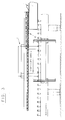
- a plurality of folding devices 10 in Direction of flow arranged one behind the other.
- the Axes of the rollers 6 'of the various folding devices 10 different pivoting angles around the folded edge 2 as well different angles of inclination with respect to the folded edge 2 on.
- the Continuous system 9 in FIG. 2 shows a lateral conveyor belt 11 on which on the plate-shaped element 1 on the second section 4 lies opposite side. Also it is possible that the continuous system 9 including the Folding device 10 and the plate-shaped element 1 symmetrical to the axis A-A shown in FIG. 2 are built up. In this way, two second sections 4 of the plate-shaped element 1 folded at the same time are no longer required during a conveyor belt 11 is.
- the plate-shaped element 1 is so in the Continuous system 9 inserted that the first and second Printing device 5, 6 on the first and second respectively Section of the plate-shaped element 1 of the Fold device 10 arranged to rest.
- the Continuous system 9 transports the plate-shaped element 1 in Throughput direction.
- the first and second slide Section 3, 4 along the in the direction of flow first and second arranged in series Printing devices 5, 6 of the folding devices 10.
- a second printing device 6 bends the second Section 4 of the plate-shaped element 1 around the folded edge 2 around.
- the rollers 6 have a frictional force between the second Printing device 6 and the second section 4, the one second force component in the plane of the second section 4 generated in the direction of the folded edge 2 and the first section 3 of the plate-shaped element 1 thereby to the first Presses pressure device 5.
- the second section 4 is folded by a certain angle, the height of which depends on the pivoting and tilting angle of the rollers 6 ′ of the respective second printing device 6. In this way, the plate-shaped element 1 is folded in a continuous process by a plurality of folding devices 10 arranged one behind the other until the desired folding angle is reached.
Landscapes
- Engineering & Computer Science (AREA)
- Mechanical Engineering (AREA)
- Folding Of Thin Sheet-Like Materials, Special Discharging Devices, And Others (AREA)
- Shaping Of Tube Ends By Bending Or Straightening (AREA)
- Making Paper Articles (AREA)
- Machines For Manufacturing Corrugated Board In Mechanical Paper-Making Processes (AREA)
- Diaphragms For Electromechanical Transducers (AREA)
Abstract
Description
Im Stand der Technik sind Verfahren zum Falten von Kartonagen sowie entsprechende Vorrichtungen bekannt, bei denen benachbarte Kartonabschnitte entlang einer Faltkante gefaltet werden, wobei entlang der Faltkante feste oder bewegliche Gegendruckelemente anliegen und zumindest ein Kartonabschnitt um die Achse der Faltkante herum gebogen wird.
Diese bekannten Verfahren und Vorrichtungen zum Falten von Kartonagen besitzen zunächst den Nachteil, dass die Gegendruckelemente nach dem Faltvorgang im Inneren des gefalteten Elementes liegen und von dort entfernt werden müssen. Darüber hinaus müssen das zu faltende Element und/oder die Gegendruckelemente derart verfahren und gesteuert werden, dass sie während des Faltens aneinander anliegen, was eine erhöhte Komplexität des Verfahrens und der Vorrichtung zum Falten mit sich bringt.
Insbesondere bei einer hohen Anzahl an nacheinanderfolgenden Faltvorgängen werden diese häufig im Durchlaufbetrieb durchgeführt, d. h. die zu faltenden Gegenstände werden während des Faltvorganges nacheinander durch eine Faltvorrichtung geführt.
Allerdings ist im Durchlaufbetrieb die Anordnung von Gegendruckelementen besonders nachteilig, da die oben genannten Nachteile des Standes der Technik verstärkt werden und der reibungslose Durchlauf der zu faltenden Elemente durch die Gegendruckelemente behindert wird.
Zusätzlich soll eine Vorrichtung zum Falten plattenförmiger Elemente, insbesondere von Kartonagen, bereitgestellt werden, die das Verfahren vorteilhaft ausgestaltet.
Auf diese Weise sind keine besonderen Vorrichtungen, wie beispielsweise formschlüssige Kontaktelemente zwischen dem zweiten Abschnitt des plattenförmigen Elementes und der zweiten Druckvorrichtung erforderlich. Allerdings kann es auch sinnvoll sein, dass das plattenförmige Element während des Faltens durch die erste und/oder zweite Druckvorrichtung gehalten ist, beispielsweise durch Kraft- oder Formschluss.
- Fig. 1a
- eine schematische Ansicht einer erfindungsgemäßen Faltvorrichtung mit einem plattenförmigen Element vor Beginn des Faltvorganges;
- Fig. 1b
- eine schematische Ansicht einer erfindungsgemäßen Faltvorrichtung mit einem plattenförmigen Element während des Faltvorganges;
- Fig. 1c
- eine schematische Ansicht einer erfindungsgemäßen Faltvorrichtung mit einem plattenförmigen Element nach Abschluss des Faltvorganges;
- Fig. 2
- eine schematische Ansicht einer erfindungsgemäßen Faltvorrichtung als Teil einer Durchlaufanlage zur Beförderung und Steuerung des plattenförmigen Elementes während des Faltvorganges;
- Fig. 3
- eine schematische Seitenansicht einer erfindungsgemäßen Faltvorrichtung als Teil einer Durchlaufanlage zur Beförderung und Steuerung des plattenförmigen Elementes während des Faltvorganges.
Auf diese Weise wird das plattenförmige Element 1 im Durchlaufverfahren durch mehrere hintereinander angeordnete Faltvorrichtungen 10 gefaltet, bis der gewünschte Faltwinkel erreicht ist.
Claims (14)
- Verfahren zum Falten von plattenförmigen Elementen (1) entlang einer Faltkante (2), die zwischen einem ersten Abschnitt (3) und einem zweiten Abschnitt (4) des plattenförmigen Elementes (1) liegt,
mittels einer ersten Druckvorrichtung (5) und einer zweiten Druckvorrichtung (6), die während des Faltvorganges an dem plattenförmigen Element (1) auf unterschiedlichen Seiten (3, 4) der Faltkante (2) anliegen,
bei dem die zweite Druckvorrichtung (6) den zweiten Abschnitt (4) des plattenförmigen Elementes (1) durch eine erste Kraftkomponente, die senkrecht zur Ebene des zweiten Abschnitts (4) steht, um die Faltkante (2) herum abbiegt,
und dabei eine zweite Kraftkomponente erzeugt, die in der Ebene des zweiten Abschnitts (4) verläuft sowie in Richtung der Faltkante (2) wirkt, und den ersten Abschnitt (3) des plattenförmigen Elementes (1) an die erste Druckvorrichtung (5) anpresst. - Verfahren zum Falten von plattenförmigen Elementen (1) nach Anspruch 1, dadurch gekennzeichnet, dass die Faltkante (2) des plattenförmigen Elementes (1) als Falterleichterung, insbesondere in Form einer Querschnittsverjüngung und/oder Perforation, erzeugt wird.
- Verfahren zum Falten von plattenförmigen Elementen (1) nach Anspruch 1 oder 2, dadurch gekennzeichnet, dass das Falten der plattenförmigen Elemente (1) im Durchlaufverfahren erfolgt.
- Verfahren zum Falten von plattenförmigen Elementen (1) nach einem der Ansprüche 1 bis 3, dadurch gekennzeichnet, dass die zweite Druckvorrichtung (6) während des Faltens der plattenförmigen Elemente (1) eine stationäre Position einnimmt, an welcher der zweite Abschnitt (4) entlanggeführt wird.
- Vorrichtung (10) zum Falten von plattenförmigen Elementen (1) entlang einer Faltkante (2), die zwischen einem ersten Abschnitt (3) und einem zweiten Abschnitt (4) des plattenförmigen Elementes (1) liegt,
wobei die Vorrichtung (10) eine erste Druckvorrichtung (5) und eine zweite Druckvorrichtung (6) aufweist, die während des Faltvorganges an dem plattenförmigen Element (1) auf unterschiedlichen Seiten (3, 4) der Faltkante (2) anliegen,
dadurch gekennzeichnet, dass
die zweite Druckvorrichtung (6) derart ausgebildet ist, dass die Kontaktkraft zwischen der zweiten Druckvorrichtung (6) und dem zweiten Abschnitt (4) des plattenförmigen Elementes (1) eine erste Kraftkomponente aufweist, die senkrecht zur Ebene des zweiten Abschnitts (4) steht,
und eine zweite Kraftkomponente aufweist, die in der Ebene des zweiten Abschnitts (4) verläuft sowie in Richtung der Faltkante (2) wirkt. - Vorrichtung (10) zum Falten von plattenförmigen Elementen (1) nach Anspruch 5, dadurch gekennzeichnet, dass die Faltkante (2) des plattenförmigen Elementes (1) als Falterleichterung, insbesondere als Querschnittsverjüngung und/oder Perforation, ausgebildet ist.
- Vorrichtung (10) zum Falten von plattenförmigen Elementen (1) nach Anspruch 5 oder 6, dadurch gekennzeichnet, dass die zweite Kraftkomponente, die in der Ebene des zweiten Abschnitts (4) verläuft sowie in Richtung der Faltkante (2) wirkt, eine Reibungskraft zwischen der zweiten Druckvorrichtung (6) und dem zweiten Abschnitt (4) ist.
- Vorrichtung (10) zum Falten von plattenförmigen Elementen (1) nach einem der Ansprüche 5 bis 7, dadurch gekennzeichnet, dass die zweite Druckvorrichtung (6) während des Faltens der plattenförmigen Elemente (1) eine stationäre Position einnimmt, an welcher der zweite Abschnitt (4) entlanggeführt wird.
- Vorrichtung (10) zum Falten von plattenförmigen Elementen (1) im Durchlaufverfahren nach einem der Ansprüche 5 bis 8, dadurch gekennzeichnet, dass die zweite Druckvorrichtung (6) zumindest eine Rolle (6') aufweist, die beim Falten an dem zweiten Abschnitt (4) anliegt.
- Vorrichtung (10) zum Falten von plattenförmigen Elementen (1) im Durchlaufverfahren nach Anspruche 9, dadurch gekennzeichnet, dass die zweite Druckvorrichtung (6) einen Rollensatz mit in Durchlaufrichtung hintereinander angeordneten Rollen (6') aufweist, die beim Falten an dem zweiten Abschnitt (4) anliegen.
- Vorrichtung (10) zum Falten von plattenförmigen Elementen (1) im Durchlaufverfahren nach Anspruch 9 oder 10, dadurch gekennzeichnet, dass die Achsen der Rollen (6') beim Falten im wesentlichen parallel zum zweiten Abschnitt (4) verlaufen und gegenüber der Faltkante (2) keinen rechten Winkel einnehmen.
- Vorrichtung (10) zum Falten von plattenförmigen Elementen (1) im Durchlaufverfahren nach einem der Ansprüche 9 bis 11, dadurch gekennzeichnet, dass die Rollen (6') um die Faltkante (2) schwenkbar und/oder um eine Achse senkrecht zum zweiten Abschnitt (4) drehbar sind.
- Vorrichtung (10) zum Falten von plattenförmigen Elementen (1) im Durchlaufverfahren nach einem der Ansprüche 9 bis 12, dadurch gekennzeichnet, dass die Rollen (6') Laufflächen mit einem hohen Reibungsbeiwert aufweisen.
- Vorrichtung (10) zum Falten von plattenförmigen Elementen (1) im Durchlaufverfahren nach einem der Ansprüche 5 bis 13, dadurch gekennzeichnet, dass die erste Druckvorrichtung (5) zumindest eine Rolle (5') aufweist, die beim Falten an dem ersten Abschnitt (3) anliegt.
Applications Claiming Priority (2)
| Application Number | Priority Date | Filing Date | Title |
|---|---|---|---|
| DE10149053A DE10149053A1 (de) | 2001-10-05 | 2001-10-05 | Verfahren zum Falten von plattenförmigen Elementen, insbesondere Kartonagen und Vorrichtung hierzu |
| DE10149053 | 2001-10-05 |
Publications (3)
| Publication Number | Publication Date |
|---|---|
| EP1300237A2 true EP1300237A2 (de) | 2003-04-09 |
| EP1300237A3 EP1300237A3 (de) | 2005-08-24 |
| EP1300237B1 EP1300237B1 (de) | 2006-10-04 |
Family
ID=7701433
Family Applications (1)
| Application Number | Title | Priority Date | Filing Date |
|---|---|---|---|
| EP02005381A Expired - Lifetime EP1300237B1 (de) | 2001-10-05 | 2002-03-15 | Verfahren und Vorrichtung zum Falten von plattenförmigen Elementen, insbesondere Kartonagen |
Country Status (7)
| Country | Link |
|---|---|
| US (2) | US20030083182A1 (de) |
| EP (1) | EP1300237B1 (de) |
| AT (1) | ATE341443T1 (de) |
| CA (1) | CA2403936C (de) |
| DE (2) | DE10149053A1 (de) |
| DK (1) | DK1300237T3 (de) |
| ES (1) | ES2272589T3 (de) |
Cited By (2)
| Publication number | Priority date | Publication date | Assignee | Title |
|---|---|---|---|---|
| EP2145755A1 (de) * | 2008-07-18 | 2010-01-20 | Eberle (Société par Actions Simplifiée) | Verfahren zur Formung von Winkelprofilen und Vorrichtung zur Umsetzung dieses Verfahrens |
| EP4308463A4 (de) * | 2021-04-30 | 2025-04-02 | Packsize LLC | Systeme und verfahren zum falten und halten von schachtelklappen |
Families Citing this family (5)
| Publication number | Priority date | Publication date | Assignee | Title |
|---|---|---|---|---|
| DK1342665T3 (da) | 2002-03-08 | 2006-04-10 | Ligmatech Automationssysteme | Fremgangsmåde ved fremstilling af en emballageenhed og indretning til udövelse af fremgangsmåden |
| DE102004026690B3 (de) * | 2004-05-28 | 2005-12-01 | Sig Technology Ag | Vorrichtung zum kontinuierlichen Falten von Zuschnitten aus Karton/Kunststoff-Verbundmaterial |
| US7549955B2 (en) * | 2004-12-01 | 2009-06-23 | Pitney Bowes Inc. | Method and device for creasing paper |
| US9156573B2 (en) * | 2011-03-30 | 2015-10-13 | Alkar-Rapidpak, Inc. | Packaging apparatuses and methods |
| US12296461B2 (en) * | 2022-01-19 | 2025-05-13 | Ime Automation Llc | Box folding structure for SCARA robot |
Family Cites Families (18)
| Publication number | Priority date | Publication date | Assignee | Title |
|---|---|---|---|---|
| FR1568223A (de) * | 1968-03-19 | 1969-05-23 | ||
| US3716962A (en) * | 1970-12-18 | 1973-02-20 | American Can Co | Carton flap folding mechanism |
| US3977306A (en) * | 1975-05-15 | 1976-08-31 | Flynn Burner Corporation | Automatic carton sealing system |
| DE2540649C2 (de) * | 1975-09-12 | 1982-10-21 | Heinz-Hermann 4904 Enger Pott | Falteinrichtung für Faltschachtelzuschnitte |
| US4211356A (en) * | 1977-10-20 | 1980-07-08 | Trio Kabushiki Kaisha | Buffered package |
| US4160406A (en) * | 1978-06-21 | 1979-07-10 | International Paper Company | Method and apparatus for erecting a carton |
| IT1133253B (it) * | 1980-03-18 | 1986-07-09 | Bsp Packaging System | Apparecchiatura per la tramformazione di fustellati in corrispondenti contenitori di forma parallelepipeda |
| DE3708317A1 (de) * | 1986-03-13 | 1988-06-23 | Canon Kk | Bilderzeugungseinrichtung |
| US4875668A (en) * | 1988-04-28 | 1989-10-24 | Computer Output Processors And Engineering, Inc. | High speed sheet folder and presser for automated mailing systems |
| US5106359A (en) * | 1991-09-16 | 1992-04-21 | Lott Michael E | Carton formation system |
| US5393291A (en) * | 1993-07-08 | 1995-02-28 | Marq Packaging Systems, Inc. | Mini case erector |
| US5531852A (en) * | 1994-04-28 | 1996-07-02 | Graphic Packaging Corporation | Apparatus and method for end sealing a carton |
| DE4439198A1 (de) * | 1994-11-06 | 1996-05-09 | Klett Alfred | Vorrichtung zur Bearbeitung eines entlang eines Förderwegs mit vorgegebener Fördergeschwindigkeit geförderten Zuschnitts |
| US5853360A (en) * | 1995-06-16 | 1998-12-29 | J & L Development, Inc. | Method and apparatus for producing a gusseted container |
| US5716314A (en) * | 1995-12-06 | 1998-02-10 | Corrugated Gear & Services, Inc. | Optimal angle corrugated board folder |
| US6226965B1 (en) * | 1999-12-08 | 2001-05-08 | Belcor Industries Inc | Inline case sealing system |
| US6569073B1 (en) * | 2000-09-20 | 2003-05-27 | Dell Products, L.P. | Telescoping platform assembly for packaging systems |
| ITBO20010057A1 (it) * | 2001-02-05 | 2002-08-05 | Baumer Srl | Metodo e sistema per chiudere i lembi delle testate di un imballo a manicotto |
-
2001
- 2001-10-05 DE DE10149053A patent/DE10149053A1/de not_active Ceased
-
2002
- 2002-03-15 EP EP02005381A patent/EP1300237B1/de not_active Expired - Lifetime
- 2002-03-15 DE DE50208322T patent/DE50208322D1/de not_active Expired - Lifetime
- 2002-03-15 DK DK02005381T patent/DK1300237T3/da active
- 2002-03-15 ES ES02005381T patent/ES2272589T3/es not_active Expired - Lifetime
- 2002-03-15 AT AT02005381T patent/ATE341443T1/de not_active IP Right Cessation
- 2002-09-18 CA CA2403936A patent/CA2403936C/en not_active Expired - Fee Related
- 2002-10-04 US US10/263,562 patent/US20030083182A1/en not_active Abandoned
-
2004
- 2004-02-26 US US10/786,099 patent/US6916280B2/en not_active Expired - Fee Related
Cited By (3)
| Publication number | Priority date | Publication date | Assignee | Title |
|---|---|---|---|---|
| EP2145755A1 (de) * | 2008-07-18 | 2010-01-20 | Eberle (Société par Actions Simplifiée) | Verfahren zur Formung von Winkelprofilen und Vorrichtung zur Umsetzung dieses Verfahrens |
| FR2933898A1 (fr) * | 2008-07-18 | 2010-01-22 | Eberle | Procede de formage de profiles de section angulaire et dispositif pour la mise en oeuvre de ce procede |
| EP4308463A4 (de) * | 2021-04-30 | 2025-04-02 | Packsize LLC | Systeme und verfahren zum falten und halten von schachtelklappen |
Also Published As
| Publication number | Publication date |
|---|---|
| US20040180772A1 (en) | 2004-09-16 |
| US6916280B2 (en) | 2005-07-12 |
| EP1300237B1 (de) | 2006-10-04 |
| ATE341443T1 (de) | 2006-10-15 |
| ES2272589T3 (es) | 2007-05-01 |
| CA2403936C (en) | 2011-08-02 |
| DE10149053A1 (de) | 2003-04-24 |
| DE50208322D1 (de) | 2006-11-16 |
| DK1300237T3 (da) | 2007-01-29 |
| CA2403936A1 (en) | 2003-04-05 |
| US20030083182A1 (en) | 2003-05-01 |
| EP1300237A3 (de) | 2005-08-24 |
Similar Documents
| Publication | Publication Date | Title |
|---|---|---|
| DE69425006T2 (de) | Vorrichtung zum Fördern von Bogen mit Rollen | |
| WO2023134997A1 (de) | Gebindebildevorrichtung sowie verfahren zum wechsel von transportgruppen | |
| DE3124626A1 (de) | Transportvorrichtung fuer parallelepipede kartons | |
| EP1300237B1 (de) | Verfahren und Vorrichtung zum Falten von plattenförmigen Elementen, insbesondere Kartonagen | |
| EP2988926B1 (de) | Faltstation und faltschachtelklebemaschine | |
| DE4243222C2 (de) | Vorrichtung zum Transport und zur Verlangsamung von Falzprodukten | |
| EP3587283B1 (de) | Verpackungsmaschine zum verpacken mit dehnfolie und optimiertes verpackungsverfahren | |
| DE10043166C2 (de) | Vorrichtung zur Verbindung von Bandmaterial | |
| DE1536485B1 (de) | Vorrichtung zum Einbinden von Buchbloecken | |
| DE102013106268A1 (de) | Verfahren und Vorrichtung zur Herstellung rotationssymmetrischer Metallbauteile | |
| DE19857205B4 (de) | Verfahren zum Aufwickeln einer kontinuierlich zugeführten Materialbahn | |
| DE2365924C3 (de) | Schleifeinrichtung für Karden oder Krempel | |
| DE19649326A1 (de) | Vorrichtung zum Aufteilen eines Stromes von Signaturen | |
| EP0170961A1 (de) | Vorrichtung zum Längsfalzen übereinanderliegender Bahnen | |
| EP3969257A1 (de) | Rückschrumpf und kettenspanner einer folienreckanlage mit längsschrumpf | |
| EP1862567B1 (de) | Verfahren zur Abdichtung einer Vakuumkammer und Schleuseneinrichtung für eine Vakuumkammer | |
| EP3967485A2 (de) | Faltschachtelklebemaschine mit prägeeinrichtung | |
| DE2823047A1 (de) | Vorrichtung zum mehrfachen falten von waeschestuecken | |
| EP1342665B1 (de) | Verfahren und Vorrichtung zum Herstellung einer Verpackungseinheit | |
| DE2728336A1 (de) | Geraet zur erzeugung von falzlinien | |
| EP0096206A2 (de) | Stufenloses Getriebe | |
| EP1108672A2 (de) | Verfahren und Vorrichtung zum linearen Falzen | |
| EP2409922A1 (de) | Führungsvorrichtung einer Spreizeinheit und Verfahren zum Führen von wenigstens einem Materialbahnende in einer Verpackungsmaschine | |
| DE19535632A1 (de) | Verfahren und Vorrichtung zur Querkraftbeaufschlagung einer Bedruckstoffbahn | |
| DE10309020A1 (de) | Formschulter und Verfahren zu ihrer Herstellung |
Legal Events
| Date | Code | Title | Description |
|---|---|---|---|
| PUAI | Public reference made under article 153(3) epc to a published international application that has entered the european phase |
Free format text: ORIGINAL CODE: 0009012 |
|
| AK | Designated contracting states |
Kind code of ref document: A2 Designated state(s): AT BE CH CY DE DK ES FI FR GB GR IE IT LI LU MC NL PT SE TR Designated state(s): AT BE CH CY DE DK ES FI FR GB GR IE IT LI LU MC NL PT SE TR |
|
| AX | Request for extension of the european patent |
Extension state: AL LT LV MK RO SI |
|
| RIN1 | Information on inventor provided before grant (corrected) |
Inventor name: TOENNIGS, BODO Inventor name: UHLEMANN, LUTZ |
|
| PUAL | Search report despatched |
Free format text: ORIGINAL CODE: 0009013 |
|
| AK | Designated contracting states |
Kind code of ref document: A3 Designated state(s): AT BE CH CY DE DK ES FI FR GB GR IE IT LI LU MC NL PT SE TR |
|
| AX | Request for extension of the european patent |
Extension state: AL LT LV MK RO SI |
|
| 17P | Request for examination filed |
Effective date: 20051025 |
|
| AKX | Designation fees paid |
Designated state(s): AT BE CH CY DE DK ES FI FR GB GR IE IT LI LU MC NL PT SE TR |
|
| GRAP | Despatch of communication of intention to grant a patent |
Free format text: ORIGINAL CODE: EPIDOSNIGR1 |
|
| GRAS | Grant fee paid |
Free format text: ORIGINAL CODE: EPIDOSNIGR3 |
|
| GRAA | (expected) grant |
Free format text: ORIGINAL CODE: 0009210 |
|
| AK | Designated contracting states |
Kind code of ref document: B1 Designated state(s): AT BE CH CY DE DK ES FI FR GB GR IE IT LI LU MC NL PT SE TR |
|
| PG25 | Lapsed in a contracting state [announced via postgrant information from national office to epo] |
Ref country code: IT Free format text: LAPSE BECAUSE OF FAILURE TO SUBMIT A TRANSLATION OF THE DESCRIPTION OR TO PAY THE FEE WITHIN THE PRESCRIBED TIME-LIMIT;WARNING: LAPSES OF ITALIAN PATENTS WITH EFFECTIVE DATE BEFORE 2007 MAY HAVE OCCURRED AT ANY TIME BEFORE 2007. THE CORRECT EFFECTIVE DATE MAY BE DIFFERENT FROM THE ONE RECORDED. Effective date: 20061004 Ref country code: NL Free format text: LAPSE BECAUSE OF FAILURE TO SUBMIT A TRANSLATION OF THE DESCRIPTION OR TO PAY THE FEE WITHIN THE PRESCRIBED TIME-LIMIT Effective date: 20061004 Ref country code: IE Free format text: LAPSE BECAUSE OF FAILURE TO SUBMIT A TRANSLATION OF THE DESCRIPTION OR TO PAY THE FEE WITHIN THE PRESCRIBED TIME-LIMIT Effective date: 20061004 |
|
| REG | Reference to a national code |
Ref country code: GB Ref legal event code: FG4D Free format text: NOT ENGLISH |
|
| GBT | Gb: translation of ep patent filed (gb section 77(6)(a)/1977) |
Effective date: 20061004 |
|
| REG | Reference to a national code |
Ref country code: CH Ref legal event code: EP |
|
| REG | Reference to a national code |
Ref country code: IE Ref legal event code: FG4D Free format text: LANGUAGE OF EP DOCUMENT: GERMAN |
|
| REF | Corresponds to: |
Ref document number: 50208322 Country of ref document: DE Date of ref document: 20061116 Kind code of ref document: P |
|
| REG | Reference to a national code |
Ref country code: SE Ref legal event code: TRGR |
|
| REG | Reference to a national code |
Ref country code: DK Ref legal event code: T3 |
|
| PG25 | Lapsed in a contracting state [announced via postgrant information from national office to epo] |
Ref country code: PT Free format text: LAPSE BECAUSE OF FAILURE TO SUBMIT A TRANSLATION OF THE DESCRIPTION OR TO PAY THE FEE WITHIN THE PRESCRIBED TIME-LIMIT Effective date: 20070316 |
|
| ET | Fr: translation filed | ||
| NLV1 | Nl: lapsed or annulled due to failure to fulfill the requirements of art. 29p and 29m of the patents act | ||
| REG | Reference to a national code |
Ref country code: ES Ref legal event code: FG2A Ref document number: 2272589 Country of ref document: ES Kind code of ref document: T3 |
|
| REG | Reference to a national code |
Ref country code: IE Ref legal event code: FD4D |
|
| PLBE | No opposition filed within time limit |
Free format text: ORIGINAL CODE: 0009261 |
|
| STAA | Information on the status of an ep patent application or granted ep patent |
Free format text: STATUS: NO OPPOSITION FILED WITHIN TIME LIMIT |
|
| 26N | No opposition filed |
Effective date: 20070705 |
|
| REG | Reference to a national code |
Ref country code: CH Ref legal event code: PL |
|
| BERE | Be: lapsed |
Owner name: LIGMATECH AUTOMATIONSSYSTEME G.M.B.H. Effective date: 20070331 |
|
| PG25 | Lapsed in a contracting state [announced via postgrant information from national office to epo] |
Ref country code: BE Free format text: LAPSE BECAUSE OF NON-PAYMENT OF DUE FEES Effective date: 20070331 |
|
| PG25 | Lapsed in a contracting state [announced via postgrant information from national office to epo] |
Ref country code: MC Free format text: LAPSE BECAUSE OF NON-PAYMENT OF DUE FEES Effective date: 20070331 |
|
| PG25 | Lapsed in a contracting state [announced via postgrant information from national office to epo] |
Ref country code: LI Free format text: LAPSE BECAUSE OF NON-PAYMENT OF DUE FEES Effective date: 20070331 Ref country code: CH Free format text: LAPSE BECAUSE OF NON-PAYMENT OF DUE FEES Effective date: 20070331 |
|
| PG25 | Lapsed in a contracting state [announced via postgrant information from national office to epo] |
Ref country code: GR Free format text: LAPSE BECAUSE OF FAILURE TO SUBMIT A TRANSLATION OF THE DESCRIPTION OR TO PAY THE FEE WITHIN THE PRESCRIBED TIME-LIMIT Effective date: 20070105 |
|
| PG25 | Lapsed in a contracting state [announced via postgrant information from national office to epo] |
Ref country code: AT Free format text: LAPSE BECAUSE OF NON-PAYMENT OF DUE FEES Effective date: 20070315 |
|
| PG25 | Lapsed in a contracting state [announced via postgrant information from national office to epo] |
Ref country code: LU Free format text: LAPSE BECAUSE OF NON-PAYMENT OF DUE FEES Effective date: 20070315 Ref country code: CY Free format text: LAPSE BECAUSE OF FAILURE TO SUBMIT A TRANSLATION OF THE DESCRIPTION OR TO PAY THE FEE WITHIN THE PRESCRIBED TIME-LIMIT Effective date: 20061004 |
|
| PGRI | Patent reinstated in contracting state [announced from national office to epo] |
Ref country code: IT Effective date: 20110616 |
|
| PGFP | Annual fee paid to national office [announced via postgrant information from national office to epo] |
Ref country code: TR Payment date: 20120305 Year of fee payment: 11 |
|
| PGFP | Annual fee paid to national office [announced via postgrant information from national office to epo] |
Ref country code: FI Payment date: 20120319 Year of fee payment: 11 Ref country code: GB Payment date: 20120124 Year of fee payment: 11 |
|
| PGFP | Annual fee paid to national office [announced via postgrant information from national office to epo] |
Ref country code: DK Payment date: 20130304 Year of fee payment: 12 Ref country code: SE Payment date: 20130318 Year of fee payment: 12 Ref country code: ES Payment date: 20130305 Year of fee payment: 12 Ref country code: FR Payment date: 20130327 Year of fee payment: 12 |
|
| PG25 | Lapsed in a contracting state [announced via postgrant information from national office to epo] |
Ref country code: FI Free format text: LAPSE BECAUSE OF NON-PAYMENT OF DUE FEES Effective date: 20130315 |
|
| GBPC | Gb: european patent ceased through non-payment of renewal fee |
Effective date: 20130315 |
|
| PG25 | Lapsed in a contracting state [announced via postgrant information from national office to epo] |
Ref country code: GB Free format text: LAPSE BECAUSE OF NON-PAYMENT OF DUE FEES Effective date: 20130315 |
|
| PG25 | Lapsed in a contracting state [announced via postgrant information from national office to epo] |
Ref country code: TR Free format text: LAPSE BECAUSE OF NON-PAYMENT OF DUE FEES Effective date: 20130315 |
|
| PGFP | Annual fee paid to national office [announced via postgrant information from national office to epo] |
Ref country code: IT Payment date: 20140324 Year of fee payment: 13 |
|
| REG | Reference to a national code |
Ref country code: DK Ref legal event code: EBP Effective date: 20140331 |
|
| REG | Reference to a national code |
Ref country code: SE Ref legal event code: EUG |
|
| PG25 | Lapsed in a contracting state [announced via postgrant information from national office to epo] |
Ref country code: SE Free format text: LAPSE BECAUSE OF NON-PAYMENT OF DUE FEES Effective date: 20140316 |
|
| REG | Reference to a national code |
Ref country code: FR Ref legal event code: ST Effective date: 20141128 |
|
| PG25 | Lapsed in a contracting state [announced via postgrant information from national office to epo] |
Ref country code: FR Free format text: LAPSE BECAUSE OF NON-PAYMENT OF DUE FEES Effective date: 20140331 |
|
| REG | Reference to a national code |
Ref country code: ES Ref legal event code: FD2A Effective date: 20150428 |
|
| PG25 | Lapsed in a contracting state [announced via postgrant information from national office to epo] |
Ref country code: DK Free format text: LAPSE BECAUSE OF NON-PAYMENT OF DUE FEES Effective date: 20140331 |
|
| PG25 | Lapsed in a contracting state [announced via postgrant information from national office to epo] |
Ref country code: ES Free format text: LAPSE BECAUSE OF NON-PAYMENT OF DUE FEES Effective date: 20140316 |
|
| PG25 | Lapsed in a contracting state [announced via postgrant information from national office to epo] |
Ref country code: IT Free format text: LAPSE BECAUSE OF FAILURE TO SUBMIT A TRANSLATION OF THE DESCRIPTION OR TO PAY THE FEE WITHIN THE PRESCRIBED TIME-LIMIT Effective date: 20150315 |
|
| REG | Reference to a national code |
Ref country code: DE Ref legal event code: R079 Ref document number: 50208322 Country of ref document: DE Free format text: PREVIOUS MAIN CLASS: B31B0001260000 Ipc: B31B0050260000 |
|
| PGFP | Annual fee paid to national office [announced via postgrant information from national office to epo] |
Ref country code: DE Payment date: 20200309 Year of fee payment: 19 |
|
| REG | Reference to a national code |
Ref country code: DE Ref legal event code: R119 Ref document number: 50208322 Country of ref document: DE |
|
| PG25 | Lapsed in a contracting state [announced via postgrant information from national office to epo] |
Ref country code: DE Free format text: LAPSE BECAUSE OF NON-PAYMENT OF DUE FEES Effective date: 20211001 |