EP1300283A2 - Boucle de fixation pour le compartiment de chargement d'un véhicule - Google Patents
Boucle de fixation pour le compartiment de chargement d'un véhicule Download PDFInfo
- Publication number
- EP1300283A2 EP1300283A2 EP02021528A EP02021528A EP1300283A2 EP 1300283 A2 EP1300283 A2 EP 1300283A2 EP 02021528 A EP02021528 A EP 02021528A EP 02021528 A EP02021528 A EP 02021528A EP 1300283 A2 EP1300283 A2 EP 1300283A2
- Authority
- EP
- European Patent Office
- Prior art keywords
- rail
- load eye
- load
- base body
- eye according
- Prior art date
- Legal status (The legal status is an assumption and is not a legal conclusion. Google has not performed a legal analysis and makes no representation as to the accuracy of the status listed.)
- Withdrawn
Links
- 229910000831 Steel Inorganic materials 0.000 description 6
- 239000010959 steel Substances 0.000 description 6
- 230000000694 effects Effects 0.000 description 2
- 230000010354 integration Effects 0.000 description 2
- 230000003993 interaction Effects 0.000 description 2
- 208000027418 Wounds and injury Diseases 0.000 description 1
- 230000006978 adaptation Effects 0.000 description 1
- 230000006378 damage Effects 0.000 description 1
- 230000001419 dependent effect Effects 0.000 description 1
- 238000011161 development Methods 0.000 description 1
- 230000018109 developmental process Effects 0.000 description 1
- 238000005553 drilling Methods 0.000 description 1
- 238000010348 incorporation Methods 0.000 description 1
- 208000014674 injury Diseases 0.000 description 1
- 238000012986 modification Methods 0.000 description 1
- 230000004048 modification Effects 0.000 description 1
- 230000003287 optical effect Effects 0.000 description 1
- 230000003313 weakening effect Effects 0.000 description 1
Images


Classifications
-
- B—PERFORMING OPERATIONS; TRANSPORTING
- B60—VEHICLES IN GENERAL
- B60R—VEHICLES, VEHICLE FITTINGS, OR VEHICLE PARTS, NOT OTHERWISE PROVIDED FOR
- B60R5/00—Compartments within vehicle body primarily intended or sufficiently spacious for trunks, suit-cases, or the like
- B60R5/04—Compartments within vehicle body primarily intended or sufficiently spacious for trunks, suit-cases, or the like arranged at rear of vehicle
-
- B—PERFORMING OPERATIONS; TRANSPORTING
- B60—VEHICLES IN GENERAL
- B60P—VEHICLES ADAPTED FOR LOAD TRANSPORTATION OR TO TRANSPORT, TO CARRY, OR TO COMPRISE SPECIAL LOADS OR OBJECTS
- B60P7/00—Securing or covering of load on vehicles
- B60P7/06—Securing of load
- B60P7/08—Securing to the vehicle floor or sides
- B60P7/0807—Attachment points
- B60P7/0815—Attachment rails or trellis
Definitions
- the invention relates to a lifting eye for the hold of a motor vehicle.
- Such lifting eyes are generally known and are in the cargo or trunk of a car rigidly attached.
- the function of these load eyes which are also called lashing eyes and often the shape of a Have hook, consists in items to be packed in the trunk to lash firmly to the lifting eyes using straps to thereby to prevent the objects from slipping while driving. It has been shown in the past that heavy in the trunk objects if they slip while driving, lead to a different driving behavior of the car, which in particular in extreme situations such as fast cornering, at a risky moment can grow out. There is also the risk that strong Braking maneuvers the objects in the trunk such as "projectiles" fly towards the windscreen of the vehicle and in the Cars can injure people. All of this can be done with appropriate Lashing the items with straps on the lifting eyes be prevented.
- the lifting eye according to the invention has the features of claim 1 the advantage that the lifting eye depends on the shape of the object to be secured can be inserted in an appropriate position in a rail-shaped holder and / or displaceable therein, then after finding the ideal fixation point the rail-shaped bracket can be locked at this point is in that the lifting eye has a locking element which in corresponding Can snap holes in the rail-shaped bracket. Accordingly, can be the ideal mounting point for every object to be secured can be set for the lifting eye, which ensures a high level of security is achieved for the passengers in the motor vehicle.
- the lifting eye is essentially continuously shiftable and lockable in the rail-shaped holder, so that an even more optimal adjustment of the shackle to the objects to be secured is possible.
- the locking element is preferably designed as a locking pin.
- the bores are advantageously in the form of perforated strips in the Rail-shaped bracket can be inserted so that any adaptations can be made the respective requirements regarding the adjustability of the lifting eye can be achieved within the rail-shaped bracket. Should So a rough grid with regard to the holes in the rail-shaped Brackets are sufficient, perforated strips can be used whose holes are spaced apart from each other. If a more precise adjustment or adjustability of the lifting eye is required, paper tape with a larger number of holes must be used.
- the locking pin In order to lock the Locking pins in the holes of the paper tape inside the rail To achieve holder, the locking pin is biased into its locking position.
- the lifting eye Since the lifting eye is, of course, simple and easy on the one hand for cost reasons producible in a short time and on the other hand with a high The degree of reliability and resilience must be designed, the lifting eye has a base body and a bracket connected to it on, wherein the base body is guided in the rail-shaped holder. As a result, the lifting eye essentially consists of two components, which can be produced in a simple form. In addition, the use proven from brackets even with the known rigidly fixed lifting eyes. There is also the possibility of different bracket sizes and -thicknesses to combine with the basic body, depending on the application to be able to use the suitable lifting eye according to the invention.
- the Basic body a button, in particular a rocker button for actuation the locking pin.
- buttons are in a simple form in the base body to integrate and require a direct implementation of their activity in a movement of the locking pin either in the locking position or in the released position.
- Rocker buttons ensure that yours The respective position indicates whether the locking pin is in its locking position or detached position.
- the base body is preferably connected to the locking pin, so that when the lifting eye is removed from the rail-shaped holder only one component can be operated and handled.
- the load eye can also have the load eye with additional parts for motor vehicles, in particular Storage boxes and bike racks, can be connected or designed in one piece his.
- additional parts like storage boxes and bike racks, securely in the rail-shaped Mountable, slidable and then lockable are.
- the rail-shaped bracket made of an inner C-profile and an outer one Profile exist, which offers the possibility of drilling for the interaction with the locking element directly in the inner profile to be punched in so that the additional provision of a paper tape is not necessary.
- the outer profile has the advantageous effect that the Side panel is attachable by means of the outer profile and the Loading floor can be accommodated in it. Hence there is one Simplifying the attachment of the side panel in the cargo area of a Vehicle as well as a more handsome appearance.
- the rail-shaped bracket can be in the form of a or several rails in the hold and / or in the back of the
- Rear seats can be integrated. On the one hand, this requires a level Loading area, because in this case the rail-shaped bracket is not from the Base area of the cargo space protrudes, and on the other hand, the Optical impression of the cargo space through the integration of the rail-shaped Bracket not affected.
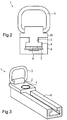
- Fig. 1 is a lifting eye 1 according to the invention in a perspective exploded view shown.
- the load eye 1 comprises a base body 2, on which a steel bracket 3 is attached.
- the steel bracket 3 reaches Purposes of lashing objects in the holds of motor vehicles about a strap or a rope.
- the steel bracket 3 is fixed to the Base body 2 connected.
- the steel bracket 3 can also be replaced can be combined with the base body 2.
- you can too the steel bracket has 3 different shapes, depending on the application.
- a button 4 is provided, which with a Underside of the base body 2 located locking pin 5 is connected. That is, when the button 4 is actuated, the locking pin 5 moves in FIG. 1 in the vertical direction either into its locked position in a bore 6 a perforated strip 7 inside the rail 8 or in a released position, in which the base body 2 is displaceable within the rail 8 is.
- the base body 2 in order to achieve this displaceability of the base body 2 in the rail 8, the base body 2, as shown in Fig. 1, has a double T-shape on, with the lower horizontal leg 9 inside the rail 8, as can be seen in particular from FIG. 2, and the upper horizontal leg 10 rests on the top of the rail 8.
- the locking pin 5 is also formed with a bearing pin 11, the adequate storage of the locking pin in a released position the bottom of the horizontal leg 9 conditional.
- the eyelet 1 according to the invention is in the inserted state in the rail 8 shown in front view. 2 is particular here It can be seen that the base body 2 and the locking pin 5 are above the hole strip is slidably guided and, although not shown, in the locked Position engages in a bore 6.
- the perforated strip 7 is in the rail 8 can be inserted and can therefore also be replaced in order Depending on requirements, perforated rails with more or fewer holes to use.
- FIGS. 3 and 4 show still further views of the invention Load eye 1.
- the rail 8 can either be in the hold of a car can be integrated or later in the cargo hold be attached.
- the rail 8 can also be connected to secure locking ensure these items in the hold.
- Rails 8 in the cargo hold is of course also possible Rail 8 on the rear of the backrest facing the cargo space to integrate in order to use eyelets according to the invention here too.
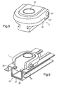
- FIG. 5 is a second embodiment of an inventive Last eye 1 'shown.
- this load eye 1 ' is a bracket 20 to one in Base body 21 mounted pin 22 pivotally mounted.
- the basic body 21 has a shape similar to that of the base body 3 of FIG first embodiment of the load eye 1, however, were over a rail 25 protruding edges rounded, in particular 5 and 6 can be seen.
- the invention Load eye 1 'in the pivoted-in state of the bracket 20 according to FIG. 5 23 button over the bracket 20 so that a slight actuation of the Button 23 is also possible in poor lighting conditions.
- Regarding the concrete geometric design of the lifting eye according to the invention 1 ' is explicitly referred to FIG. 5.
- the lifting eye 1 ' now shows a combination of the modified lifting eye 1 ' modified rail 25 shown in perspective view.
- the related on the rail 8 of the first embodiment of the invention Load eye 1 modified rail 25 of the second embodiment the lifting eye 1 'according to the invention consists of two profiles, namely an inner C-profile 26 and an outer profile 27.
- the first embodiment are those with a not shown Locking element interacting holes (not shown) introduced directly into the inner profile 26, whereas the first Embodiment, as described above, the holes 6 in one Paper tape 7 are incorporated, which in turn is inserted into the rail 8 becomes.
- This modified configuration of the rail 25 naturally enables also, the holes not only in the base of the inner rail 26, but also to incorporate into the side surfaces, depending on the application, at the same time, however, to achieve adequate functionality.
- the outer rail 27 is on its two outer sides formed with corresponding additional elements 28, 29, the on the one hand for receiving the loading floor and on the other hand for fastening serve the side paneling of the hold of a car.
- additional elements 28, 29 shown in FIG. 6, of course also depending on the use of the lifting eye 1 'according to the invention with modified Rail 25 differently designed additional elements on the outer rail 26 be provided.
- Last eyelet 1 Since the function of the load eye 1 'essentially that of Last eyelet 1 corresponds to the previous explanation in this regard referred in connection with the load eye 1. Of course there is also the possibility of the base body 2 with associated components in one Rail 25 and the base body 21 with associated components in one Insert rail 8.
- both the rail 8 and also the rail 25 can be provided with openings that one Use or removal of the lashing eyes 1, 1 'according to the invention enable.
- the rails 8, 25 have suitable weakenings of the profile cross section designed so that in the event of a rear-end crash can buckle the rails and not cause an injury to im Lead rear seated persons.
Landscapes
- Engineering & Computer Science (AREA)
- Mechanical Engineering (AREA)
- Transportation (AREA)
- Fittings On The Vehicle Exterior For Carrying Loads, And Devices For Holding Or Mounting Articles (AREA)
- Load-Engaging Elements For Cranes (AREA)
- Forklifts And Lifting Vehicles (AREA)
- Seats For Vehicles (AREA)
- Vehicle Step Arrangements And Article Storage (AREA)
Priority Applications (1)
| Application Number | Priority Date | Filing Date | Title |
|---|---|---|---|
| EP03028543A EP1398208B1 (fr) | 2001-10-05 | 2002-09-26 | Boucle de fixation pour le compartiment de chargement d'un véhicule |
Applications Claiming Priority (2)
| Application Number | Priority Date | Filing Date | Title |
|---|---|---|---|
| DE10149186 | 2001-10-05 | ||
| DE10149186A DE10149186B4 (de) | 2001-10-05 | 2001-10-05 | Lastöse mit einer schienenförmigen Halterung für den Laderaum eines Kraftfahrzeuges |
Related Child Applications (1)
| Application Number | Title | Priority Date | Filing Date |
|---|---|---|---|
| EP03028543A Division EP1398208B1 (fr) | 2001-10-05 | 2002-09-26 | Boucle de fixation pour le compartiment de chargement d'un véhicule |
Publications (2)
| Publication Number | Publication Date |
|---|---|
| EP1300283A2 true EP1300283A2 (fr) | 2003-04-09 |
| EP1300283A3 EP1300283A3 (fr) | 2003-05-14 |
Family
ID=7701524
Family Applications (2)
| Application Number | Title | Priority Date | Filing Date |
|---|---|---|---|
| EP02021528A Withdrawn EP1300283A3 (fr) | 2001-10-05 | 2002-09-26 | Boucle de fixation pour le compartiment de chargement d'un véhicule |
| EP03028543A Expired - Lifetime EP1398208B1 (fr) | 2001-10-05 | 2002-09-26 | Boucle de fixation pour le compartiment de chargement d'un véhicule |
Family Applications After (1)
| Application Number | Title | Priority Date | Filing Date |
|---|---|---|---|
| EP03028543A Expired - Lifetime EP1398208B1 (fr) | 2001-10-05 | 2002-09-26 | Boucle de fixation pour le compartiment de chargement d'un véhicule |
Country Status (2)
| Country | Link |
|---|---|
| EP (2) | EP1300283A3 (fr) |
| DE (2) | DE10149186B4 (fr) |
Cited By (6)
| Publication number | Priority date | Publication date | Assignee | Title |
|---|---|---|---|---|
| WO2004052681A1 (fr) * | 2002-12-11 | 2004-06-24 | Daimlerchrysler Ag | Espace de chargement d'automobile |
| WO2005065993A1 (fr) * | 2004-01-08 | 2005-07-21 | Bayerische Motoren Werke Aktiengesellschaft | Rail de charge |
| EP1816031A3 (fr) * | 2006-02-07 | 2008-04-02 | Manfred Berger | Système de fixation |
| CN103963975A (zh) * | 2013-01-29 | 2014-08-06 | 中国航空工业集团公司西安飞机设计研究所 | 一种可调间距式货盘限位装置 |
| FR3010023A1 (fr) * | 2013-08-30 | 2015-03-06 | Peugeot Citroen Automobiles Sa | Dispositif d'amarrage d'un organe d'accroche d'une sangle de filet de protection de vehicule automobile a la partie basse du chassis. |
| CN106956641A (zh) * | 2015-11-25 | 2017-07-18 | 福特全球技术公司 | 铰链式货物栓系夹 |
Families Citing this family (23)
| Publication number | Priority date | Publication date | Assignee | Title |
|---|---|---|---|---|
| DE10321890B4 (de) * | 2003-05-07 | 2005-10-27 | Bos Gmbh & Co. Kg | Befestigungsvorrichtung für einen Fahrzeugraum |
| DE10362022B4 (de) * | 2003-05-07 | 2006-06-01 | Bos Gmbh & Co. Kg | Befestigungsvorrichtung für einen Fahrzeugraum |
| DE102004014668B4 (de) * | 2004-03-25 | 2008-10-30 | Audi Ag | Verstrebung für einen Laderaumboden |
| DE102005035319A1 (de) * | 2004-11-17 | 2006-05-18 | Fkt Gmbh Technische Produkte | Schiene zur Halterung und/oder Sicherung von Gegenständen |
| DE102005031070B4 (de) | 2005-06-24 | 2012-02-23 | Bos Gmbh & Co. Kg | Laderaumfunktionsvorrichtung für ein Kraftfahrzeug |
| DE102005031072A1 (de) | 2005-06-24 | 2007-01-04 | Bos Gmbh & Co. Kg | Laderaumfunktionsvorrichtung für ein Kraftfahrzeug |
| DE102006022712A1 (de) * | 2006-05-12 | 2007-11-15 | Wagon Automotive Fkt Gmbh | T-förmige Befestigungsschiene und Befestigungselement |
| DE102006025118B4 (de) * | 2006-05-30 | 2009-12-03 | Ackermann Fahrzeugbau Gmbh | Fahrzeug |
| DE102006033384A1 (de) | 2006-07-12 | 2008-01-17 | Bos Gmbh & Co. Kg | Laderaumfunktionsvorrichtung für ein Kraftfahrzeug |
| DE102006049787B4 (de) * | 2006-10-21 | 2012-03-08 | Audi Ag | Vorrichtung zum Halten von Gegenständen |
| DE102006061508A1 (de) | 2006-12-15 | 2008-06-26 | Bos Gmbh & Co. Kg | Vorrichtung zum Fixieren eines Lademittels |
| JP5095673B2 (ja) * | 2009-04-30 | 2012-12-12 | 芦森工業株式会社 | 車両の荷物保持装置 |
| DE102009039468A1 (de) | 2009-08-31 | 2011-03-03 | GM Global Technology Operations, Inc., Detroit | Laderaumfunktionsvorrichtung |
| DE102009043766A1 (de) | 2009-09-30 | 2011-03-31 | GM Global Technology Operations, Inc., Detroit | Laderaumfunktionsvorrichtung für einen Laderaum eines Kraftfahrzeugs |
| DE102010011086B4 (de) | 2010-03-12 | 2021-11-11 | Volkswagen Ag | Anordnung mindestens eines Funktionsmoduls auf einem Fahrzeugboden eines Fahrzeugs |
| DE102011087363B4 (de) | 2011-11-02 | 2018-10-25 | Bos Gmbh & Co. Kg | Vorrichtung zum Sichern von Ladegut sowie Lastschiene und Befestigungselement hierfür |
| DE102015212974B4 (de) | 2015-07-10 | 2025-10-16 | Bayerische Motoren Werke Aktiengesellschaft | Kraftfahrzeug mit einem lösbar gelagerten Behälter |
| US9884580B2 (en) * | 2015-10-22 | 2018-02-06 | Ford Global Technologies Llc | Ratchet tie down incorporating a standard interface plate connection |
| DE102016203592A1 (de) * | 2016-03-04 | 2017-09-07 | Georg Fischer Metallverarbeitung Gmbh | Vorrichtung zum temporären Verbinden eines bewegbaren Gegenstandes mit einer Halteschiene |
| DE102016115404B4 (de) * | 2016-08-19 | 2020-11-26 | Bott GmbH & Co. KG | System zur Festlegung wenigstens eines Wandverkleidungsteils |
| DE102016115410B4 (de) * | 2016-08-19 | 2020-11-26 | Bott GmbH & Co. KG | Sytem zur Festlegung wenigstens eines Wandverkleidungsteils |
| FR3086269B1 (fr) * | 2018-09-20 | 2020-12-11 | Airbus Sas | Systeme de fixation d'elements d'amenagement sur un plancher de vehicule comprenant des panneaux a parois laterales perforees |
| TR201922381A1 (tr) * | 2019-12-30 | 2021-07-26 | Yesilova Holding Anonim Sirketi | Araçlar İçin Bir Yük Sabitleme Mekanizması |
Family Cites Families (5)
| Publication number | Priority date | Publication date | Assignee | Title |
|---|---|---|---|---|
| US3282229A (en) * | 1964-10-27 | 1966-11-01 | Aeroquip Corp | Anchor fitting |
| US4850769A (en) * | 1987-06-08 | 1989-07-25 | James E. Irvin | Tie-down device |
| DE19851392B4 (de) * | 1997-11-10 | 2007-11-29 | Allsafe Jungfalk Gmbh & Co. Kg | Vorrichtung zum zeitweiligen Verbinden eines bewegbaren Gegenstandes mit einer Halteschiene |
| DE29816126U1 (de) * | 1998-09-08 | 2000-01-13 | A-Z Ausrüstung und Zubehör GmbH & Co. KG, 45525 Hattingen | Befestigungsvorrichtung für im Laderaum eines Fahrzeuges, insbesondere eines Pkw, zu transportierende Gegenstände |
| FR2802254B1 (fr) * | 1999-12-13 | 2002-02-08 | Renault | Dispositif d'accrochage a rail |
-
2001
- 2001-10-05 DE DE10149186A patent/DE10149186B4/de not_active Expired - Fee Related
-
2002
- 2002-09-26 DE DE50202329T patent/DE50202329D1/de not_active Expired - Lifetime
- 2002-09-26 EP EP02021528A patent/EP1300283A3/fr not_active Withdrawn
- 2002-09-26 EP EP03028543A patent/EP1398208B1/fr not_active Expired - Lifetime
Cited By (9)
| Publication number | Priority date | Publication date | Assignee | Title |
|---|---|---|---|---|
| WO2004052681A1 (fr) * | 2002-12-11 | 2004-06-24 | Daimlerchrysler Ag | Espace de chargement d'automobile |
| US7328937B2 (en) | 2002-12-11 | 2008-02-12 | Daimlerchrysler Ag | Boot of a motor vehicle |
| WO2005065993A1 (fr) * | 2004-01-08 | 2005-07-21 | Bayerische Motoren Werke Aktiengesellschaft | Rail de charge |
| US7731461B2 (en) | 2004-01-08 | 2010-06-08 | Bayerische Motoren Werke Aktiengesellschaft | Load-bearing rail |
| EP1816031A3 (fr) * | 2006-02-07 | 2008-04-02 | Manfred Berger | Système de fixation |
| CN103963975A (zh) * | 2013-01-29 | 2014-08-06 | 中国航空工业集团公司西安飞机设计研究所 | 一种可调间距式货盘限位装置 |
| CN103963975B (zh) * | 2013-01-29 | 2016-06-01 | 中国航空工业集团公司西安飞机设计研究所 | 一种可调间距式货盘限位装置 |
| FR3010023A1 (fr) * | 2013-08-30 | 2015-03-06 | Peugeot Citroen Automobiles Sa | Dispositif d'amarrage d'un organe d'accroche d'une sangle de filet de protection de vehicule automobile a la partie basse du chassis. |
| CN106956641A (zh) * | 2015-11-25 | 2017-07-18 | 福特全球技术公司 | 铰链式货物栓系夹 |
Also Published As
| Publication number | Publication date |
|---|---|
| DE10149186B4 (de) | 2005-02-10 |
| EP1398208B1 (fr) | 2005-02-23 |
| DE50202329D1 (de) | 2005-03-31 |
| EP1398208A1 (fr) | 2004-03-17 |
| EP1300283A3 (fr) | 2003-05-14 |
| DE10149186A1 (de) | 2003-04-24 |
Similar Documents
| Publication | Publication Date | Title |
|---|---|---|
| EP1300283A2 (fr) | Boucle de fixation pour le compartiment de chargement d'un véhicule | |
| DE112010003328B4 (de) | Fahrzeuggleitschienenvorrichtung | |
| DE3726711C2 (fr) | ||
| EP1701863B1 (fr) | Rail de charge | |
| DE1680142A1 (de) | Sicherheitsvorrichtung in Fahrzeugen zum Schutz der Insassen | |
| DE112007001067T5 (de) | Druck/Druck-Schloss | |
| DE10297452T5 (de) | Rahmenlose Barriereanordnung in einem Fahrzeug zum zurückhalten von Ladung | |
| DE202005021354U1 (de) | Verbesserung des Kindersitzes in einem Fahrzeug | |
| DE69915528T2 (de) | Modulares Befestigungssystem mit Nockensteuerung | |
| DE102005008562A1 (de) | Gurtführungsvorrichtung | |
| DE102013214337A1 (de) | Kleiderhaken- und schutzvorrichtungsbefestigungsanordnung für fahrzeuge | |
| DE202015100496U1 (de) | Radkasten-Verkleidungstrittbrett | |
| AT518211B1 (de) | Runge für einen nutzfahrzeug- oder anhängeraufbau | |
| DE10261393B4 (de) | Höhenverstellbares Laderaumbodensystem | |
| DE102004049222B3 (de) | Kraftfahrzeugladeraumboden | |
| DE2635588A1 (de) | An einer fahrzeugtuere befestigter sicherheitsgurt | |
| DE20001324U1 (de) | Einstellmechanismus für ein entlang einer Führung bewegliches Schieber- oder Schlittenelement | |
| DE10235086A1 (de) | Sicherheitseinrichtung für Fahrzeugsitze | |
| DE3876588T2 (de) | Sicherheitsgurthalter mit manueller lageverstellung. | |
| DE4302352A1 (de) | Sicherheitsgurtsystem insbesondere für Kraftfahrzeuge | |
| DE202019003285U1 (de) | Befestigungsvorrichtung eines Rückhaltenetzes für Lasten in einem Kraftfahrzeug | |
| EP2875992B1 (fr) | Siège pouvant être suspendu par une sangle pour un véhicule militaire | |
| DE69302422T2 (de) | Selbsttätig verriegelbares Schloss für eine Sicherheitsgurt-Verankerung und dessen Anwendung an einem Fahrzeug-Rücksitz | |
| DE102004047234B4 (de) | Kraftfahrzeug und Gassack | |
| DE102014005565A1 (de) | Vorrichtung zur Minderung des Nachvornschleuderns bei Kollisionen |
Legal Events
| Date | Code | Title | Description |
|---|---|---|---|
| PUAI | Public reference made under article 153(3) epc to a published international application that has entered the european phase |
Free format text: ORIGINAL CODE: 0009012 |
|
| PUAL | Search report despatched |
Free format text: ORIGINAL CODE: 0009013 |
|
| AK | Designated contracting states |
Kind code of ref document: A2 Designated state(s): AT BE BG CH CY CZ DE DK EE ES FI FR GB GR IE IT LI LU MC NL PT SE SK TR Designated state(s): AT BE BG CH CY CZ DE DK EE ES FI FR GB GR IE IT LI LU MC NL PT SE SK TR |
|
| AX | Request for extension of the european patent |
Extension state: AL LT LV MK RO SI |
|
| AK | Designated contracting states |
Designated state(s): AT BE BG CH CY CZ DE DK EE ES FI FR GB GR IE IT LI LU MC NL PT SE SK TR |
|
| AX | Request for extension of the european patent |
Extension state: AL LT LV MK RO SI |
|
| 17P | Request for examination filed |
Effective date: 20030606 |
|
| 17Q | First examination report despatched |
Effective date: 20030828 |
|
| AKX | Designation fees paid |
Designated state(s): DE FR GB |
|
| STAA | Information on the status of an ep patent application or granted ep patent |
Free format text: STATUS: THE APPLICATION IS DEEMED TO BE WITHDRAWN |
|
| 18D | Application deemed to be withdrawn |
Effective date: 20040406 |