EP1300355A2 - Verfahren und Vorrichtung zur Verarbeitung von Mehrschichtkunststoffen - Google Patents
Verfahren und Vorrichtung zur Verarbeitung von Mehrschichtkunststoffen Download PDFInfo
- Publication number
- EP1300355A2 EP1300355A2 EP02020624A EP02020624A EP1300355A2 EP 1300355 A2 EP1300355 A2 EP 1300355A2 EP 02020624 A EP02020624 A EP 02020624A EP 02020624 A EP02020624 A EP 02020624A EP 1300355 A2 EP1300355 A2 EP 1300355A2
- Authority
- EP
- European Patent Office
- Prior art keywords
- temperature
- film
- layer
- processing
- cooled
- Prior art date
- Legal status (The legal status is an assumption and is not a legal conclusion. Google has not performed a legal analysis and makes no representation as to the accuracy of the status listed.)
- Granted
Links
Images


Classifications
-
- B—PERFORMING OPERATIONS; TRANSPORTING
- B29—WORKING OF PLASTICS; WORKING OF SUBSTANCES IN A PLASTIC STATE IN GENERAL
- B29C—SHAPING OR JOINING OF PLASTICS; SHAPING OF MATERIAL IN A PLASTIC STATE, NOT OTHERWISE PROVIDED FOR; AFTER-TREATMENT OF THE SHAPED PRODUCTS, e.g. REPAIRING
- B29C48/00—Extrusion moulding, i.e. expressing the moulding material through a die or nozzle which imparts the desired form; Apparatus therefor
- B29C48/25—Component parts, details or accessories; Auxiliary operations
- B29C48/88—Thermal treatment of the stream of extruded material, e.g. cooling
- B29C48/911—Cooling
- B29C48/9135—Cooling of flat articles, e.g. using specially adapted supporting means
- B29C48/9175—Cooling of flat articles, e.g. using specially adapted supporting means by interposing a fluid layer between the supporting means and the flat article
-
- B—PERFORMING OPERATIONS; TRANSPORTING
- B29—WORKING OF PLASTICS; WORKING OF SUBSTANCES IN A PLASTIC STATE IN GENERAL
- B29C—SHAPING OR JOINING OF PLASTICS; SHAPING OF MATERIAL IN A PLASTIC STATE, NOT OTHERWISE PROVIDED FOR; AFTER-TREATMENT OF THE SHAPED PRODUCTS, e.g. REPAIRING
- B29C48/00—Extrusion moulding, i.e. expressing the moulding material through a die or nozzle which imparts the desired form; Apparatus therefor
- B29C48/03—Extrusion moulding, i.e. expressing the moulding material through a die or nozzle which imparts the desired form; Apparatus therefor characterised by the shape of the extruded material at extrusion
- B29C48/07—Flat, e.g. panels
- B29C48/08—Flat, e.g. panels flexible, e.g. films
-
- B—PERFORMING OPERATIONS; TRANSPORTING
- B29—WORKING OF PLASTICS; WORKING OF SUBSTANCES IN A PLASTIC STATE IN GENERAL
- B29C—SHAPING OR JOINING OF PLASTICS; SHAPING OF MATERIAL IN A PLASTIC STATE, NOT OTHERWISE PROVIDED FOR; AFTER-TREATMENT OF THE SHAPED PRODUCTS, e.g. REPAIRING
- B29C48/00—Extrusion moulding, i.e. expressing the moulding material through a die or nozzle which imparts the desired form; Apparatus therefor
- B29C48/25—Component parts, details or accessories; Auxiliary operations
- B29C48/88—Thermal treatment of the stream of extruded material, e.g. cooling
- B29C48/91—Heating, e.g. for cross linking
-
- B—PERFORMING OPERATIONS; TRANSPORTING
- B29—WORKING OF PLASTICS; WORKING OF SUBSTANCES IN A PLASTIC STATE IN GENERAL
- B29C—SHAPING OR JOINING OF PLASTICS; SHAPING OF MATERIAL IN A PLASTIC STATE, NOT OTHERWISE PROVIDED FOR; AFTER-TREATMENT OF THE SHAPED PRODUCTS, e.g. REPAIRING
- B29C48/00—Extrusion moulding, i.e. expressing the moulding material through a die or nozzle which imparts the desired form; Apparatus therefor
- B29C48/25—Component parts, details or accessories; Auxiliary operations
- B29C48/88—Thermal treatment of the stream of extruded material, e.g. cooling
- B29C48/911—Cooling
- B29C48/9135—Cooling of flat articles, e.g. using specially adapted supporting means
- B29C48/914—Cooling drums
-
- B—PERFORMING OPERATIONS; TRANSPORTING
- B29—WORKING OF PLASTICS; WORKING OF SUBSTANCES IN A PLASTIC STATE IN GENERAL
- B29C—SHAPING OR JOINING OF PLASTICS; SHAPING OF MATERIAL IN A PLASTIC STATE, NOT OTHERWISE PROVIDED FOR; AFTER-TREATMENT OF THE SHAPED PRODUCTS, e.g. REPAIRING
- B29C71/00—After-treatment of articles without altering their shape; Apparatus therefor
- B29C71/02—Thermal after-treatment
-
- B—PERFORMING OPERATIONS; TRANSPORTING
- B29—WORKING OF PLASTICS; WORKING OF SUBSTANCES IN A PLASTIC STATE IN GENERAL
- B29L—INDEXING SCHEME ASSOCIATED WITH SUBCLASS B29C, RELATING TO PARTICULAR ARTICLES
- B29L2009/00—Layered products
Definitions
- the invention relates to a method and an apparatus for processing Multilayer plastic films with layers sealable at low temperatures, according to the preamble of the independent claims.
- the foils are placed around the goods to be packaged in packaging machines must be glued together at the overlapping areas. This gluing takes place by means of a generally applied by co-extrusion on the base film sealable layer that has to be warmed up by external heat input. When the required sealing temperature is reached, the Film layers.
- Polymer films are known to be poor heat conductors. For warming this up Foil is a certain time until a predetermined sealing temperature is reached required. This time takes up a significant proportion of those for packaging total times required and thus essentially determines the achievable Processing speeds.
- Heating the film and the sealable layer above the sealing temperature contact-free heating is also possible.
- a redirection of the film by means of Rolling that comes into contact with the hot, sealable layer is critical, too if the deflecting roller is cooled, since the first time the film hits the Deflection roller the layer touching the deflection roller is still too high a temperature.
- the object of the invention is a method and an apparatus for processing Specify multilayer plastic films with a sealable outer layer, according to which also sealable coated films with very low sealing temperatures can be used without affecting the sealable Coating or damage to the rollers.
- the cooling device consists of a set of nozzles, with the aid of which cooled air is blown onto the sealable layer at high speed. This ensures that the outer layer cools down to such an extent that the problems mentioned above do not arise when running onto the deflection roller, which may also be cooled. It is important that the cooling device does not lower the temperature level of the entire film too much, but essentially only affects the outer critical layer. If the cooling device is designed in such a way that a high heat transfer is achieved over the shortest possible distance, the relatively poor thermal conductivity of the polymers prevents the cooling from penetrating too strongly within the film layers. On the other hand, the high heat transfer achieves sufficient cooling of the sealable layer before it runs onto the deflection or guide rollers.
- FIG. 1 schematically shows the arrangement of the cooling device 3 according to the invention a film processing system.
- the multilayer plastic film 1 with one on the Sealable layer L applied on the underside runs in film running direction 10 from the left into the cooling device 3.
- the cooling device 3 comprises one below the film 1 arranged nozzle box, which a variety of directed towards the bottom of the film Air nozzles 4 has.
- the nozzle box takes care of the distribution of an air cooler 7 cooled and blown by a fan 6 air. By going up directed nozzles 4, the air at high speed to the hot, the Blown film 1 layer exceeding the sealing temperature.
- the bad one Thermal conductivity of the film polymer prevents the heat from flowing quickly from the middle film layers into the cooled film layer L.
- the cooling device has the film on the side touching the deflecting roller 5 appropriate choice of air temperature, air speed and blowing time a sufficiently low temperature to work with the idler roller without problems To be able to come into contact.
- the deflection roller 5 itself is cooled by water cooling. Driven by one Pump 8 circulates the water cooled by a water cooler 9 in the cooling circuit Deflection roller 5.
- FIG. 2 there are different places or times t1 to t5 during the film transport marked, to which reference in the following drawings and their description is taken.
- Figure 3 shows schematically a cross section through a multi-layer plastic film 1, the for the thermal calculation of the temperatures prevailing in the plastic film Example is divided into twelve equally thick layers A - L.
- the outside of the film 1 is formed in the example by layer A, while the inside and sealable Layer is layer L, for example.
- Layers A - L are by layer boundaries theoretically separated from each other. For example, a shift boundary is the transition from layer A to B.
- the temperature was measured using the Binder-Schmidt difference method at a certain point in time at the respective layer boundaries calculated.
- the approximate temperature curve shown in the drawings results by connecting those that arise at the layers at a time Temperatures.
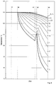
- FIG. 4 shows the calculated temperature profiles of the individual film layers A - L over time.
- the individual time steps of the calculation are plotted on the abscissa, while the ordinate shows the temperature T.
- the temperature of all layers A - L of film 1 is constant at one assumed processing temperature of e.g. 130 ° C. This presents the situation Inlet into the cooling device 3.
- the temperature distribution over the thickness of the film 1 shows no differences. The film is completely and uniformly warmed.
- the cooling device 3 already has the film 1 from the inside cooled.
- Layer L only has a temperature of approx. 120 ° C, while on the Outside of layer A there is still a constant processing temperature of 130 ° C.
- the film 1 is on the Inside (layer L) cooled further. There is already one on the outside (layer A) slight temperature drop.
- the temperature is the slide 1 has increased somewhat overall. This is because between that Time t3, i.e. leaving the cooling device 3, and the time t4, i.e. the Accumulation on the deflection roller 5, due to the ambient conditions 2, in the example 130 ° C, the film 1 is briefly supplied with heat again. In addition, it is due the heat flow within the film 1 to compensate for the warmer to the colder come.
- the temperature of the sealing Layer L greatly reduced so that it does not stick to the deflecting roller 5 comes.
- Time t5 shows the temperature of the film 1 when it leaves the deflection roller 5 the deflection roller 5, cooled to approximately 25 ° C., is the temperature of the film 1 overall decreased, especially the temperature of the contact with the guide roller coming sealing layer L has dropped sharply.
- the required cooling capacity of the cooling device 3 must be selected so that the Entry of the film 1 into the cooling device 3 until the film 1 runs onto the Deflection roller 5, the temperature of the boundary layer L is reduced so far that its Sealing temperature is fallen below. This is with the help of the air speed Air temperature, the length of the blow box and the distance of the nozzles 4 to the film 1 possible.
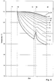
- FIG. 5 shows the calculated time profile of the temperature of the different layers A - L of the film 1.
- the individual layers A - L can be seen on the abscissa.
- the temperature T is again plotted on the ordinate.
- the diagram thus shows the temperature profile within the film at different positions and times t1, t3, t4 and t5 shown in FIG.
- the film is completely warmed and has a processing temperature of e.g. B. 130 ° C.
- time t3 when leaving the cooling device 3 the temperature on the cooled side is greatly reduced, while on the opposite side there is still almost the starting temperature.
- the Cooling device 3 to the smallest possible distance between the Blow device 3 and the deflecting roller 5.
- the shorter the distance the shorter the temperature rise of the film 1 also fails in this area.
- excessive cooling of the deflecting roller e.g. to 25 ° C
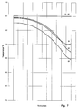
- that Temperature level of the entire film strongly influenced. It was found that a Deflection roll temperature is sufficient, which is slightly, for example 5 ° C, below the The sealing temperature of the layer L is around a sticking of the film 1 with the deflecting roller 5 to avoid. This is shown in Figures 6 and 7.
- Figures 6 and 7 correspond to Figures 4 and 5, only here Deflection roll temperature to z. B. 90 ° C was raised. You can see that the inner Layer L of the film is still sufficiently below the temperature Sealing temperature is cooled while the overall temperature is within the film runs more evenly.
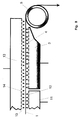
- Figure 8 shows a further embodiment of the invention.
- the outer layer that is, the layer of film 1 opposite the sealing layer
- one Heating device 13 associated with blow nozzles 14 that heat the outside of the film 1 feeds while the inside is cooled by the cooling device 3. This will the decrease in the average temperature of the film is minimized, since the film is constantly Outside heat is supplied.
- Such a heater could also around Deflection roller are arranged around and apply heat to the outside of the film 1.
- a heating device 11 with air nozzles 12 can also be used be arranged, which supplies heat to the inside of the film 1 and this up to Cooling device 3 holds at processing temperature.
Landscapes
- Engineering & Computer Science (AREA)
- Mechanical Engineering (AREA)
- Physics & Mathematics (AREA)
- Thermal Sciences (AREA)
- Lining Or Joining Of Plastics Or The Like (AREA)
- Package Closures (AREA)
- Extrusion Moulding Of Plastics Or The Like (AREA)
- Laminated Bodies (AREA)
- Processing And Handling Of Plastics And Other Materials For Molding In General (AREA)
Abstract
Description
Typische Verarbeitungstemperaturen liegen dabei zwischen 80 °C und 220 °C. Siegelfähige Schichten werden typischerweise bei Temperaturen von derzeit 100 - 140 °C aktiviert. Die Tendenz geht jedoch hin zu immer niedrigeren Temperaturen. So werden derzeit Polymere für die Siegelschichten erprobt mit Siegeltemperaturen von 70 - 80 °C Die großen Temperaturunterschiede zwischen Verarbeitungstemperaturen und Siegeltemperaturen führen in den Verarbeitungsmaschinen - speziell bei Heiz- und Umlenkwalzen - zu Problemen. Es kommt bei Walzen mit Oberflächentemperaturen, die über der Siegeltemperatur liegen, zum Verkleben und damit zum Zerstören der siegelfähigen Schicht. Darüber hinaus kann dies zu Betriebsstörungen führen, die einen Stillstand der Anlage erfordern.
Wichtig ist, dass durch die Kühleinrichtung das Temperaturniveau der gesamten Folie nicht zu sehr abgesenkt wird, sondern im wesentlichen nur die äußere kritische Schicht betroffen ist. Gestaltet man die Kühleinrichtung so, dass ein hoher Wärmeübergang auf möglichst kurzer Strecke erreicht wird, verhindert die relativ schlechte Wärmeleitfähigkeit der Polymere ein zu starkes Vordringen der Abkühlung innerhalb der Folienschichten. Andererseits erreicht man durch den hohen Wärmeübergang eine ausreichendes Abkühlen der siegelfähigen Schicht vor Auflaufen auf die Umlenk- oder Führungswalzen.
- Figur 1:
- einen schematischen Ausschnitt aus einer
Folienverarbeitungsanlage mit erfindungsgemäßer Kühleinrichtung; - Figur 2:
- den Ausschnitt gemäß Figur 1 mit einer Darstellung verschiedener Verarbeitungszeitpunkte;
- Figur 3:
- einen schematischen Querschnitt durch eine Mehrschicht-Kunststofffolie mit Unterteilung in verschiedene Schichten A-L;
- Figur 4:
- eine Darstellung eines berechneten Temperaturverlaufs in den einzelnen Schichten A-L über der Zeit bei stark gekühlter Umlenkwalze;
- Figur 5:
- eine Darstellung der berechneten Temperatur in den einzelnen Schichten A-L zu bestimmten Zeitpunkten bei stark gekühlter Umlenkwalze;
- Figur 6:
- eine Darstellung eines berechneten Temperaturverlaufs in den einzelnen Schichten A-L über der Zeit bei wenig gekühlter Umlenkwalze;
- Figur 7:
- eine Darstellung der berechneten Temperatur in den einzelnen Schichten A-L zu bestimmten Zeitpunkten bei wenig gekühlter Umlenkwalze;
- Figur 8:
- eine weitere Ausgestaltung der Erfindung mit zusätzlicher Heizeinrichtung.
Auf der Abszisse sind die einzelnen Zeitschritte der Berechnung aufgetragen, während die Ordinate die Temperatur T zeigt. Es wird insbesondere auf die in Figur 2 gezeigten Zeitpunkte t1 - t 5 Bezug genommen.
Zum Zeitpunkt t1 ist die Folie vollständig durchgewärmt und hat eine Verarbeitungstemperatur von z. B. 130°C.
Zum Zeitpunkt t3 beim Verlassen der Kühleinrichtung 3 ist die Temperatur auf der gekühlten Seite stark herabgesetzt, während auf der gegenüber liegenden Seite noch nahezu die Ausgangstemperatur vorliegt. Anschließend beim Übergang von der Kühleinrichtung 3 zur Umlenkwalze 5 (Zeitpunkt t4) gleicht sich die Temperatur innerhalb der Folie etwas aus und steigt insbesondere in den inneren Schichten K und L aufgrund der Umgebungstemperatur von 130 °C wieder etwas an. Dann im Zeitpunkt t5, mit dem Kontakt an der gekühlten Umlenkwalze 5, deren Temperatur in diesem Fall rechnerisch mit 25 °C angenommen wurde, fällt die Temperatur der Folie 1 an der inneren Schicht L stark auf unter 80°C ab. An der Außenseite (Schicht A) bleibt die Temperatur bei nahezu 126 °C stehen.
- 1
- Mehrschicht-Kunststofffolie
- 2
- Umgebungstemperatur (Tu)
- 3
- Kühleinrichtung
- 4
- Luftdüsen
- 5
- Umlenkwalze
- 6
- Gebläse
- 7
- Luftkühler
- 8
- Pumpe
- 9
- Wasserkühler
- 10
- Folienlaufrichtung
- 11
- Heizeinrichtung
- 12
- Lüftdüsen
- 13
- Heizeinrichtung
- 14
- Luftdüsen
- A - L
- Schichten der Kunststofffolie 1
- t1 - t5
- Zeitpunkte
Claims (8)
- Verfahren zur Verarbeitung von Mehrschicht-Kunststoff-Flachfolien (1) mit einer oberhalb einer bestimmten Siegeltemperatur liegenden, siegelfähigen Außenschicht (L), wobei die Kunststoff-Flachfolie vor dem Verarbeiten auf eine Verarbeitungstemperatur aufgeheizt wird und wobei die siegelfähige Außenschicht (L) der Kunststoff-Flachfolie mit mindestens einer Umlenkwalze (5) in Berührungskontakt gebracht wird,
dadurch gekennzeichnet, dass die siegelfähige Außenschicht (L) der Mehrschicht-Kunststoff-Flachfolie (1) vor dem Erreichen der Umlenkwalze auf eine Temperatur unterhalb der Siegeltemperatur abgekühlt wird, während in den übrigen Schichten der Kunststoff-Flachfolie das Niveau der Verarbeitungstemperatur weitgehend aufrecht erhalten wird. - Verfahren nach Anspruch 1,dadurch gekennzeichnet, dass zur Kühlung der siegelfähigen Schicht (L) gekühlte Luft verwendet wird.
- Verfahren nach Anspruch 1, dadurch gekennzeichnet, dass die Umlenkwalze (5) auf eine Temperatur unterhalb der Siegeltemperatur gekühlt wird.
- Verfahren nach Anspruch 1, dadurch gekennzeichnet, dass der der siegelfähigen Schicht (L) gegenüberliegenden Schicht (A) der Mehrschicht-Kunststoff-Flachfolie (1) vor dem Erreichen der Umlenkwalze (5) und/oder während des Berührungskontaktes mit der Umlenkwalze (5) Wärme zugeführt wird.
- Verfahren nach Anspruch 1, dadurch gekennzeichnet, dass die Siegeltemperatur unterhalb der Verarbeitungstemperatur liegt.
- Vorrichtung zur Verarbeitung von Mehrschicht-Kunststoff-Flachfolien (1) mit einer oberhalb einer bestimmten Siegeltemperatur liegenden, siegelfähigen Schicht (L), wobei die auf eine Verarbeitungstemperatur aufgeheizte Kunststoff-Flachfolie (1)mit mindestens einer Umlenkwalze (5) in Berührungskontakt gebracht wird,
dadurch gekennzeichnet, dass in Folientransportrichtung (10) gesehen vor der Umlenkwalze (5) eine Kaltluft abgebende Kühleinrichtung (3) vorgesehen ist, mit deren Hilfe die siegelfähige Schicht (L) vor Erreichen der Umlenkwalze (5) auf eine Temperatur unterhalb der Siegeltemperatur abgekühlt wird. - Vorrichtung nach Anspruch 6, dadurch gekennzeichnet, dass die Kühleinrichtung (3) eine Anzahl (4) von auf die siegelfähige Schicht (L) gerichteten Luftdüsen umfasst, welche gekühlte Luft auf die Schicht leiten.
- Vorrichtung nach Anspruch 6 oder 7, dadurch gekennzeichnet, dass der Kühleinrichtung (3) gegenüberliegend eine Heizeinrichtung (13) angeordnet ist.
Applications Claiming Priority (2)
| Application Number | Priority Date | Filing Date | Title |
|---|---|---|---|
| DE10149371A DE10149371A1 (de) | 2001-10-06 | 2001-10-06 | Verfahren und Vorrichtung zur Verarbeitung von Mehrschichtkunststofffolien |
| DE10149371 | 2001-10-06 |
Publications (3)
| Publication Number | Publication Date |
|---|---|
| EP1300355A2 true EP1300355A2 (de) | 2003-04-09 |
| EP1300355A3 EP1300355A3 (de) | 2004-03-31 |
| EP1300355B1 EP1300355B1 (de) | 2006-06-28 |
Family
ID=7701653
Family Applications (1)
| Application Number | Title | Priority Date | Filing Date |
|---|---|---|---|
| EP02020624A Expired - Lifetime EP1300355B1 (de) | 2001-10-06 | 2002-09-13 | Verfahren und Vorrichtung zur Verarbeitung von Mehrschichtkunststoffen |
Country Status (5)
| Country | Link |
|---|---|
| US (1) | US20030066602A1 (de) |
| EP (1) | EP1300355B1 (de) |
| JP (1) | JP3892381B2 (de) |
| AT (1) | ATE331685T1 (de) |
| DE (2) | DE10149371A1 (de) |
Families Citing this family (1)
| Publication number | Priority date | Publication date | Assignee | Title |
|---|---|---|---|---|
| US20130270739A1 (en) * | 2012-04-13 | 2013-10-17 | Miroslav Planeta | Method and apparatus for controlled shrinking of plastic sheet material |
Family Cites Families (17)
| Publication number | Priority date | Publication date | Assignee | Title |
|---|---|---|---|---|
| NL73233C (de) * | 1949-01-18 | |||
| US3318018A (en) * | 1964-12-31 | 1967-05-09 | Beloit Corp | Cooling and protective means for printed web material |
| DE1619291A1 (de) * | 1966-06-23 | 1971-06-03 | Schacht Kg F | In bekannter Weise impraegnierte und vorzugsweise mit Deckschichten versehene Dachdichtungsbahn |
| GB1371334A (en) * | 1970-10-30 | 1974-10-23 | Agfa Gevaert | Film stretching method and apparatus |
| US3985604A (en) * | 1971-11-26 | 1976-10-12 | Deering Milliken Research Corporation | Method for the manufacture of laminated packing material containing metal foil |
| DE2833189C2 (de) * | 1978-07-28 | 1984-09-20 | Brückner - Maschinenbau Gernot Brückner GmbH & Co KG, 8221 Siegsdorf | Verfahren zum Längsrecken einer zumindest zweischichtigen thermoplastischen Kunststoffolie sowie Vorrichtung zur Durchführung des Verfahrens |
| ZA795410B (en) * | 1978-12-28 | 1980-09-24 | Grace W R & Co | Improved heat sealing irradiated film |
| GB2055855A (en) * | 1979-08-07 | 1981-03-11 | Ici Ltd | Heat-treating polyolefin films |
| EP0172924B1 (de) * | 1984-08-14 | 1989-03-15 | Mitsubishi Jukogyo Kabushiki Kaisha | Vorrichtung zur Herstellung von Folien |
| US4631155A (en) * | 1985-02-01 | 1986-12-23 | American Hoechst Corporation | Process for manufacture of surface-modified oriented polymeric film |
| DE3620219A1 (de) * | 1986-06-16 | 1987-12-17 | Hoechst Ag | Verfahren zur herstellung von biaxial gestreckten folien sowie vorrichtung zur durchfuehrung des verfahrens |
| US5204182A (en) * | 1990-05-04 | 1993-04-20 | Imperial Chemical Industries Plc | Polyolefin film |
| TW200424B (de) * | 1991-09-09 | 1993-02-21 | Avery Dennison Corp | |
| US5429785A (en) * | 1994-03-01 | 1995-07-04 | E. I. Du Pont De Nemours And Company | Method of making biaxially oriented thermoplastic films |
| US5866249A (en) * | 1995-12-18 | 1999-02-02 | Minnesota Mining And Manufacturing Company | Pressure-sensitive adhesive based on partially oriented and partially crystallized elastomer |
| US6726969B1 (en) * | 1997-01-28 | 2004-04-27 | Avery Dennison Corporation | In-mold labels and uses thereof |
| DE19708886C1 (de) * | 1997-03-05 | 1998-02-12 | Dornier Gmbh Lindauer | Verfahren und Vorrichtung zum kontinuierlichen Abziehen eines Schmelzefilms aus einer Folienproduktionsanlage |
-
2001
- 2001-10-06 DE DE10149371A patent/DE10149371A1/de not_active Withdrawn
-
2002
- 2002-09-13 AT AT02020624T patent/ATE331685T1/de not_active IP Right Cessation
- 2002-09-13 DE DE50207369T patent/DE50207369D1/de not_active Expired - Lifetime
- 2002-09-13 EP EP02020624A patent/EP1300355B1/de not_active Expired - Lifetime
- 2002-10-01 JP JP2002288718A patent/JP3892381B2/ja not_active Expired - Fee Related
- 2002-10-07 US US10/267,070 patent/US20030066602A1/en not_active Abandoned
Also Published As
| Publication number | Publication date |
|---|---|
| JP3892381B2 (ja) | 2007-03-14 |
| EP1300355B1 (de) | 2006-06-28 |
| JP2003200501A (ja) | 2003-07-15 |
| DE50207369D1 (de) | 2006-08-10 |
| ATE331685T1 (de) | 2006-07-15 |
| US20030066602A1 (en) | 2003-04-10 |
| DE10149371A1 (de) | 2003-04-24 |
| EP1300355A3 (de) | 2004-03-31 |
Similar Documents
| Publication | Publication Date | Title |
|---|---|---|
| EP2952330B1 (de) | Blasfolienanlage und verfahren zum herstellen einer blasfolienbahn | |
| EP2559546B1 (de) | Verfahren und Vorrichtung zum Herstellen einer Folie aus thermoplastischem Kunststoff, sowie damit hergestellte Folie | |
| EP3057770B1 (de) | Verfahren zum herstellen einer blasfolienbahn sowie blasfolienanlage | |
| EP3919422B1 (de) | Folienwickelsystem und verbund aus einer folienreckanlage und einem solchen folienwickelsystem | |
| EP0461488A2 (de) | Verfahren zur Herstellung von geglätteten extrudierten Vollplatten oder Folien aus thermoplastischem Kunststoff | |
| CH618936A5 (de) | ||
| EP0485896B1 (de) | Vorrichtung und Verfahren zum Herstellen eines mehrschichtigen Folienverbundes | |
| WO2016012182A1 (de) | Vorrichtung und verfahren zur herstellung von verbundblechen durch mehrfachkaschierung | |
| EP2809496A1 (de) | Reckwerk und verfahren zum längen einer folienbahn | |
| EP0546311A1 (de) | Vorrichtung und Verfahren zum Herstellen eines mehrschichtigen Folienverbundes | |
| DE2712436A1 (de) | Verfahren zur herstellung von biaxial molekular orientierten polymerfilmen | |
| DE3620219A1 (de) | Verfahren zur herstellung von biaxial gestreckten folien sowie vorrichtung zur durchfuehrung des verfahrens | |
| EP3520989A1 (de) | Verfahren und vorrichtung zur herstellung einer kunststoff-folie | |
| EP1300355B1 (de) | Verfahren und Vorrichtung zur Verarbeitung von Mehrschichtkunststoffen | |
| DE69829060T2 (de) | Verfahren und Vorrichtung zum Beschichten eines metallischen bandförmigen Substrats mit einem Kunststoffband | |
| EP1270214B1 (de) | Verfahren zur Beschichtung der Oberfläche eines Metallbandes mit einem Kunststofffilm | |
| EP1737641B1 (de) | Vorrichtung zum transport eines folienschlauches | |
| WO2021074240A1 (de) | Verfahren und folienreckanlage zur herstellung siegelfähiger biaxial orientierter polyesterbasierter folie | |
| EP1883525B1 (de) | Verfahren zum querverstrecken einer materialbahn | |
| WO2017215731A1 (de) | Basisstruktur, vorrichtung und verfahren zum transport von folie | |
| WO2022161584A1 (de) | Blasfolienanlage und verfahren zum betreiben einer blasfolienanlage | |
| DE60024397T2 (de) | Verfahren zur doppelten Orientierung von mehrschichtigen, thermoplastischen Materialien | |
| DE1504443C (de) | Verfahren zur Verbesserung der physikalischen Eigenschaften von Kunststofffolienbahnen | |
| DE102006012417A1 (de) | Vorrichtung zur Regulierung der Folientemperatur in einer Folien-Fertigungsanlage, Folien-Fertigungsanlage mit einer solchen Vorrichtung, diesbezügliches Verfahren, sowie Verwendung der Vorrichtung zur Regulierung der Folientemperatur | |
| DE1817248A1 (de) | Verfahren zur Herstellung von biaxial vorgedehnter Folie aus thermoplastischem Kunststoff sowie Vorrichtung zur Ausuebung dieses Verfahrens |
Legal Events
| Date | Code | Title | Description |
|---|---|---|---|
| PUAI | Public reference made under article 153(3) epc to a published international application that has entered the european phase |
Free format text: ORIGINAL CODE: 0009012 |
|
| AK | Designated contracting states |
Designated state(s): AT BE BG CH CY CZ DE DK EE ES FI FR GB GR IE IT LI LU MC NL PT SE SK TR Kind code of ref document: A2 Designated state(s): AT BE BG CH CY CZ DE DK EE ES FI FR GB GR IE IT LI LU MC NL PT SE SK TR |
|
| AX | Request for extension of the european patent |
Extension state: AL LT LV MK RO SI |
|
| PUAL | Search report despatched |
Free format text: ORIGINAL CODE: 0009013 |
|
| AK | Designated contracting states |
Kind code of ref document: A3 Designated state(s): AT BE BG CH CY CZ DE DK EE ES FI FR GB GR IE IT LI LU MC NL PT SE SK TR |
|
| AX | Request for extension of the european patent |
Extension state: AL LT LV MK RO SI |
|
| 17P | Request for examination filed |
Effective date: 20040615 |
|
| 17Q | First examination report despatched |
Effective date: 20041103 |
|
| AKX | Designation fees paid |
Designated state(s): AT BE BG CH CY CZ DE DK EE ES FI FR GB GR IE IT LI LU MC NL PT SE SK TR |
|
| GRAP | Despatch of communication of intention to grant a patent |
Free format text: ORIGINAL CODE: EPIDOSNIGR1 |
|
| GRAS | Grant fee paid |
Free format text: ORIGINAL CODE: EPIDOSNIGR3 |
|
| GRAA | (expected) grant |
Free format text: ORIGINAL CODE: 0009210 |
|
| AK | Designated contracting states |
Kind code of ref document: B1 Designated state(s): AT BE BG CH CY CZ DE DK EE ES FI FR GB GR IE IT LI LU MC NL PT SE SK TR |
|
| PG25 | Lapsed in a contracting state [announced via postgrant information from national office to epo] |
Ref country code: SK Free format text: LAPSE BECAUSE OF FAILURE TO SUBMIT A TRANSLATION OF THE DESCRIPTION OR TO PAY THE FEE WITHIN THE PRESCRIBED TIME-LIMIT Effective date: 20060628 Ref country code: NL Free format text: LAPSE BECAUSE OF FAILURE TO SUBMIT A TRANSLATION OF THE DESCRIPTION OR TO PAY THE FEE WITHIN THE PRESCRIBED TIME-LIMIT Effective date: 20060628 Ref country code: GB Free format text: LAPSE BECAUSE OF FAILURE TO SUBMIT A TRANSLATION OF THE DESCRIPTION OR TO PAY THE FEE WITHIN THE PRESCRIBED TIME-LIMIT Effective date: 20060628 Ref country code: FI Free format text: LAPSE BECAUSE OF FAILURE TO SUBMIT A TRANSLATION OF THE DESCRIPTION OR TO PAY THE FEE WITHIN THE PRESCRIBED TIME-LIMIT Effective date: 20060628 Ref country code: IE Free format text: LAPSE BECAUSE OF FAILURE TO SUBMIT A TRANSLATION OF THE DESCRIPTION OR TO PAY THE FEE WITHIN THE PRESCRIBED TIME-LIMIT Effective date: 20060628 |
|
| REG | Reference to a national code |
Ref country code: GB Ref legal event code: FG4D Free format text: NOT ENGLISH |
|
| REG | Reference to a national code |
Ref country code: CH Ref legal event code: EP |
|
| REG | Reference to a national code |
Ref country code: IE Ref legal event code: FG4D Free format text: LANGUAGE OF EP DOCUMENT: GERMAN |
|
| REF | Corresponds to: |
Ref document number: 50207369 Country of ref document: DE Date of ref document: 20060810 Kind code of ref document: P |
|
| PG25 | Lapsed in a contracting state [announced via postgrant information from national office to epo] |
Ref country code: SE Free format text: LAPSE BECAUSE OF FAILURE TO SUBMIT A TRANSLATION OF THE DESCRIPTION OR TO PAY THE FEE WITHIN THE PRESCRIBED TIME-LIMIT Effective date: 20060928 Ref country code: DK Free format text: LAPSE BECAUSE OF FAILURE TO SUBMIT A TRANSLATION OF THE DESCRIPTION OR TO PAY THE FEE WITHIN THE PRESCRIBED TIME-LIMIT Effective date: 20060928 |
|
| PG25 | Lapsed in a contracting state [announced via postgrant information from national office to epo] |
Ref country code: BE Free format text: LAPSE BECAUSE OF NON-PAYMENT OF DUE FEES Effective date: 20060930 Ref country code: LI Free format text: LAPSE BECAUSE OF NON-PAYMENT OF DUE FEES Effective date: 20060930 Ref country code: CH Free format text: LAPSE BECAUSE OF NON-PAYMENT OF DUE FEES Effective date: 20060930 Ref country code: MC Free format text: LAPSE BECAUSE OF NON-PAYMENT OF DUE FEES Effective date: 20060930 |
|
| PG25 | Lapsed in a contracting state [announced via postgrant information from national office to epo] |
Ref country code: ES Free format text: LAPSE BECAUSE OF FAILURE TO SUBMIT A TRANSLATION OF THE DESCRIPTION OR TO PAY THE FEE WITHIN THE PRESCRIBED TIME-LIMIT Effective date: 20061009 |
|
| PG25 | Lapsed in a contracting state [announced via postgrant information from national office to epo] |
Ref country code: PT Free format text: LAPSE BECAUSE OF FAILURE TO SUBMIT A TRANSLATION OF THE DESCRIPTION OR TO PAY THE FEE WITHIN THE PRESCRIBED TIME-LIMIT Effective date: 20061128 |
|
| NLV1 | Nl: lapsed or annulled due to failure to fulfill the requirements of art. 29p and 29m of the patents act | ||
| GBV | Gb: ep patent (uk) treated as always having been void in accordance with gb section 77(7)/1977 [no translation filed] |
Effective date: 20060628 |
|
| ET | Fr: translation filed | ||
| REG | Reference to a national code |
Ref country code: IE Ref legal event code: FD4D |
|
| PLBE | No opposition filed within time limit |
Free format text: ORIGINAL CODE: 0009261 |
|
| STAA | Information on the status of an ep patent application or granted ep patent |
Free format text: STATUS: NO OPPOSITION FILED WITHIN TIME LIMIT |
|
| REG | Reference to a national code |
Ref country code: CH Ref legal event code: PL |
|
| 26N | No opposition filed |
Effective date: 20070329 |
|
| BERE | Be: lapsed |
Owner name: LINDAUER DORNIER G.- M.B.H Effective date: 20060930 |
|
| PG25 | Lapsed in a contracting state [announced via postgrant information from national office to epo] |
Ref country code: GR Free format text: LAPSE BECAUSE OF FAILURE TO SUBMIT A TRANSLATION OF THE DESCRIPTION OR TO PAY THE FEE WITHIN THE PRESCRIBED TIME-LIMIT Effective date: 20060929 |
|
| PG25 | Lapsed in a contracting state [announced via postgrant information from national office to epo] |
Ref country code: BG Free format text: LAPSE BECAUSE OF FAILURE TO SUBMIT A TRANSLATION OF THE DESCRIPTION OR TO PAY THE FEE WITHIN THE PRESCRIBED TIME-LIMIT Effective date: 20060928 Ref country code: EE Free format text: LAPSE BECAUSE OF FAILURE TO SUBMIT A TRANSLATION OF THE DESCRIPTION OR TO PAY THE FEE WITHIN THE PRESCRIBED TIME-LIMIT Effective date: 20060628 |
|
| PG25 | Lapsed in a contracting state [announced via postgrant information from national office to epo] |
Ref country code: LU Free format text: LAPSE BECAUSE OF NON-PAYMENT OF DUE FEES Effective date: 20060913 |
|
| PG25 | Lapsed in a contracting state [announced via postgrant information from national office to epo] |
Ref country code: CY Free format text: LAPSE BECAUSE OF FAILURE TO SUBMIT A TRANSLATION OF THE DESCRIPTION OR TO PAY THE FEE WITHIN THE PRESCRIBED TIME-LIMIT Effective date: 20060628 |
|
| PGFP | Annual fee paid to national office [announced via postgrant information from national office to epo] |
Ref country code: CZ Payment date: 20080728 Year of fee payment: 7 Ref country code: IT Payment date: 20080911 Year of fee payment: 7 |
|
| PGFP | Annual fee paid to national office [announced via postgrant information from national office to epo] |
Ref country code: TR Payment date: 20080806 Year of fee payment: 7 |
|
| PGFP | Annual fee paid to national office [announced via postgrant information from national office to epo] |
Ref country code: AT Payment date: 20090907 Year of fee payment: 8 |
|
| PGFP | Annual fee paid to national office [announced via postgrant information from national office to epo] |
Ref country code: DE Payment date: 20090730 Year of fee payment: 8 |
|
| PG25 | Lapsed in a contracting state [announced via postgrant information from national office to epo] |
Ref country code: CZ Free format text: LAPSE BECAUSE OF NON-PAYMENT OF DUE FEES Effective date: 20090913 |
|
| PG25 | Lapsed in a contracting state [announced via postgrant information from national office to epo] |
Ref country code: IT Free format text: LAPSE BECAUSE OF NON-PAYMENT OF DUE FEES Effective date: 20090913 |
|
| REG | Reference to a national code |
Ref country code: FR Ref legal event code: ST Effective date: 20110531 |
|
| REG | Reference to a national code |
Ref country code: DE Ref legal event code: R119 Ref document number: 50207369 Country of ref document: DE Effective date: 20110401 |
|
| PG25 | Lapsed in a contracting state [announced via postgrant information from national office to epo] |
Ref country code: FR Free format text: LAPSE BECAUSE OF NON-PAYMENT OF DUE FEES Effective date: 20100930 Ref country code: DE Free format text: LAPSE BECAUSE OF NON-PAYMENT OF DUE FEES Effective date: 20110401 |
|
| PG25 | Lapsed in a contracting state [announced via postgrant information from national office to epo] |
Ref country code: AT Free format text: LAPSE BECAUSE OF NON-PAYMENT OF DUE FEES Effective date: 20100913 |
|
| PGFP | Annual fee paid to national office [announced via postgrant information from national office to epo] |
Ref country code: FR Payment date: 20091002 Year of fee payment: 8 |
|
| PG25 | Lapsed in a contracting state [announced via postgrant information from national office to epo] |
Ref country code: TR Free format text: LAPSE BECAUSE OF NON-PAYMENT OF DUE FEES Effective date: 20090913 |