EP1300367A2 - Station d'épuration des eaux usées compactes - Google Patents
Station d'épuration des eaux usées compactes Download PDFInfo
- Publication number
- EP1300367A2 EP1300367A2 EP02022120A EP02022120A EP1300367A2 EP 1300367 A2 EP1300367 A2 EP 1300367A2 EP 02022120 A EP02022120 A EP 02022120A EP 02022120 A EP02022120 A EP 02022120A EP 1300367 A2 EP1300367 A2 EP 1300367A2
- Authority
- EP
- European Patent Office
- Prior art keywords
- clarification chamber
- chamber
- clarification
- water
- primary
- Prior art date
- Legal status (The legal status is an assumption and is not a legal conclusion. Google has not performed a legal analysis and makes no representation as to the accuracy of the status listed.)
- Withdrawn
Links
Images
Classifications
-
- C—CHEMISTRY; METALLURGY
- C02—TREATMENT OF WATER, WASTE WATER, SEWAGE, OR SLUDGE
- C02F—TREATMENT OF WATER, WASTE WATER, SEWAGE, OR SLUDGE
- C02F3/00—Biological treatment of water, waste water, or sewage
- C02F3/02—Aerobic processes
- C02F3/12—Activated sludge processes
- C02F3/1236—Particular type of activated sludge installations
- C02F3/1242—Small compact installations for use in homes, apartment blocks, hotels or the like
- C02F3/1247—Small compact installations for use in homes, apartment blocks, hotels or the like comprising circular tanks with elements, e.g. decanters, aeration basins, in the form of segments, crowns or sectors
-
- Y—GENERAL TAGGING OF NEW TECHNOLOGICAL DEVELOPMENTS; GENERAL TAGGING OF CROSS-SECTIONAL TECHNOLOGIES SPANNING OVER SEVERAL SECTIONS OF THE IPC; TECHNICAL SUBJECTS COVERED BY FORMER USPC CROSS-REFERENCE ART COLLECTIONS [XRACs] AND DIGESTS
- Y02—TECHNOLOGIES OR APPLICATIONS FOR MITIGATION OR ADAPTATION AGAINST CLIMATE CHANGE
- Y02A—TECHNOLOGIES FOR ADAPTATION TO CLIMATE CHANGE
- Y02A20/00—Water conservation; Efficient water supply; Efficient water use
- Y02A20/20—Controlling water pollution; Waste water treatment
- Y02A20/208—Off-grid powered water treatment
-
- Y—GENERAL TAGGING OF NEW TECHNOLOGICAL DEVELOPMENTS; GENERAL TAGGING OF CROSS-SECTIONAL TECHNOLOGIES SPANNING OVER SEVERAL SECTIONS OF THE IPC; TECHNICAL SUBJECTS COVERED BY FORMER USPC CROSS-REFERENCE ART COLLECTIONS [XRACs] AND DIGESTS
- Y02—TECHNOLOGIES OR APPLICATIONS FOR MITIGATION OR ADAPTATION AGAINST CLIMATE CHANGE
- Y02W—CLIMATE CHANGE MITIGATION TECHNOLOGIES RELATED TO WASTEWATER TREATMENT OR WASTE MANAGEMENT
- Y02W10/00—Technologies for wastewater treatment
- Y02W10/10—Biological treatment of water, waste water, or sewage
Definitions
- the invention relates to a device for treating waste water in one Multi-chamber small wastewater treatment plant with at least one pre-treatment chamber and one Clarification chamber, which are separated by a partition, with an aerator inside the clarification chamber and pumping devices for transferring dirty water from the primary clarifier to the clarifier and for the return of Excess sludge from the clarifier to the primary clarifier.
- the invention is therefore based on the object, a clarifying device of the above Way of creating a more effective and faster implementation of the clarification process permitted without the need for additional technical units are.
- the dirty water is forced out of the pre-clarification chamber into the clarifier at a higher speed than the one before described system that relies on the action of gravity.
- This is essential, since a higher conveying speed is necessary in this direction than returning the limited amount of excess sludge.
- this is done according to the system of communicating Tubing after the line is filled at the end of a pumping process from the clarification chamber filled above the water level in the primary clarification chamber a suction effect is exerted in the direction of the primary clarification chamber.
- it is possible to close the clarification chamber to almost any Fill level. It is Z. B. possible, the sewage treatment plant until reaching a operating maximum levels in the clarifier in an economy mode and only then start the actual cleaning operation.
- the pump on the side of the pre-clarification chamber is targeted and quick Filling the clarifier always guaranteed.
- the pre-clarifier can be irregular Inflow can be used as a buffer tank from which the clarification chamber with the help of the pump in connection with a suitable control system can be. Because the amount of water pumped out of the primary clarifier is greater than it would be possible with a simple level compensation Another advantage is a considerable increase in the buffer volume the pre-clarification chamber.
- the pump provided according to the invention offers the further Advantage that they also for the controlled return of the excess sludge can be used from the clarifier to the primary clarifier. Since the pump outlet line is immersed in the clarification chamber, the water can or the excess sludge from the clarification chamber after switching off the Pumping process according to the principle of communicating tubes into the primary clarification chamber running back.
- a downwardly open shell is provided, which the inlet opening of the Line surrounds, but leaves free. Because the submersible aerator air is in the area below the shell presses, the air bubbles emitted by the submersible aerator collect in the shell and thus also in the line. Once there is a sufficient has formed a large air cushion, the suction effect in the direction of the primary clarification chamber interrupted.
- the associated control can be designed so that at the beginning of a clarification cycle Dirty water is transferred from the primary clarifier to the clarifier becomes. If the pump is now switched off, a water-sludge mixture flows from the clarifier back to the primary clarifier. This backflow can be in be interrupted as described if the aerator has a pre-programmed Time interval switched on or also for the further clarification process is put into operation. As soon as there is sufficient air cushion in the Output line of the pump has collected, the backflow is ended. The Clarification process can continue.
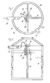
- Fig. 1 shows a cross section through a so-called three-chamber pit, the one has cylindrical container 10, which by a first partition 12 in two equal halves is divided, one by another partition 14 is halved again.
- a clarification chamber is created 16 with a circumferential angle of 180 ° and two pre-clarification chambers with 18.20 Circumferential angles of 90 °, which are connected to each other and the function a sludge storage, buffer and sedimentation basin.
- Wastewater will passed through an inlet 22 into one of the primary settling tanks 20. Clarified water exits the clarification chamber 16 through an outlet 24.
- Such three-chamber pits have previously been used as clarifiers, are therefore already present and are intended to be provided by those according to the invention Units can be retrofitted.
- a Frame or a bracket 26 are used on the various units are attached so that the entire retrofit kit on one of the partitions, in the example shown, the long partition 12 can be hung.
- the units individually on the partitions or to mount on floats.
- Clear water extraction pump 28 is attached using a hose 30 the drain 24 is connected and releases clarified water to the outside.
- the clear water extraction pump 28 is an aerator 32, the one from the outside, only partially shown hose absorbs outside air and in a strong pump jet down into the clarifier water suppressed. This creates air bubbles in the water that rise upwards and cause oxygen to enter the water.
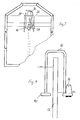
- a further pump 36 which is on her Output is connected to a line 38 which is arcuate over the partition 12 is guided into the clarification chamber 16.
- This pump 36 with the line 38 are shown enlarged in FIG. 4.
- the pump 36 serves the waste water, that has collected in the pre-clarification chambers 18, 20 via the partition 12 to be transferred into the clarification chamber 16.
- a collecting tray 40 open at the bottom.
- the aerator 32 is below of the aerator and thus also below the drip tray 40 in the water formed a large area in which air bubbles rise.
- the clarification chamber 16 and the pre-clarification chamber 18 can also be formed by separate containers. The "partition" between them is then through parts of the walls of each container educated.
Landscapes
- Life Sciences & Earth Sciences (AREA)
- Biodiversity & Conservation Biology (AREA)
- Microbiology (AREA)
- Hydrology & Water Resources (AREA)
- Engineering & Computer Science (AREA)
- Environmental & Geological Engineering (AREA)
- Water Supply & Treatment (AREA)
- Chemical & Material Sciences (AREA)
- Organic Chemistry (AREA)
- Treatment Of Biological Wastes In General (AREA)
Applications Claiming Priority (2)
| Application Number | Priority Date | Filing Date | Title |
|---|---|---|---|
| DE20116397U | 2001-10-05 | ||
| DE20116397U DE20116397U1 (de) | 2001-10-05 | 2001-10-05 | Vorrichtung zur Behandlung von Abwasser |
Publications (2)
| Publication Number | Publication Date |
|---|---|
| EP1300367A2 true EP1300367A2 (fr) | 2003-04-09 |
| EP1300367A3 EP1300367A3 (fr) | 2004-02-11 |
Family
ID=7962559
Family Applications (1)
| Application Number | Title | Priority Date | Filing Date |
|---|---|---|---|
| EP02022120A Withdrawn EP1300367A3 (fr) | 2001-10-05 | 2002-10-02 | Station d'épuration des eaux usées compactes |
Country Status (3)
| Country | Link |
|---|---|
| EP (1) | EP1300367A3 (fr) |
| DE (1) | DE20116397U1 (fr) |
| HU (1) | HUP0203373A2 (fr) |
Cited By (3)
| Publication number | Priority date | Publication date | Assignee | Title |
|---|---|---|---|---|
| EP1650169A1 (fr) * | 2004-10-05 | 2006-04-26 | Markus Baumann | Dispositif de clarification biologique avec une pompe immergée |
| DE202006015834U1 (de) * | 2006-10-16 | 2008-02-21 | Atb Umwelttechnologien Gmbh | Saugvorrichtung |
| EP2628712A1 (fr) * | 2012-02-20 | 2013-08-21 | Sapling sp. z o. o. | Station d'épuration adiabatique, mécanique et biologique des eaux usées |
Families Citing this family (1)
| Publication number | Priority date | Publication date | Assignee | Title |
|---|---|---|---|---|
| DE102020132301A1 (de) | 2020-12-04 | 2022-06-09 | Kordes Kld Wasser- Und Abwassersysteme Gmbh | Abwasserbehandlungsanlage |
Family Cites Families (4)
| Publication number | Priority date | Publication date | Assignee | Title |
|---|---|---|---|---|
| GB2317168B (en) * | 1996-09-12 | 1998-11-04 | Balmoral Group | Sequential batch reactor |
| DE19812397B4 (de) * | 1998-03-20 | 2015-04-02 | Ökoservice Gesellschaft Für Umweltanalytik Und Kläranlagenbetreuung Mbh | Vollbiologische Kleinkläranlage mit zwei belüfteten Belebungsbecken |
| DE19907980C2 (de) * | 1999-02-25 | 2002-09-05 | Markus Baumann | Integrierte Vorrichtung zum Behandeln von Abwasser in Kleinkläranlagen, insbesondere Einbecken-Kläranlagen |
| DE20005909U1 (de) * | 2000-03-30 | 2001-08-09 | Boller, Reinhard, Dipl.-Ing., 57234 Wilnsdorf | Kläranlage zur Reinigung von Abwasser |
-
2001
- 2001-10-05 DE DE20116397U patent/DE20116397U1/de not_active Expired - Lifetime
-
2002
- 2002-10-02 EP EP02022120A patent/EP1300367A3/fr not_active Withdrawn
- 2002-10-04 HU HU0203373A patent/HUP0203373A2/hu unknown
Cited By (3)
| Publication number | Priority date | Publication date | Assignee | Title |
|---|---|---|---|---|
| EP1650169A1 (fr) * | 2004-10-05 | 2006-04-26 | Markus Baumann | Dispositif de clarification biologique avec une pompe immergée |
| DE202006015834U1 (de) * | 2006-10-16 | 2008-02-21 | Atb Umwelttechnologien Gmbh | Saugvorrichtung |
| EP2628712A1 (fr) * | 2012-02-20 | 2013-08-21 | Sapling sp. z o. o. | Station d'épuration adiabatique, mécanique et biologique des eaux usées |
Also Published As
| Publication number | Publication date |
|---|---|
| EP1300367A3 (fr) | 2004-02-11 |
| HUP0203373A2 (hu) | 2003-07-28 |
| DE20116397U1 (de) | 2002-01-24 |
| HU0203373D0 (en) | 2002-12-28 |
Similar Documents
| Publication | Publication Date | Title |
|---|---|---|
| EP2641876B1 (fr) | Dispositif de traitement biologique des eaux usées | |
| DE102014015488B4 (de) | Zweifunktionaler Druckluftheber für biologische Kläranlagen, Verfahren zu dessen Betrieb und dessen Verwendung | |
| EP0732457B1 (fr) | Procédé et dispositif de récupération d'eau usagée | |
| DE2733044A1 (de) | Verbesserte anlage zur abwasserbehandlung | |
| DE202008003062U1 (de) | Biologische Klärvorrichtung | |
| DE2231172A1 (de) | Kombinierte einrichtung zur biologischen abwasserreinigung | |
| EP1031540B1 (fr) | Appareil de traitement de l'eau | |
| EP1650169B1 (fr) | Dispositif de clarification biologique avec une pompe immergée | |
| EP1300367A2 (fr) | Station d'épuration des eaux usées compactes | |
| EP2284128B1 (fr) | Procédé et dispositif de nettoyage d'eaux usées et dispositif de séparation correspondant | |
| DE69227243T2 (de) | Abwasserschacht oder kleine Abwasserreinigungsanlage | |
| EP1559686B1 (fr) | Clarificateur avec un dispositif de sortie pour l'eau clarifiée | |
| DE20105661U1 (de) | Kleinkläranlage | |
| EP1110915A2 (fr) | Dispositif et procédé d épuration biologique d eaux usées | |
| WO2007090651A1 (fr) | Dispositif de pompe destiné au pompage des eaux usées | |
| DE9320600U1 (de) | Vorrichtung zur Entnahme von geklärtem Abwasser aus Rundbecken | |
| DE19541940C2 (de) | Abwasserbelebungsanlage zur biologischen Klärung von Abwässern | |
| EP3135636B1 (fr) | Station d'epuration | |
| DE19816900C1 (de) | Vorrichtung zum Sammeln und Abgeben eines vorbestimmten Flüssigkeitsvolumens | |
| DE20005896U1 (de) | Vorrichtung zum Abziehen von gereinigtem Wasser aus einem Behälter bei der biologischen Reinigung von Abwasser | |
| WO1999057068A1 (fr) | Installation d'epuration d'immeuble entierement biologique | |
| DE2348175B2 (de) | Trennbecken zum Trennen von Feststoffen und Flüssigkeiten | |
| EP1629881A1 (fr) | Station d'épuration d'eau avec filtration par membrane | |
| DE2510761A1 (de) | Vorrichtung zum reinigen von oel oder dergleichen kohlenwasserstoffe mitfuehrendem wasser | |
| DE102006043468B4 (de) | Vorrichtung zur Verhinderung von Geruchsentwicklungen und zur Verbesserung der Ölabscheidung bei nach dem Phasentrennprinzip arbeitenden Ölabscheideanlagen |
Legal Events
| Date | Code | Title | Description |
|---|---|---|---|
| PUAI | Public reference made under article 153(3) epc to a published international application that has entered the european phase |
Free format text: ORIGINAL CODE: 0009012 |
|
| AK | Designated contracting states |
Kind code of ref document: A2 Designated state(s): AT BE BG CH CY CZ DE DK EE ES FI FR GB GR IE IT LI LU MC NL PT SE SK TR Designated state(s): AT BE BG CH CY CZ DE DK EE ES FI FR GB GR IE IT LI LU MC NL PT SE SK TR |
|
| AX | Request for extension of the european patent |
Extension state: AL LT LV MK RO SI |
|
| PUAL | Search report despatched |
Free format text: ORIGINAL CODE: 0009013 |
|
| AK | Designated contracting states |
Kind code of ref document: A3 Designated state(s): AT BE BG CH CY CZ DE DK EE ES FI FR GB GR IE IT LI LU MC NL PT SE SK TR |
|
| AX | Request for extension of the european patent |
Extension state: AL LT LV MK RO SI |
|
| RIC1 | Information provided on ipc code assigned before grant |
Ipc: 7C 02F 3/00 B Ipc: 7C 02F 3/12 A |
|
| 17P | Request for examination filed |
Effective date: 20040108 |
|
| AKX | Designation fees paid |
Designated state(s): AT BE BG CH CY CZ DE DK EE ES FI FR GB GR IE IT LI LU MC NL PT SE SK TR |
|
| STAA | Information on the status of an ep patent application or granted ep patent |
Free format text: STATUS: THE APPLICATION IS DEEMED TO BE WITHDRAWN |
|
| 18D | Application deemed to be withdrawn |
Effective date: 20050503 |