EP1300478B1 - Verfahren und Vorrichtung zum beschleunigten Abkühlen im Durchlaufglühverfahren - Google Patents
Verfahren und Vorrichtung zum beschleunigten Abkühlen im Durchlaufglühverfahren Download PDFInfo
- Publication number
- EP1300478B1 EP1300478B1 EP02447157A EP02447157A EP1300478B1 EP 1300478 B1 EP1300478 B1 EP 1300478B1 EP 02447157 A EP02447157 A EP 02447157A EP 02447157 A EP02447157 A EP 02447157A EP 1300478 B1 EP1300478 B1 EP 1300478B1
- Authority
- EP
- European Patent Office
- Prior art keywords
- water
- cooling
- compartment
- strip
- temperature
- Prior art date
- Legal status (The legal status is an assumption and is not a legal conclusion. Google has not performed a legal analysis and makes no representation as to the accuracy of the status listed.)
- Expired - Lifetime
Links
Images

Classifications
-
- C—CHEMISTRY; METALLURGY
- C21—METALLURGY OF IRON
- C21D—MODIFYING THE PHYSICAL STRUCTURE OF FERROUS METALS; GENERAL DEVICES FOR HEAT TREATMENT OF FERROUS OR NON-FERROUS METALS OR ALLOYS; MAKING METAL MALLEABLE, e.g. BY DECARBURISATION OR TEMPERING
- C21D9/00—Heat treatment, e.g. annealing, hardening, quenching or tempering, adapted for particular articles; Furnaces therefor
- C21D9/52—Heat treatment, e.g. annealing, hardening, quenching or tempering, adapted for particular articles; Furnaces therefor for wires; for strips ; for rods of unlimited length
- C21D9/54—Furnaces for treating strips or wire
- C21D9/56—Continuous furnaces for strip or wire
- C21D9/562—Details
- C21D9/565—Sealing arrangements
-
- C—CHEMISTRY; METALLURGY
- C21—METALLURGY OF IRON
- C21D—MODIFYING THE PHYSICAL STRUCTURE OF FERROUS METALS; GENERAL DEVICES FOR HEAT TREATMENT OF FERROUS OR NON-FERROUS METALS OR ALLOYS; MAKING METAL MALLEABLE, e.g. BY DECARBURISATION OR TEMPERING
- C21D9/00—Heat treatment, e.g. annealing, hardening, quenching or tempering, adapted for particular articles; Furnaces therefor
- C21D9/52—Heat treatment, e.g. annealing, hardening, quenching or tempering, adapted for particular articles; Furnaces therefor for wires; for strips ; for rods of unlimited length
- C21D9/54—Furnaces for treating strips or wire
- C21D9/56—Continuous furnaces for strip or wire
- C21D9/573—Continuous furnaces for strip or wire with cooling
-
- C—CHEMISTRY; METALLURGY
- C21—METALLURGY OF IRON
- C21D—MODIFYING THE PHYSICAL STRUCTURE OF FERROUS METALS; GENERAL DEVICES FOR HEAT TREATMENT OF FERROUS OR NON-FERROUS METALS OR ALLOYS; MAKING METAL MALLEABLE, e.g. BY DECARBURISATION OR TEMPERING
- C21D1/00—General methods or devices for heat treatment, e.g. annealing, hardening, quenching or tempering
- C21D1/56—General methods or devices for heat treatment, e.g. annealing, hardening, quenching or tempering characterised by the quenching agents
- C21D1/60—Aqueous agents
-
- C—CHEMISTRY; METALLURGY
- C21—METALLURGY OF IRON
- C21D—MODIFYING THE PHYSICAL STRUCTURE OF FERROUS METALS; GENERAL DEVICES FOR HEAT TREATMENT OF FERROUS OR NON-FERROUS METALS OR ALLOYS; MAKING METAL MALLEABLE, e.g. BY DECARBURISATION OR TEMPERING
- C21D1/00—General methods or devices for heat treatment, e.g. annealing, hardening, quenching or tempering
- C21D1/62—Quenching devices
- C21D1/63—Quenching devices for bath quenching
Definitions
- the present invention relates to a method for carrying out the cooling of a steel strip, as part of a continuous annealing process.
- the field of application in which the present invention is part is more particularly that of heat treatments of the continuous annealing type involving two successive coolings carried out at different speeds.
- we are interested in the succession of cooling called “slow” type "boiling water” and a second cooling water (or quenching), said "fast”.
- the latter is preferably a cooling in a stirred water bath whose temperature is below its boiling point.
- the invention also relates to the device for implementing the method.
- the invention further relates to the method of regulating the process.
- Continuous annealing is a thermochemical treatment that is applied to steel strips after cold rolling.
- the "strip" of steel is the steel product which, when cut, will produce sheets used for the manufacture of automobile bodies, carcasses of household appliances, etc.
- the continuous annealing process involves scrolling the steel strip through an oven where it is exposed to controlled heating and cooling.
- the steel strip travels vertically in a series of successive strands, up and down, and thus scrolls sequentially through the various processing steps.
- the cooling phase plays a particularly crucial role since it allows, in certain cases, to reduce the concentration of expensive alloying elements necessary for the realization of particular microscopic structures, such as for example dual phase, TRIP ( Transformation Induced Plasticity ), multiphase, HLE ( High Elastic Limit ), etc. Cooling is therefore a significant metallurgical and economic issue.
- the field of application in which the present invention is part is more particularly that of thermal treatments involving two successive cooling carried out at different speeds.
- we are interested in the succession of cooling called “slow” type “boiling water” and a second cooling water (or quenching), said "fast”.
- this second cooling is effected vertical rising strand, by spraying water on the steel strip, either by passing the strip in a "stirred” water bath, or by spraying a water mist (mixture of neutral gas and water) on the strip.
- the temperature of the water in the second cooling may be lower than its boiling point.
- This type of solution has the disadvantage that the temperature of the water in the second cooling may be lower than the temperature of the water in the boiling water tank. Therefore, the presence of cooler water leaks from the box to the boiling water tank is likely to cause inhomogeneous cooling of the steel strip, resulting in flatness defects, possibly significant.
- the patent application EP-A-0 992 593 describes a method for reducing the leakage flow from the "rapid" cooling box to the boiling water tank. This consists in regulating the immersion height of the "fast” cooling box in the tank so that the water levels in the box and in the tank of boiling water are equal. By balancing the hydrostatic pressures at the interface between the box and the tank of boiling water, the leaks are reduced to a minimum.
- JP-A-7 179 951 discloses a strip of steel moving in the descending-strand cooling system. It is cooled by spraying water. A three-level system of roller pairs allows the spraying band to be drained and the runoff water to be recovered. As in the previous case, we are not trying to maintain a water column.
- the Applicant has also developed in the past an alternative method which involves cooling by passing through a tank of boiling water followed by cooling by spraying a water mist in a tank separate from the first.
- a tank of boiling water which is upstream, and therefore the effects of water runoff on a hot strip are likely to have disastrous consequences on the geometric characteristics of the strip, no recovery device of water is not expected.
- the present invention aims to provide a cooling method for a steel strip, in the context of a continuous annealing treatment, to guarantee said band excellent geometric properties after cooling.
- this cooling method aims to achieve, in the context of a continuous annealing treatment, thermal cycles suitable for the manufacture of steel thin strips having improved geometry, strength and formability properties, to meet current and future market requirements, in particular the automotive market.
- the temperature at the outlet of the "boiling-water” type cooling is controlled by modifying the time of exposure of the strip to said "boiling water” cooling, so that the temperature of the strip at the outlet "boiling water” cooling is preferably greater than 290 ° C.
- the rapid cooling operation is carried out in a vertical strand rising by projecting water on both sides of the strip, preferably by means of nozzles, this operation being carried out with controlled flow and water temperature.
- the rapid cooling operation is carried out in a vertical rising strand by spraying a water mist on both sides of the strip, preferably by means of a neutral carrier gas.
- this operation being carried out under controlled conditions for the temperature and the water flow, as well as for the flow of neutral gas.
- the rapid cooling operation is carried out in a vertical rising strand by passing the steel strip in a box containing agitated water, the degree of which is controlled. stirring, this operation being carried out under controlled conditions for the water temperature in said box, the temperature of the strip at the outlet of said rapid cooling box being further regulated by controlling the height of water in said box.
- the temperature of the steel strip at the outlet of the rapid cooling is controlled, preferably by means of actuators modifying the speed of travel of the steel strip in the fast cooling operation or the flow rate and / or the temperature of the water used to carry out said rapid cooling.
- an airlock device for carrying out the continuous cooling method of a steel strip, in the context of a continuous annealing treatment.
- This device is located in a vertical rising strand, immediately downstream of a cooling tank containing boiling water, intended for the realization of so-called “slow” cooling of said steel strip, and immediately upstream of a cooling box, also located in said vertical rising strand, for the implementation of so-called “rapid” cooling of said steel strip.
- This device also comprises means for ensuring a controlled transition, in pressure and temperature, between the slow cooling vessel with boiling water and the rapid cooling box.
- the notions of upstream and downstream are defined with respect to the direction of travel of the band.
- the device of the invention advantageously consists of an enclosure comprising at least two stages of successive pairs of rollers.
- the lower roll pair is immersed in the boiling water tank.
- two pairs of immediately successive rollers define a so-called sealed compartment in said enclosure.
- This compartment has a seal with respect to the boiling water tank, relative to the (x) compartment (s) contiguous (s) or with respect to the fast cooling box, said sealing being performed by the two pairs of rollers which delimit said compartment and bibs associated with said rollers, fixed to the frame of the enclosure and supported on the respective rollers.
- each compartment of the enclosure is provided with means for injecting water into said compartment and for extracting water to the outside of said compartment.
- each compartment the means for the injection and the extraction of water are located respectively in the lower part and in the upper part of said compartment, each compartment having means for controlling the injection and water extraction rates, respectively in and out of said compartment.
- each compartment has means for controlling the temperature of the water that is injected into said compartment or for regulating the temperature and pressure of the water inside said compartment.
- the device of the invention comprises two stages of pairs of rollers, which delimit a single compartment in the airlock enclosure, said compartment being located immediately downstream of the boiling water tank and immediately upstream of the caisson operating the rapid cooling.
- An object of the present invention is to propose a regulation method implementing the device of the invention, characterized in that the temperature and the pressure in each of the compartments of said device are controlled in order to eliminate water leaks. liquid of temperature less than or equal to the boiling temperature and going in the direction of the rapid cooling box to the tank of boiling water.
- At least the pressure in the upper compartment is controlled, ensuring that said pressure upstream of the rollers defining the compartment upwards is at all times greater than the pressure exerted downstream of these rollers by water. accumulated in the lower part of the chiller.
- the pressure in the compartment of said device is preferably controlled, in order to eliminate or reduce water leakage from the quench box and towards the boiling water tank providing slow cooling, such that said pressure is greater than P s + ⁇ . boy Wut . h , where P s , ⁇ , g and h respectively represent the hydrostatic pressure exerted on the free surface of the water column maintained in the rapid cooling vessel, the density of the water, the acceleration of gravity and the height of said water column, these quantities being expressed in the international unit system.
- water is injected into the compartment of the chamber, the temperature of which is equal to its boiling point.
- the water that is injected into the compartment of the lock is taken directly into the tank of boiling water located immediately upstream of said lock.
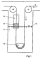
- Figure 1 schematically shows a cooling device for carrying out the method of the invention.
- FIG. 2 schematically represents a preferred embodiment of the device of FIG. 1.
- the cooling device for carrying out the process of the present invention is shown schematically in FIG. 1.
- This device comprises successively a “slow” cooling zone with boiling water 11, a transition zone 12 and a zone of cooling. "fast” cooling 13.
- the band S enters a tank of boiling water 11 in descending vertical strand.
- the direction of its stroke is modified by a return basket 15 whose height relative to the water level in the tank can be regulated in order to control the temperature of the strip at the outlet of the tank of boiling water 11.
- the Steel strip S comes out of the boiling water tank rising vertical strand, makes a passage through a transition section 12 and finally opens into a "fast" cooling box 13 always vertically rising strand.
- the "rapid" cooling is carried out in a stirred water tank, with a controlled water temperature and a water agitation rate.
- the "rapid" cooling is achieved by means of controlled temperature water projected onto the strip with a controlled flow rate.
- the "rapid" cooling is achieved by means of a “misting jet” consisting of a suspension of water droplets in a neutral gas, the temperature and the flow of water, as well as the flow of neutral gas being controlled.
- FIG. 2 A preferred embodiment for a device, called “sas” or “sealing device” in the following description, responsible for operating the transition between the cooling type “boiling water” and cooling “fast”, in order to implement the method of the present invention, is shown schematically in Figure 2.
- Said lock 12 comprises at least two stages of roller pairs 1,1 ', 2,2', 3,3 '.
- Each compartment of the sealing device 12 is delimited by two pairs of successive rollers, 1,1 'and 2,2', for example, and comprises means for the injection 7,7 ', 8,8' and the extraction 9.9 ', 10.10' of water ( Figure 2).
- Each compartment further comprises means for regulating parameters such as the pressure and the temperature of the water which fills or is in said compartment.
- the water pressure between two successive roller pairs is regulated to prevent water leakage from the "cooler" upper water tank.
- the pressure on the rollers of the same pair is sufficient to keep them in contact with the band.
- each compartment delimited by two pairs of rollers 1,1 ', 2,2', 3,3 'of the transition section 12 relative to the adjacent compartment (contiguous) of this same section, as the case may be, the boiling water tank or the rapid cooling box, is provided by means of 4.4 ', 5.5', 6.6 'flaps associated with said rollers, fixed to the frame of said section 12 and resting on the rollers respective 1,1 ', 2,2', 3,3 '.
- the chamber acts as a buffer to eliminate the influence of the eddies (waves of the order of one meter in height) created on the surface 14 of the boiling water tank by the water vapor generated during the contact between the boiling water and the hot band.
- eddies waves of the order of one meter in height
- these turbulence influence the operation of the "rapid" cooling system, resulting in inhomogeneous cooling of the steel strip, with the consequence of a possible degradation of the geometric properties of said band, essentially its flatness.
- a lock device with at least two pairs of rollers is essential for the control of leaks from the "fast" cooling box to the boiling water tank.
- a single pair of rollers if the strand is up, possible leaks down are likely to disturb the temperature of the water in the tank of boiling water and therefore to create an inhomogeneous cooling of the band before entering the "fast" cooling chamber 13 ( Figure 1), which causes problems of flatness of the band.
Landscapes
- Chemical & Material Sciences (AREA)
- Engineering & Computer Science (AREA)
- Physics & Mathematics (AREA)
- Thermal Sciences (AREA)
- Crystallography & Structural Chemistry (AREA)
- Mechanical Engineering (AREA)
- Materials Engineering (AREA)
- Metallurgy (AREA)
- Organic Chemistry (AREA)
- Heat Treatment Of Strip Materials And Filament Materials (AREA)
Claims (22)
- Verfahren zur Kühlung eines Stahlbandes im Durchlaufverfahren im Rahmen einer Glühbehandlung im Durchlaufverfahren, wobei das besagte Band wenigstens die folgenden Etappen durchläuft:- das Band durchläuft eine erste, sogenannte langsame Kühlung mit kochendem Wasser,- das Band durchläuft ein zweites sogenanntes schnelles Kühlverfahren bzw. Abschrecken mit Wasser,dadurch gekennzeichnet, dass das Band zwischen diesen beiden Kühlvorgängen durch eine Schleuse oder abgedichtete Vorrichtung läuft, die mindestens eine Kammer umfasst, und dass in der besagten Kammer die Temperatur (T, T') und der Druck (P, P') geregelt werden, um das Auslaufen flüssigen Wassers von der schnellen Kühlung in Richtung der langsamen Kühlung zu verhindern oder zu reduzieren; die Abfolge dieser drei Etappen erfolgt so, dass die Zeit zwischen zwei aufeinanderfolgenden Etappen so kurz wie möglich und vorzugsweise gleich Null ist.
- Verfahren nach Anspruch 1, dadurch gekennzeichnet, dass die Temperatur des Bandes beim Austritt aus der Kühlung mit kochendem Wasser geregelt wird, indem die Behandlungszeit des Bandes in der Kühlung mit kochendem Wasser geändert wird.
- Verfahren nach Anspruch 1 oder 2, dadurch gekennzeichnet, dass die Temperatur des Bandes beim Austritt aus der Kühlung mit kochendem Wasser mehr als 290°C beträgt.
- Verfahren nach einem der Ansprüche 1 bis 3, dadurch gekennzeichnet, dass der schnelle Kühlvorgang an einem senkrechten, nach oben laufenden Teil des Bandes durchgeführt wird, indem Wasser auf beide Seiten des Bandes gespritzt wird, vorzugsweise durch Düsen, wobei dieser Vorgang mit geregelter Wassermenge und -temperatur durchgeführt wird.
- Verfahren nach einem der Ansprüche 1 bis 3, dadurch gekennzeichnet, dass der schnelle Kühlvorgang an einem senkrechten, nach oben laufenden Teil des Bandes durchgeführt wird, indem Wassernebel auf beide Seiten des Bandes gespritzt wird, vorzugsweise mittels eines neutralen Trägergases; dieser Vorgang wird bei geregelten Bedingungen in Bezug auf die Wassermenge und temperatur, sowie die Neutralgasmenge durchgeführt.
- Verfahren nach einem der vorstehenden Ansprüche 1 bis 3, dadurch gekennzeichnet, dass der schnelle Kühlvorgang an einem senkrechten, nach oben laufenden Teil des Bandes durchgeführt wird, indem das Stahlband in einen Kasten geführt wird, der bewegtes Wasser enthält, wobei der Grad der Bewegung geregelt wird; dieser Vorgang wird bei geregelten Bedingungen in Bezug auf die Wassertemperatur in diesem Kasten durchgeführt; außerdem wird die Temperatur des Bandes beim Austritt aus dem besagten Kasten für die schnelle Kühlung geregelt, indem der Wasserstand in dem besagten Kasten geregelt wird.
- Verfahren nach einem der Ansprüche 4, 5 und 6, dadurch gekennzeichnet, dass die Temperatur des Stahlbandes beim Austritt aus der schnellen Kühlung geregelt wird, vorzugsweise mit Hilfe von Stellgliedern, die die Durchlaufgeschwindigkeit des Stahlbandes durch die schnelle Kühlung oder die Wassermenge und/oder die Wassertemperatur des für die Durchführung dieser schnellen Kühlung verwendeten Wassers ändern.
- Schleusenvorrichtung für die Anwendung des Durchlaufkühlverfahrens für ein Stahlband im Rahmen einer Durchlaufglühbehandlung gemäß einem der Ansprüche 1 bis 7, dadurch gekennzeichnet, dass die besagte Vorrichtung sich an einem senkrechten, nach oben laufenden Teil des Bandes unmittelbar nach einem Kühlbehälter mit kochendem Wasser befindet, der zur Durchführung der sogenannten langsamen Kühlung dieses Stahlbandes dient, und direkt vor einem Kühlkasten, der sich ebenfalls an diesem senkrechten, nach oben laufenden Teil des Bandes befindet und der Durchführung der sogenannten schnellen Kühlung dieses Stahlbandes dient, und dadurch, dass die besagte Vorrichtung wenigstens eine Kammer und Mittel zur Regelung der Temperatur (T, T') und des Drucks (P, P') in jeder Kammer umfasst.
- Vorrichtung gemäß Anspruch 8, dadurch gekennzeichnet, dass sie aus einem Behälter besteht, der mindestens zwei Stufen aufeinanderfolgender Rollenpaare (1, 1', 2, 2', 3, 3') umfasst.
- Vorrichtung gemäß Anspruch 9, dadurch gekennzeichnet, dass das untere Rollenpaar (3, 3') in den Behälter mit kochendem Wasser eintaucht.
- Vorrichtung gemäß Anspruch 9 oder 10, dadurch gekennzeichnet, dass zwei unmittelbar aufeinanderfolgende Rollenpaare eine sogenannte dichte Kammer in dem besagten Behälter begrenzen.
- Vorrichtung gemäß Anspruch 11, dadurch gekennzeichnet, dass die besagte Kammer gegenüber dem Behälter mit kochendem Wasser, gegenüber der oder den angrenzenden Kammer(n) oder auch gegenüber dem Kühlkasten für die schnelle Kühlung abgedichtet ist, wobei diese Abdichtung durch die zwei Rollenpaare, die die besagte Kammer begrenzen, und durch Abweiserbleche (4, 4', 5, 5', 6, 6') gewährleistet wird, die in Verbindung mit den besagten Rollen wirken, am Rahmen des Behälters befestigt sind und auf den jeweiligen Rollen (1, 1', 2, 2', 3, 3') aufliegen.
- Vorrichtung gemäß Anspruch 11 oder 12, dadurch gekennzeichnet, dass jede Kammer des Behälters mit Mitteln zum Einspritzen von Wasser (7, 7', 8, 8') in die besagte Kammer und zum Entziehen von Wasser (9, 9', 10, 10') aus der besagten Kammer ausgestattet ist.
- Vorrichtung gemäß Anspruch 13, dadurch gekennzeichnet, dass die Mittel zum Einspritzen von Wasser (7, 7', 8, 8') und zum Entziehen von Wasser (9, 9', 10, 10') bei jeder Kammer jeweils im unteren Bereich bzw. im oberen Bereich der jeweiligen Kammer angebracht sind.
- Vorrichtung gemäß Anspruch 13 oder 14, dadurch gekennzeichnet, dass jede Kammer über Mittel verfügt, die der Regelung der Wassereinspritz- und Wasserentzugsmenge in bzw. aus der besagten Kammer dienen.
- Vorrichtung nach einem der Ansprüche 13 bis 15, dadurch gekennzeichnet, dass jede Kammer über Mittel verfügt, um die Temperatur des in die besagte Kammer eingespritzten Wassers zu regeln.
- Vorrichtung nach einem der Ansprüche 13 bis 16, dadurch gekennzeichnet, dass jede Kammer über Mittel verfügt, um die Temperatur und den Druck des Wassers im Inneren der besagten Kammer zu regeln.
- Vorrichtung nach einem der Ansprüche 9 bis 17, dadurch gekennzeichnet, dass sie zwei Stufen Rollenpaare umfasst, die eine einzige Kammer im Schleusenbehälter begrenzen, wobei sich diese Kammer unmittelbar nach dem Behälter mit kochendem Wasser und unmittelbar vor dem Kasten für die schnelle Kühlung befindet.
- Regelungsverfahren für die Anwendung der Vorrichtung nach einem der Ansprüche 8 bis 18, dadurch gekennzeichnet, dass wenigstens der Druck (P') in der oberen Kammer geregelt wird, wobei sichergestellt wird, dass der besagte Druck (P') über den Rollen (1, 1'), die die Kammer nach oben begrenzen, jederzeit höher ist als der Druck, der nach den Rollen (1, 1') durch das Wasser ausgeübt wird, das sich im unteren Teil des Kühlkastens für die schnelle Kühlung angesammelt hat.
- Regelungsverfahren für die Anwendung der Vorrichtung nach Anspruch 18, wobei der Kasten für die schnelle Kühlung Wasser in geregelter Bewegung enthält, dadurch gekennzeichnet, dass der Druck in der Kammer der besagten Vorrichtung geregelt wird, so dass der besagte Druck höher ist als Ps + p.g.h, wobei Ps, p, g und h jeweils dem hydrostatischen Druck, der auf die freie Fläche (16) der im Kasten für die schnelle Kühlung aufrecht erhaltenen Wassersäule wirkt, der Volumenmasse des Wassers, der Beschleunigung der Schwerkraft und der Höhe der besagten Wassersäule entsprechen; diese Größen werden gemäß dem internationalen Einheitensystem ausgedrückt.
- Verfahren gemäß Anspruch 20, dadurch gekennzeichnet, dass in die Schleusenkammer Wasser eingespritzt wird, dessen Temperatur seiner Siedetemperatur entspricht.
- Verfahren gemäß Anspruch 21, dadurch gekennzeichnet, dass das Wasser, das in die Schleusenkammer eingespritzt wird, direkt dem Behälter mit kochendem Wasser entnommen wird, der sich direkt vor der besagten Schleuse befindet.
Applications Claiming Priority (2)
| Application Number | Priority Date | Filing Date | Title |
|---|---|---|---|
| BE200100653 | 2001-10-05 | ||
| BE2001/0653A BE1014418A3 (fr) | 2001-10-05 | 2001-10-05 | Procede et dispositif de refroidissement accelere en recuit continu. |
Publications (2)
| Publication Number | Publication Date |
|---|---|
| EP1300478A1 EP1300478A1 (de) | 2003-04-09 |
| EP1300478B1 true EP1300478B1 (de) | 2006-06-28 |
Family
ID=3897114
Family Applications (1)
| Application Number | Title | Priority Date | Filing Date |
|---|---|---|---|
| EP02447157A Expired - Lifetime EP1300478B1 (de) | 2001-10-05 | 2002-08-20 | Verfahren und Vorrichtung zum beschleunigten Abkühlen im Durchlaufglühverfahren |
Country Status (5)
| Country | Link |
|---|---|
| EP (1) | EP1300478B1 (de) |
| AT (1) | ATE331816T1 (de) |
| BE (1) | BE1014418A3 (de) |
| DE (1) | DE60212778T2 (de) |
| ES (1) | ES2267970T3 (de) |
Cited By (1)
| Publication number | Priority date | Publication date | Assignee | Title |
|---|---|---|---|---|
| WO2021024096A1 (en) | 2019-08-06 | 2021-02-11 | Arcelormittal | Device for cooling a steel strip |
Families Citing this family (6)
| Publication number | Priority date | Publication date | Assignee | Title |
|---|---|---|---|---|
| EP1538228A1 (de) * | 2003-12-01 | 2005-06-08 | R & D du groupe Cockerill-Sambre | Verfahren und Vorrichtung zum Kühlen einer Stahlband |
| WO2010049600A1 (fr) * | 2008-10-31 | 2010-05-06 | Siemens Vai Metals Technologies Sas | Four pour une installation de traitement thermique d'une bande d'acier en défilement continu et procédé associé |
| CN102534178B (zh) * | 2012-01-17 | 2013-06-05 | 江苏宝力重工科技有限公司 | 无取向硅钢带水封冷却装置 |
| CN104451117A (zh) * | 2014-09-23 | 2015-03-25 | 中冶赛迪工程技术股份有限公司 | 一种淬火板板形控制方法和装置 |
| JP6308287B2 (ja) * | 2015-12-28 | 2018-04-11 | Jfeスチール株式会社 | 急冷焼入れ装置及び急冷焼入れ方法 |
| CN113430360A (zh) * | 2021-06-07 | 2021-09-24 | 唐山钢铁集团高强汽车板有限公司 | 一种高强钢板退火过渡的控制方法 |
Family Cites Families (5)
| Publication number | Priority date | Publication date | Assignee | Title |
|---|---|---|---|---|
| GB1333116A (en) * | 1970-12-15 | 1973-10-10 | Nippon Kokan Kk | Continuous annealing plant for steel strip |
| BE887507A (fr) * | 1981-02-12 | 1981-06-01 | Centre Rech Metallurgique | Perfectionnements aux procedes de traitement thermique en continu de toles d'acier |
| BR9904910A (pt) * | 1998-03-26 | 2000-06-20 | Kawasaki Steel Co | Forno de tratamento térmico contìnuo e processo de controle da atmosfera e processo de resfriamento no forno |
| JP3514130B2 (ja) * | 1998-08-27 | 2004-03-31 | Jfeスチール株式会社 | 鋼帯の竪型冷却装置及び冷却方法 |
| BE1012215A3 (fr) * | 1998-10-01 | 2000-07-04 | Centre Rech Metallurgique | Procede de refroidissement en continu d'une tole en acier et dispositif pour sa mise en oeuvre. |
-
2001
- 2001-10-05 BE BE2001/0653A patent/BE1014418A3/fr not_active IP Right Cessation
-
2002
- 2002-08-20 AT AT02447157T patent/ATE331816T1/de not_active IP Right Cessation
- 2002-08-20 ES ES02447157T patent/ES2267970T3/es not_active Expired - Lifetime
- 2002-08-20 DE DE60212778T patent/DE60212778T2/de not_active Expired - Lifetime
- 2002-08-20 EP EP02447157A patent/EP1300478B1/de not_active Expired - Lifetime
Cited By (2)
| Publication number | Priority date | Publication date | Assignee | Title |
|---|---|---|---|---|
| WO2021024096A1 (en) | 2019-08-06 | 2021-02-11 | Arcelormittal | Device for cooling a steel strip |
| US12465966B2 (en) | 2019-08-06 | 2025-11-11 | Arcelormittal | Device for cooling a steel strip |
Also Published As
| Publication number | Publication date |
|---|---|
| DE60212778D1 (de) | 2006-08-10 |
| ATE331816T1 (de) | 2006-07-15 |
| EP1300478A1 (de) | 2003-04-09 |
| BE1014418A3 (fr) | 2003-10-07 |
| DE60212778T2 (de) | 2007-06-28 |
| ES2267970T3 (es) | 2007-03-16 |
Similar Documents
| Publication | Publication Date | Title |
|---|---|---|
| EP1300478B1 (de) | Verfahren und Vorrichtung zum beschleunigten Abkühlen im Durchlaufglühverfahren | |
| EP0909342B1 (de) | Verfahren zum kontinuierlichen beschichten eines sich bewegenden substrats mit einem metalldampf | |
| FR2793239A1 (fr) | Procede de fabrication de verre flotte, dispositif de mise en oeuvre et produits obtenus | |
| LU87997A1 (fr) | Procede de formation d'un revetement sur du verre | |
| EP1687455B1 (de) | Kühlprozess und -vorrichtung für eine stahlplatte | |
| LU84777A1 (fr) | Procede et dispositif de revetement de feuilles ou de rubans de matiere vitreuse | |
| CA2428485C (fr) | Procede et installation de revetement au trempe d'une bande metallique, notamment d'une bande d'acier | |
| EP0761829B1 (de) | Vorrichtung zum Kühlen von Walzgut | |
| EP1529122A2 (de) | Verfahren und vorrichtung zum patentieren von stahldrähten | |
| FR2492804A1 (fr) | Procede de production d'une feuille mince de verre par processus de flottage | |
| EP3686534B1 (de) | Verfahren und ofen für die wärmebehandlung eines hochwiderstandsfähigen stahlbandes, der eine temperatur-homogenisierungskammer umfasst | |
| CA2855927C (fr) | Procede de refroidissement de pieces metalliques ayant subi un traitement de nitruration / nitrocarburation en bain de sel fondu, l'installation pour la mise en oeuvre du procede et les pieces metalliques traitees | |
| EP4370719B1 (de) | Flüssigkeitskühlung eines laufenden bandes in einer kontinuierlichen anlage | |
| FR2833871A1 (fr) | Procede et installation de fabrication de bandes metalliques a partir de bandes coulees directement a partir de metal liquide | |
| FR2479795A1 (fr) | Procede d'amincissement de verre produit par flottage | |
| EP1404882B1 (de) | Verfahren zum abschrecken von stahl mittels druckluft | |
| CH269520A (fr) | Procédé pour le revêtement d'objets en métal par des couches d'un métal différent. | |
| FR2510542A1 (fr) | Procede de production de verre a vitres mince par processus de flottaison de haute qualite | |
| EP0992593B1 (de) | Vorrichtung und Verfahren zum kontinuierlichen Abkühlen von Stahlblechen | |
| BE888644A (fr) | Appareil et procede pour supporter un feuillard metallique sous une pression de gaz statique, | |
| BE449144A (fr) | Perfectionnements aux procédés et dispositifs pour le revêtement d'objets en métal par des couches protectrices d'un métal différent | |
| FR2919816A1 (fr) | Installation de revetement d'une bande metallique | |
| FR2570690A1 (fr) | Procede et dispositif pour l'extraction d'un ruban de verre a la sortie d'un four de flottage et verre plat obtenu | |
| WO2001091948A1 (fr) | Procede et dispositif pour proteger un metal fondu non ferreux | |
| FR3095452A1 (fr) | Ligne de traitement en continu de bandes métalliques à double usage |
Legal Events
| Date | Code | Title | Description |
|---|---|---|---|
| PUAI | Public reference made under article 153(3) epc to a published international application that has entered the european phase |
Free format text: ORIGINAL CODE: 0009012 |
|
| AK | Designated contracting states |
Kind code of ref document: A1 Designated state(s): AT BE BG CH CY CZ DE DK EE ES FI FR GB GR IE IT LI LU MC NL PT SE SK TR Designated state(s): AT BE BG CH CY CZ DE DK EE ES FI FR GB GR IE IT LI LU MC NL PT SE SK TR |
|
| AX | Request for extension of the european patent |
Extension state: AL LT LV MK RO SI |
|
| 17P | Request for examination filed |
Effective date: 20030709 |
|
| AKX | Designation fees paid |
Designated state(s): AT BE BG CH CY CZ DE DK EE ES FI FR GB GR IE IT LI LU MC NL PT SE SK TR |
|
| RAP1 | Party data changed (applicant data changed or rights of an application transferred) |
Owner name: RECHERCHE ET DEVELOPPEMENT GROUPE COCKERILL SAMBRE Owner name: CENTRE DE RECHERCHES METALLURGIQUES - CENTRUM VOOR |
|
| 17Q | First examination report despatched |
Effective date: 20050608 |
|
| GRAP | Despatch of communication of intention to grant a patent |
Free format text: ORIGINAL CODE: EPIDOSNIGR1 |
|
| GRAS | Grant fee paid |
Free format text: ORIGINAL CODE: EPIDOSNIGR3 |
|
| GRAA | (expected) grant |
Free format text: ORIGINAL CODE: 0009210 |
|
| AK | Designated contracting states |
Kind code of ref document: B1 Designated state(s): AT BE BG CH CY CZ DE DK EE ES FI FR GB GR IE IT LI LU MC NL PT SE SK TR |
|
| PG25 | Lapsed in a contracting state [announced via postgrant information from national office to epo] |
Ref country code: FI Free format text: LAPSE BECAUSE OF FAILURE TO SUBMIT A TRANSLATION OF THE DESCRIPTION OR TO PAY THE FEE WITHIN THE PRESCRIBED TIME-LIMIT Effective date: 20060628 Ref country code: SK Free format text: LAPSE BECAUSE OF FAILURE TO SUBMIT A TRANSLATION OF THE DESCRIPTION OR TO PAY THE FEE WITHIN THE PRESCRIBED TIME-LIMIT Effective date: 20060628 Ref country code: AT Free format text: LAPSE BECAUSE OF FAILURE TO SUBMIT A TRANSLATION OF THE DESCRIPTION OR TO PAY THE FEE WITHIN THE PRESCRIBED TIME-LIMIT Effective date: 20060628 Ref country code: IE Free format text: LAPSE BECAUSE OF FAILURE TO SUBMIT A TRANSLATION OF THE DESCRIPTION OR TO PAY THE FEE WITHIN THE PRESCRIBED TIME-LIMIT Effective date: 20060628 Ref country code: CZ Free format text: LAPSE BECAUSE OF FAILURE TO SUBMIT A TRANSLATION OF THE DESCRIPTION OR TO PAY THE FEE WITHIN THE PRESCRIBED TIME-LIMIT Effective date: 20060628 |
|
| REG | Reference to a national code |
Ref country code: GB Ref legal event code: FG4D Free format text: NOT ENGLISH |
|
| REG | Reference to a national code |
Ref country code: CH Ref legal event code: EP |
|
| REG | Reference to a national code |
Ref country code: IE Ref legal event code: FG4D Free format text: LANGUAGE OF EP DOCUMENT: FRENCH |
|
| REF | Corresponds to: |
Ref document number: 60212778 Country of ref document: DE Date of ref document: 20060810 Kind code of ref document: P |
|
| PG25 | Lapsed in a contracting state [announced via postgrant information from national office to epo] |
Ref country code: MC Free format text: LAPSE BECAUSE OF NON-PAYMENT OF DUE FEES Effective date: 20060831 Ref country code: CH Free format text: LAPSE BECAUSE OF NON-PAYMENT OF DUE FEES Effective date: 20060831 Ref country code: LI Free format text: LAPSE BECAUSE OF NON-PAYMENT OF DUE FEES Effective date: 20060831 |
|
| PG25 | Lapsed in a contracting state [announced via postgrant information from national office to epo] |
Ref country code: DK Free format text: LAPSE BECAUSE OF FAILURE TO SUBMIT A TRANSLATION OF THE DESCRIPTION OR TO PAY THE FEE WITHIN THE PRESCRIBED TIME-LIMIT Effective date: 20060928 Ref country code: SE Free format text: LAPSE BECAUSE OF FAILURE TO SUBMIT A TRANSLATION OF THE DESCRIPTION OR TO PAY THE FEE WITHIN THE PRESCRIBED TIME-LIMIT Effective date: 20060928 |
|
| GBT | Gb: translation of ep patent filed (gb section 77(6)(a)/1977) |
Effective date: 20060908 |
|
| PG25 | Lapsed in a contracting state [announced via postgrant information from national office to epo] |
Ref country code: PT Free format text: LAPSE BECAUSE OF FAILURE TO SUBMIT A TRANSLATION OF THE DESCRIPTION OR TO PAY THE FEE WITHIN THE PRESCRIBED TIME-LIMIT Effective date: 20061128 |
|
| REG | Reference to a national code |
Ref country code: IE Ref legal event code: FD4D |
|
| REG | Reference to a national code |
Ref country code: ES Ref legal event code: FG2A Ref document number: 2267970 Country of ref document: ES Kind code of ref document: T3 |
|
| REG | Reference to a national code |
Ref country code: CH Ref legal event code: PL |
|
| PLBE | No opposition filed within time limit |
Free format text: ORIGINAL CODE: 0009261 |
|
| STAA | Information on the status of an ep patent application or granted ep patent |
Free format text: STATUS: NO OPPOSITION FILED WITHIN TIME LIMIT |
|
| 26N | No opposition filed |
Effective date: 20070329 |
|
| PG25 | Lapsed in a contracting state [announced via postgrant information from national office to epo] |
Ref country code: GR Free format text: LAPSE BECAUSE OF FAILURE TO SUBMIT A TRANSLATION OF THE DESCRIPTION OR TO PAY THE FEE WITHIN THE PRESCRIBED TIME-LIMIT Effective date: 20060929 |
|
| PG25 | Lapsed in a contracting state [announced via postgrant information from national office to epo] |
Ref country code: BG Free format text: LAPSE BECAUSE OF FAILURE TO SUBMIT A TRANSLATION OF THE DESCRIPTION OR TO PAY THE FEE WITHIN THE PRESCRIBED TIME-LIMIT Effective date: 20060928 Ref country code: EE Free format text: LAPSE BECAUSE OF FAILURE TO SUBMIT A TRANSLATION OF THE DESCRIPTION OR TO PAY THE FEE WITHIN THE PRESCRIBED TIME-LIMIT Effective date: 20060628 |
|
| PG25 | Lapsed in a contracting state [announced via postgrant information from national office to epo] |
Ref country code: TR Free format text: LAPSE BECAUSE OF FAILURE TO SUBMIT A TRANSLATION OF THE DESCRIPTION OR TO PAY THE FEE WITHIN THE PRESCRIBED TIME-LIMIT Effective date: 20060628 |
|
| PG25 | Lapsed in a contracting state [announced via postgrant information from national office to epo] |
Ref country code: CY Free format text: LAPSE BECAUSE OF FAILURE TO SUBMIT A TRANSLATION OF THE DESCRIPTION OR TO PAY THE FEE WITHIN THE PRESCRIBED TIME-LIMIT Effective date: 20060628 |
|
| PGFP | Annual fee paid to national office [announced via postgrant information from national office to epo] |
Ref country code: LU Payment date: 20140723 Year of fee payment: 13 |
|
| PGFP | Annual fee paid to national office [announced via postgrant information from national office to epo] |
Ref country code: NL Payment date: 20140721 Year of fee payment: 13 |
|
| PGFP | Annual fee paid to national office [announced via postgrant information from national office to epo] |
Ref country code: FR Payment date: 20140822 Year of fee payment: 13 Ref country code: GB Payment date: 20140725 Year of fee payment: 13 |
|
| PG25 | Lapsed in a contracting state [announced via postgrant information from national office to epo] |
Ref country code: LU Free format text: LAPSE BECAUSE OF NON-PAYMENT OF DUE FEES Effective date: 20150820 |
|
| GBPC | Gb: european patent ceased through non-payment of renewal fee |
Effective date: 20150820 |
|
| REG | Reference to a national code |
Ref country code: NL Ref legal event code: MM Effective date: 20150901 |
|
| REG | Reference to a national code |
Ref country code: FR Ref legal event code: ST Effective date: 20160429 |
|
| PG25 | Lapsed in a contracting state [announced via postgrant information from national office to epo] |
Ref country code: NL Free format text: LAPSE BECAUSE OF NON-PAYMENT OF DUE FEES Effective date: 20150901 |
|
| PG25 | Lapsed in a contracting state [announced via postgrant information from national office to epo] |
Ref country code: GB Free format text: LAPSE BECAUSE OF NON-PAYMENT OF DUE FEES Effective date: 20150820 |
|
| PG25 | Lapsed in a contracting state [announced via postgrant information from national office to epo] |
Ref country code: FR Free format text: LAPSE BECAUSE OF NON-PAYMENT OF DUE FEES Effective date: 20150831 |
|
| PGFP | Annual fee paid to national office [announced via postgrant information from national office to epo] |
Ref country code: DE Payment date: 20200721 Year of fee payment: 19 Ref country code: ES Payment date: 20200901 Year of fee payment: 19 |
|
| PGFP | Annual fee paid to national office [announced via postgrant information from national office to epo] |
Ref country code: BE Payment date: 20200724 Year of fee payment: 19 Ref country code: IT Payment date: 20200721 Year of fee payment: 19 |
|
| REG | Reference to a national code |
Ref country code: DE Ref legal event code: R119 Ref document number: 60212778 Country of ref document: DE |
|
| REG | Reference to a national code |
Ref country code: BE Ref legal event code: MM Effective date: 20210831 |
|
| PG25 | Lapsed in a contracting state [announced via postgrant information from national office to epo] |
Ref country code: IT Free format text: LAPSE BECAUSE OF NON-PAYMENT OF DUE FEES Effective date: 20210820 Ref country code: DE Free format text: LAPSE BECAUSE OF NON-PAYMENT OF DUE FEES Effective date: 20220301 Ref country code: BE Free format text: LAPSE BECAUSE OF NON-PAYMENT OF DUE FEES Effective date: 20210831 |
|
| REG | Reference to a national code |
Ref country code: ES Ref legal event code: FD2A Effective date: 20220929 |
|
| PG25 | Lapsed in a contracting state [announced via postgrant information from national office to epo] |
Ref country code: ES Free format text: LAPSE BECAUSE OF NON-PAYMENT OF DUE FEES Effective date: 20210821 |