EP1300546A1 - Ancrage de forage et d'injection - Google Patents
Ancrage de forage et d'injection Download PDFInfo
- Publication number
- EP1300546A1 EP1300546A1 EP02021000A EP02021000A EP1300546A1 EP 1300546 A1 EP1300546 A1 EP 1300546A1 EP 02021000 A EP02021000 A EP 02021000A EP 02021000 A EP02021000 A EP 02021000A EP 1300546 A1 EP1300546 A1 EP 1300546A1
- Authority
- EP
- European Patent Office
- Prior art keywords
- injection
- drill
- anchor according
- steel tube
- sleeve
- Prior art date
- Legal status (The legal status is an assumption and is not a legal conclusion. Google has not performed a legal analysis and makes no representation as to the accuracy of the status listed.)
- Granted
Links
- 238000002347 injection Methods 0.000 title claims abstract description 105
- 239000007924 injection Substances 0.000 title claims abstract description 105
- 238000005553 drilling Methods 0.000 title claims description 12
- 229910000831 Steel Inorganic materials 0.000 claims abstract description 48
- 239000010959 steel Substances 0.000 claims abstract description 48
- 238000011010 flushing procedure Methods 0.000 claims abstract description 12
- 230000008878 coupling Effects 0.000 claims description 26
- 238000010168 coupling process Methods 0.000 claims description 26
- 238000005859 coupling reaction Methods 0.000 claims description 26
- 239000012530 fluid Substances 0.000 claims description 11
- 230000006835 compression Effects 0.000 claims description 10
- 238000007906 compression Methods 0.000 claims description 10
- 230000007704 transition Effects 0.000 claims description 4
- 230000000903 blocking effect Effects 0.000 claims 1
- 238000007789 sealing Methods 0.000 description 8
- 238000003825 pressing Methods 0.000 description 6
- 238000004519 manufacturing process Methods 0.000 description 4
- 238000005520 cutting process Methods 0.000 description 3
- 238000000034 method Methods 0.000 description 3
- 239000011435 rock Substances 0.000 description 3
- 238000004873 anchoring Methods 0.000 description 2
- 238000003780 insertion Methods 0.000 description 2
- 230000037431 insertion Effects 0.000 description 2
- 230000002093 peripheral effect Effects 0.000 description 2
- XLYOFNOQVPJJNP-UHFFFAOYSA-N water Substances O XLYOFNOQVPJJNP-UHFFFAOYSA-N 0.000 description 2
- 230000015572 biosynthetic process Effects 0.000 description 1
- 230000001419 dependent effect Effects 0.000 description 1
- 239000007788 liquid Substances 0.000 description 1
- 239000000463 material Substances 0.000 description 1
- 238000005065 mining Methods 0.000 description 1
- 238000005728 strengthening Methods 0.000 description 1
Images



Classifications
-
- E—FIXED CONSTRUCTIONS
- E21—EARTH OR ROCK DRILLING; MINING
- E21D—SHAFTS; TUNNELS; GALLERIES; LARGE UNDERGROUND CHAMBERS
- E21D21/00—Anchoring-bolts for roof, floor in galleries or longwall working, or shaft-lining protection
- E21D21/0026—Anchoring-bolts for roof, floor in galleries or longwall working, or shaft-lining protection characterised by constructional features of the bolts
-
- E—FIXED CONSTRUCTIONS
- E21—EARTH OR ROCK DRILLING; MINING
- E21D—SHAFTS; TUNNELS; GALLERIES; LARGE UNDERGROUND CHAMBERS
- E21D20/00—Setting anchoring-bolts
- E21D20/02—Setting anchoring-bolts with provisions for grouting
- E21D20/028—Devices or accesories for injecting a grouting liquid in a bore-hole
-
- E—FIXED CONSTRUCTIONS
- E21—EARTH OR ROCK DRILLING; MINING
- E21D—SHAFTS; TUNNELS; GALLERIES; LARGE UNDERGROUND CHAMBERS
- E21D21/00—Anchoring-bolts for roof, floor in galleries or longwall working, or shaft-lining protection
- E21D21/0026—Anchoring-bolts for roof, floor in galleries or longwall working, or shaft-lining protection characterised by constructional features of the bolts
- E21D21/0073—Anchoring-bolts having an inflatable sleeve, e.g. hollow sleeve expanded by a fluid
Definitions
- the invention relates to an injection drill anchor made of at least one steel tube.
- Injection drill anchors are used in a wide variety of designs Connecting used rock layers used in particular in underground mining, but also routes and tunnels Keep cavities open.
- WO 91/15657 discloses an injection drill anchor with an anchor tube, a drill bit at the anchor tip facing the deepest hole and Has flushing and injection openings.
- the anchor tube is with a borehole closure and at the end protruding from the borehole with a detachable connection element.
- the as Section formed drill with a trained as a drilling adapter Connection element is provided against a section designed as an anchor tube interchangeable, the section with a borehole closure and a check valve is provided.
- each injection valve to be individually charged with the pressing medium so that the Pressing process in accordance with the local conditions of the borehole wall adapted manner can be carried out.
- Which are the injection valves forming radial expansion of the anchoring body can be made more reproducible in this way.
- DE 44 45 626 A1 makes the proposal to include an injection sliding drill anchor an inflatable packer, an inflatable jacket and a stable support tube equip and integrate a valve in the support tube. Via the inflation valve the inflatable packer is fixed, this process only being initiated when the drilling is finished. For this, at the beginning of the Injection process, a valve body is flushed into the inflatable packer, which attaches itself supports a valve seat provided and trained there. The The valve body is replaced by pressure increase after the expansion work destroyed, so that then injection material in the force application area can penetrate.
- the inflatable packer is equipped with a post-injection valve, which enables re-pressing of the free spin track.
- the object of the invention is based on the prior art based on creating an injection drill anchor, which even with one less stable mountains securely and positionally fixed in a borehole can be.
- the invention solves this problem by the specified in claim 1 Characteristics.
- the core of the invention is the design of an injection drill anchor, which both to create a borehole, to seal the borehole, to insert of an injection medium in the mountains and as a load-bearing element of mountain protection serves.
- the injection drill anchor comprises at least a steel tube that has a smooth cylindrical surface middle longitudinal section and at the ends of outer threaded sections.
- these threaded sections there is a first threaded section on the one hand with a drill drive and on the other hand in exchange with the drill drive can be coupled with an injection adapter for supplying an injection medium.
- the second threaded section at the other end of the steel pipe is used for the coupling with an outlet bore for a drill bit the rod head containing the injection medium.
- On the one with at least A central hose section provided with a transverse bore is an inflation hose fixed in position.
- the steel pipe can be coupled as required.
- the first threaded section is used to insert an injection drill anchor coupled with a drill drive.
- a drill drive Through the drill drive is a Borehole made, at the same time a flushing fluid supplied via the drill drive can be. However, the pressure of the flushing fluid must not be so great that the inflation hose is activated.
- the injection medium is inserted into the steel pipe via the injection adapter introduced, the locking ball to the mouth of the locking hole in Rod head is shifted in the longitudinal channel.
- the locking ball seals the Exit area of the longitudinal channel into the rod head.
- the injection medium thereby occurs through the cross hole in the wall of the steel pipe Inflation hose.
- This inflates and seals depending on pressure and form-fitting against the wall of the borehole.
- the pressure of the injection medium so far increased that the locking ball is deformed by the Locking hole is pressed in the rod head, thereby in the interior in the Rod head arrives and thus the path for the injection medium via the Rod head and the outlet holes provided there in the surrounding mountains are released.
- Due to the pressure-dependent sealing of the inflation hose in the Borehole can inject the injection medium into the rock at high pressure become. This makes the injection area in the surrounding mountains essential increased. This option allows the number of to be set Anchors can be significantly reduced.
- the injection adapter is removed from the first thread section removed and used for further injections.
- the invention makes drillable injection drill anchors with injection packers possible consequently, with simple means in a comparatively short time a mountain anchor - even in an unused mountain range - with optimal injection of injection liquids perform.
- the rod head with an internal thread Threaded sleeve screwed onto the second threaded section.
- the drill bit is according to claim 3 with an internal thread provided screw sleeve on a connector with an external thread of the rod head. Between the threaded sleeve and the socket of the rod head, the exit bores extending from the interior extend for the injection medium. These are based on the interior preferably arranged slightly inclined towards the steel tube.
- the drill bit with a Longitudinal channel provided.
- the injection medium can also pass through this step into the borehole when the locking ball passes over the longitudinal channel has been pressed into the drill hole in the drill bit. Is accordingly the diameter in the longitudinal channel of the drill bit in relation to the diameter the locking ball designed.
- the drilling cuttings that occur during the production of the borehole are perfect circumferential side of the steel pipe can be discharged according to the Feature of claim 5 on the end facing the drill bit of the inflation hose fixed at the end with press sleeves on the steel tube one towards the drill bit down to the outer surface of the steel pipe tapered deflector sleeve attached. A jam in the transport of the Drilling cuttings are avoided.
- the wall thickness of the deflector sleeve corresponds preferably the wall thickness of the compression sleeves.
- the openings of the cross holes in the outer surface of the steel tube are according to claim 7 by a tightly enclosing the steel tube elastic sleeve covered.
- the elasticity of the sleeve is designed so that it only yields at a certain internal pressure in the longitudinal channel of the steel pipe and the injection medium into the inflation hose for pressing the borehole wall releases.
- the sleeve can for example consist of a Hose section to be formed.
- the drill drive shows - at least indirectly - according to the characteristics of claim 9 a rotating union for a flushing fluid, such as Water, and a pipe coupling connected to the rotating union.
- the Pipe coupling comprises two limited in an annular coupling jacket rotatable and radially displaceable against an elastic restoring force Clamping jaws with inner thread segments adapted to the first thread section and locking balls mounted in circumferential recesses.
- Clamping jaws with inner thread segments adapted to the first thread section and locking balls mounted in circumferential recesses.
- In the cylindrical inner surface of the clutch jacket are diametrically opposed to each other opposite locking recesses in a circumferential direction intended. The areas of these recesses extend from one radial shoulder first in the circumferential direction and then slightly increasing until they pass into the inner surface.
- the locking balls are caused by the curve of the recesses pressed radially inwards so that they can then on the Roll along the inner surface of the coupling jacket.
- the Clamping jaws with the inner thread segments make up the first thread section and if the drilling drive continues to activate, turn it Steel pipe with the drill bit at the end.
- the drill drive is stopped and turned the pipe coupling back 90 ° until the locking balls under the influence of the elastic restoring force in the recesses arrive and the thread segments detach from the first thread section.
- the drill drive is no longer connected to the injection drill anchor. Then the rotary union with the pipe coupling from the first thread section are removed.
- a particularly advantageous embodiment of the invention is according to claim 10 seen in that the elastic restoring force for between segment-like, supported on the inner surface of the coupling jacket Sliding bodies radially positively guided jaws by next to the Threaded segments arranged helical compression springs is formed.
- the ends the helical compression springs are preferably in the pockets of the clamping jaws.
- the Hose connection is used to connect to an injection line.
- a quick snap lock is provided.
- the mixer serves the production of a correct consistency of the injection medium, while the check valve reflows the injection medium Filling the gap between the borehole wall and the injection drill anchor prevented.
- FIGS. 1 and 2 is an injection drill anchor for strengthening a used mountain range.
- the injection drill anchor 1 includes (see also FIG. 3) a steel pipe 2 a longitudinal channel 3.
- the ends of the steel tube 2 have outer threaded sections 4, 5 on.
- a smooth extends between the threaded sections 4, 5 cylindrical middle section 6.
- In this section 6 there are four offset from each other by 90 ° on the circumference and in pairs in diametrical Arrangement in two parallel transverse planes Q1, Q2 provided cross holes 7 arranged in the wall 8 of the steel tube 2.
- the mouths of the Cross bores 7 in the outer surface 9 of the steel tube 2 are through a the steel tube 2 tightly enclosing elastic sleeve 10, e.g. in form of Hose section, covered.
- the axial position of the elastic sleeve 10 the steel tube 2 is through two ends of the sleeve 10 on the steel tube 2nd fixed fixing rings 11 secured.
- the cross bores 7, the sleeve 10 and the fixing rings 11 are one Inflatable hose 12 covered.
- the inflation hose 12 is in the vicinity of its end faces 13 fixed in position on the steel tube 2 by pressing sleeves 14.
- the drill bit 15 has a screw sleeve 17 an internal thread 18 with which it fits onto an external thread 19 having nozzle 20 of a rod head 21 is set, which in turn with a threaded sleeve 23 having an internal thread 22 on the second Threaded section 5 of the steel tube 2 is screwed.
- the drill bit 15 is with provided a central longitudinal channel 24.
- the rod head 21 extends from the bottom 25 of the threaded sleeve 23 a locking bore 26 with a sealing seat 27, which the longitudinal channel 3 in Steel tube 2 is facing.
- the locking bore 26 opens out via a conical Length section 28 in an interior space 29 which is larger in diameter than that Locking hole 26 and also larger than the longitudinal channel 24 in the drill bit 15 is measured.
- a plurality of outlet bores 30 extend from the interior 29 , which open into the peripheral surface 31 of the rod head 21. The exit bores 30 are inclined away from the drill bit 15.
- the injection drill anchor 1 described above is used to manufacture a Borehole in the mountains with a rotary feedthrough 32 as part of a not Drill drive BA illustrated in more detail and with one with the rotating union 32 connected pipe coupling 33 connected ( Figures 1 and 5 to 7).
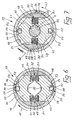
- the rotating union 32 comprises an annular housing 34 with a connection 35 for a flushing fluid SF, e.g. Water (Figure 5). From one with that Connection 35 connected ring channel 41 in the housing 34 cross holes 36 to a central blind bore 37 in the with the drill drive BA detachable rotor 38 of the rotary union 32. The areas next to the mouths of the cross bores 36 in the outer surface 39 of the rotor 38 sealed by sealing rings 40 chambered in the housing 34. The axial Relative position of the housing 34 and the rotor 38 is by a radial flange 42 guaranteed on the rotor 38 and by a locking ring 43.
- a flushing fluid SF e.g. Water
- the clamping jaws 47 are adapted to the first threaded section 4 Thread segments 50 on. Between the thread segments 50 and there are pocket-like recesses 51 in the sliding bodies 49 (FIG. 6) the helical compression springs 52 are inserted. The helical compression springs 52 try to move the jaws 47 radially outwards.
- recesses 56 are incorporated in a diametrical offset.
- the Locking recesses 56 extend from a radial shoulder 57 a peripheral surface 58 and an adjoining inclined surface Transition surface 59 into the inner surface 48 of the coupling jacket 44th
- a flexible locking ball 64 with a defined hardness in the Longitudinal channel 3 of the steel tube 2 introduced ( Figure 2).
- the diameter of the Locking ball 64 is smaller than the diameter of the longitudinal channel 3, however larger than the diameter of the locking bore 26 in the rod head 21.
- the injection adapter 65 also has a screw sleeve in the longitudinal direction 66 welded pipe section 69 a hose connection 70, a Mixer 71 and a check valve 72.
- the injection medium IM can therefore not through the rod head 21 in the Emerge from the borehole. Rather, the injection medium IM is under pressure via the transverse bores 7 with expansion of the elastic sleeve 10 (FIG 4) enter the inflation hose 12 and its middle, between the Press the compression sleeve 14 located area 73 against the borehole wall. The injection pressure then deforms by further increasing the injection pressure Lock ball 64 to an oval locking body (dash-dotted lines in Figure 9) and enters through the locking bore 26 into the interior 29 of the rod head 21 a. The injection medium IM can now come from the interior 29 step into the borehole via the outlet bores 30. A transition too Via the longitudinal channel 24 in the drill bit 15 is optionally possible.
- the injection medium IM is stopped. After curing the Injection medium IM can the injection adapter 65 after removal of the injection line from the hose connection 70 from the first threaded section 4 be turned off.
Landscapes
- Engineering & Computer Science (AREA)
- Mining & Mineral Resources (AREA)
- Structural Engineering (AREA)
- Life Sciences & Earth Sciences (AREA)
- General Life Sciences & Earth Sciences (AREA)
- Geochemistry & Mineralogy (AREA)
- Geology (AREA)
- Earth Drilling (AREA)
- Devices For Conveying Motion By Means Of Endless Flexible Members (AREA)
- Sewing Machines And Sewing (AREA)
- Saccharide Compounds (AREA)
- Nozzles (AREA)
Applications Claiming Priority (2)
| Application Number | Priority Date | Filing Date | Title |
|---|---|---|---|
| DE10148683A DE10148683C1 (de) | 2001-10-02 | 2001-10-02 | Injektionsbohrsanker |
| DE10148683 | 2001-10-02 |
Publications (2)
| Publication Number | Publication Date |
|---|---|
| EP1300546A1 true EP1300546A1 (fr) | 2003-04-09 |
| EP1300546B1 EP1300546B1 (fr) | 2006-10-25 |
Family
ID=7701184
Family Applications (1)
| Application Number | Title | Priority Date | Filing Date |
|---|---|---|---|
| EP02021000A Expired - Lifetime EP1300546B1 (fr) | 2001-10-02 | 2002-09-20 | Ancrage de forage et d'injection |
Country Status (3)
| Country | Link |
|---|---|
| EP (1) | EP1300546B1 (fr) |
| AT (1) | ATE343708T1 (fr) |
| DE (2) | DE10148683C1 (fr) |
Cited By (4)
| Publication number | Priority date | Publication date | Assignee | Title |
|---|---|---|---|---|
| CN110593927A (zh) * | 2019-09-30 | 2019-12-20 | 宁夏久威矿山安全工程有限责任公司 | 一种深浅可调式注浆结构及注浆方法 |
| CN115929369A (zh) * | 2022-12-06 | 2023-04-07 | 中煤科工开采研究院有限公司 | 锚杆支护用的多功能钻箱 |
| CN118601212A (zh) * | 2024-05-31 | 2024-09-06 | 龙督实业集团有限公司 | 一种防止安装松动的可调式铝方通的固定结构 |
| CN119221972A (zh) * | 2024-12-05 | 2024-12-31 | 山东省煤田地质规划勘察研究院 | 一种煤矿巷道冲击地压防治装置 |
Families Citing this family (4)
| Publication number | Priority date | Publication date | Assignee | Title |
|---|---|---|---|---|
| DE10336040B4 (de) * | 2003-08-01 | 2006-12-28 | Hilti Ag | Adapter für einen selbstbohrenden Gebirgsanker |
| AU2006317519B2 (en) * | 2005-11-24 | 2012-11-29 | Peter Andrew Gray | Self drilling rock bolt |
| DE102008005452B4 (de) * | 2008-01-21 | 2009-12-31 | Dmi Injektionstechnik Gmbh | Verfahren zum Verfestigen von Bodenabschnitten und Vorrichtung zur Durchführung des Verfahrens |
| DE102012201662A1 (de) | 2012-02-06 | 2013-08-08 | Hilti Aktiengesellschaft | Setzwerkzeug und Verfahren zur Montage einer Ankerstange |
Citations (6)
| Publication number | Priority date | Publication date | Assignee | Title |
|---|---|---|---|---|
| DE936082C (de) | 1954-01-02 | 1956-07-12 | Wilhelm Weghuber | Verfahren zum Verbinden von Gesteinsschichten im Bergbau und Mittel zur Ausuebung des Verfahrens |
| DE3145923A1 (de) | 1981-11-20 | 1983-06-01 | Dyckerhoff & Widmann AG, 8000 München | Verankerung fuer ein ankerzugglied, insbesondere fuer einen felsanker |
| DE3400182C2 (fr) | 1984-01-04 | 1989-07-06 | Friedr. Ischebeck Gmbh, 5828 Ennepetal, De | |
| WO1991015657A1 (fr) | 1990-04-11 | 1991-10-17 | Bergwerksverband Gmbh | Systeme d'ancrage pour puits d'injection |
| DE4445626A1 (de) | 1994-12-21 | 1996-06-27 | Willich F Berg Bautechnik | Injektionsgleitbohranker |
| DE19702749A1 (de) | 1997-01-27 | 1998-07-30 | Reburg Patentverwertungs Gmbh | Verfahren zum Setzen eines Injektionsbohrankers und Vorrichtung zur Durchführung dieses Verfahrens |
-
2001
- 2001-10-02 DE DE10148683A patent/DE10148683C1/de not_active Expired - Fee Related
-
2002
- 2002-09-20 EP EP02021000A patent/EP1300546B1/fr not_active Expired - Lifetime
- 2002-09-20 AT AT02021000T patent/ATE343708T1/de not_active IP Right Cessation
- 2002-09-20 DE DE50208530T patent/DE50208530D1/de not_active Expired - Fee Related
Patent Citations (6)
| Publication number | Priority date | Publication date | Assignee | Title |
|---|---|---|---|---|
| DE936082C (de) | 1954-01-02 | 1956-07-12 | Wilhelm Weghuber | Verfahren zum Verbinden von Gesteinsschichten im Bergbau und Mittel zur Ausuebung des Verfahrens |
| DE3145923A1 (de) | 1981-11-20 | 1983-06-01 | Dyckerhoff & Widmann AG, 8000 München | Verankerung fuer ein ankerzugglied, insbesondere fuer einen felsanker |
| DE3400182C2 (fr) | 1984-01-04 | 1989-07-06 | Friedr. Ischebeck Gmbh, 5828 Ennepetal, De | |
| WO1991015657A1 (fr) | 1990-04-11 | 1991-10-17 | Bergwerksverband Gmbh | Systeme d'ancrage pour puits d'injection |
| DE4445626A1 (de) | 1994-12-21 | 1996-06-27 | Willich F Berg Bautechnik | Injektionsgleitbohranker |
| DE19702749A1 (de) | 1997-01-27 | 1998-07-30 | Reburg Patentverwertungs Gmbh | Verfahren zum Setzen eines Injektionsbohrankers und Vorrichtung zur Durchführung dieses Verfahrens |
Cited By (4)
| Publication number | Priority date | Publication date | Assignee | Title |
|---|---|---|---|---|
| CN110593927A (zh) * | 2019-09-30 | 2019-12-20 | 宁夏久威矿山安全工程有限责任公司 | 一种深浅可调式注浆结构及注浆方法 |
| CN115929369A (zh) * | 2022-12-06 | 2023-04-07 | 中煤科工开采研究院有限公司 | 锚杆支护用的多功能钻箱 |
| CN118601212A (zh) * | 2024-05-31 | 2024-09-06 | 龙督实业集团有限公司 | 一种防止安装松动的可调式铝方通的固定结构 |
| CN119221972A (zh) * | 2024-12-05 | 2024-12-31 | 山东省煤田地质规划勘察研究院 | 一种煤矿巷道冲击地压防治装置 |
Also Published As
| Publication number | Publication date |
|---|---|
| DE10148683C1 (de) | 2002-10-24 |
| ATE343708T1 (de) | 2006-11-15 |
| EP1300546B1 (fr) | 2006-10-25 |
| DE50208530D1 (de) | 2006-12-07 |
Similar Documents
| Publication | Publication Date | Title |
|---|---|---|
| EP0546128B1 (fr) | Procede et tuyau d'injection pour la pose de boulons d'ancrage | |
| DE2545090C3 (de) | Vorrichtung zur lösbaren Befestigung eines Objekts an einem rohrförmigen Gehäuse | |
| DE602004000514T2 (de) | Doppelwerkzeug ohne Elastomer, mit hohem Expandiervermögen | |
| DE4037703C2 (de) | Vorrichtung zum Durchleiten einer Substanz durch eine Bohrung eines Arbeitsgestängestrangs | |
| DE3415627A1 (de) | Rohrpruefgeraet | |
| EP0421072A1 (fr) | Dispositif pour l'injection d'une résine synthétique dans des fissures dans le béton | |
| AT410356B (de) | Einrichtung zum abdichten eines bohrloches und zum ausbringen von bohrklein bzw. gelöstem abbaumaterial | |
| EP0524223B1 (fr) | Systeme d'ancrage pour puits d'injection | |
| EP1740871A1 (fr) | Connecteur tubulaire et dispositif pour le realiser | |
| DE10148683C1 (de) | Injektionsbohrsanker | |
| DE602004012884T2 (de) | Verfahren und vorrichtung zum installieren eines selbstbohrenden expandierenden gebirgsankers und selbstbohrender gebirgsanker | |
| WO2003008762A1 (fr) | Fermeture de trou de forage | |
| DE4128154C2 (de) | Injektionsrohr und Verfahren zum Setzen eines Gebirgsankers | |
| EP2850284A1 (fr) | Dispositif pour forer et pour mettre en place des boulons | |
| EP2065559A2 (fr) | Tige d'ancrage autoperceuse | |
| DE8509145U1 (de) | Bohrvorrichtung | |
| EP4151825B1 (fr) | Fermeture rapide pour les outils qui tournent et frappent en même temps | |
| CH693934A5 (de) | Verfahren zum Bohren und Verfuellen von Loechern. | |
| WO2003046330A1 (fr) | Procede et dispositif de forage de trous | |
| EP1672125B1 (fr) | Dispositif et procedée de produire une structure de fondation | |
| EP1818499A1 (fr) | Dispositif permettant le forage et le tubage simultané | |
| DE19813087A1 (de) | Bohrvorrichtung | |
| EP2080566B1 (fr) | Dispositif et procédé de nettoyage de trous de forage | |
| DE10058385C2 (de) | Adapterteil für einen Bohrantrieb | |
| DE4209802C1 (en) | Rock or masonry sealant injection tube - has bursting disc retained by securing ring in counterbored and externally conical discharge end |
Legal Events
| Date | Code | Title | Description |
|---|---|---|---|
| PUAI | Public reference made under article 153(3) epc to a published international application that has entered the european phase |
Free format text: ORIGINAL CODE: 0009012 |
|
| 17P | Request for examination filed |
Effective date: 20030124 |
|
| AK | Designated contracting states |
Kind code of ref document: A1 Designated state(s): AT BE BG CH CY CZ DE DK EE ES FI FR GB GR IE IT LI LU MC NL PT SE SK TR |
|
| AX | Request for extension of the european patent |
Extension state: AL LT LV MK RO SI |
|
| RAP1 | Party data changed (applicant data changed or rights of an application transferred) |
Owner name: PERFORATOR GMBH |
|
| AKX | Designation fees paid |
Designated state(s): AT BE BG CH CY CZ DE DK EE ES FI FR GB GR IE IT LI LU MC NL PT SE SK TR |
|
| GRAP | Despatch of communication of intention to grant a patent |
Free format text: ORIGINAL CODE: EPIDOSNIGR1 |
|
| GRAS | Grant fee paid |
Free format text: ORIGINAL CODE: EPIDOSNIGR3 |
|
| GRAA | (expected) grant |
Free format text: ORIGINAL CODE: 0009210 |
|
| AK | Designated contracting states |
Kind code of ref document: B1 Designated state(s): AT BE BG CH CY CZ DE DK EE ES FI FR GB GR IE IT LI LU MC NL PT SE SK TR |
|
| PG25 | Lapsed in a contracting state [announced via postgrant information from national office to epo] |
Ref country code: IT Free format text: LAPSE BECAUSE OF FAILURE TO SUBMIT A TRANSLATION OF THE DESCRIPTION OR TO PAY THE FEE WITHIN THE PRESCRIBED TIME-LIMIT;WARNING: LAPSES OF ITALIAN PATENTS WITH EFFECTIVE DATE BEFORE 2007 MAY HAVE OCCURRED AT ANY TIME BEFORE 2007. THE CORRECT EFFECTIVE DATE MAY BE DIFFERENT FROM THE ONE RECORDED. Effective date: 20061025 Ref country code: SK Free format text: LAPSE BECAUSE OF FAILURE TO SUBMIT A TRANSLATION OF THE DESCRIPTION OR TO PAY THE FEE WITHIN THE PRESCRIBED TIME-LIMIT Effective date: 20061025 Ref country code: FI Free format text: LAPSE BECAUSE OF FAILURE TO SUBMIT A TRANSLATION OF THE DESCRIPTION OR TO PAY THE FEE WITHIN THE PRESCRIBED TIME-LIMIT Effective date: 20061025 Ref country code: NL Free format text: LAPSE BECAUSE OF FAILURE TO SUBMIT A TRANSLATION OF THE DESCRIPTION OR TO PAY THE FEE WITHIN THE PRESCRIBED TIME-LIMIT Effective date: 20061025 Ref country code: IE Free format text: LAPSE BECAUSE OF FAILURE TO SUBMIT A TRANSLATION OF THE DESCRIPTION OR TO PAY THE FEE WITHIN THE PRESCRIBED TIME-LIMIT Effective date: 20061025 Ref country code: CZ Free format text: LAPSE BECAUSE OF FAILURE TO SUBMIT A TRANSLATION OF THE DESCRIPTION OR TO PAY THE FEE WITHIN THE PRESCRIBED TIME-LIMIT Effective date: 20061025 |
|
| REG | Reference to a national code |
Ref country code: GB Ref legal event code: FG4D Free format text: NOT ENGLISH |
|
| REG | Reference to a national code |
Ref country code: CH Ref legal event code: EP |
|
| REG | Reference to a national code |
Ref country code: IE Ref legal event code: FG4D Free format text: LANGUAGE OF EP DOCUMENT: GERMAN |
|
| REF | Corresponds to: |
Ref document number: 50208530 Country of ref document: DE Date of ref document: 20061207 Kind code of ref document: P |
|
| PG25 | Lapsed in a contracting state [announced via postgrant information from national office to epo] |
Ref country code: DK Free format text: LAPSE BECAUSE OF FAILURE TO SUBMIT A TRANSLATION OF THE DESCRIPTION OR TO PAY THE FEE WITHIN THE PRESCRIBED TIME-LIMIT Effective date: 20070125 Ref country code: BG Free format text: LAPSE BECAUSE OF FAILURE TO SUBMIT A TRANSLATION OF THE DESCRIPTION OR TO PAY THE FEE WITHIN THE PRESCRIBED TIME-LIMIT Effective date: 20070125 Ref country code: SE Free format text: LAPSE BECAUSE OF FAILURE TO SUBMIT A TRANSLATION OF THE DESCRIPTION OR TO PAY THE FEE WITHIN THE PRESCRIBED TIME-LIMIT Effective date: 20070125 |
|
| PG25 | Lapsed in a contracting state [announced via postgrant information from national office to epo] |
Ref country code: ES Free format text: LAPSE BECAUSE OF FAILURE TO SUBMIT A TRANSLATION OF THE DESCRIPTION OR TO PAY THE FEE WITHIN THE PRESCRIBED TIME-LIMIT Effective date: 20070205 |
|
| PG25 | Lapsed in a contracting state [announced via postgrant information from national office to epo] |
Ref country code: PT Free format text: LAPSE BECAUSE OF FAILURE TO SUBMIT A TRANSLATION OF THE DESCRIPTION OR TO PAY THE FEE WITHIN THE PRESCRIBED TIME-LIMIT Effective date: 20070326 |
|
| NLV1 | Nl: lapsed or annulled due to failure to fulfill the requirements of art. 29p and 29m of the patents act | ||
| GBV | Gb: ep patent (uk) treated as always having been void in accordance with gb section 77(7)/1977 [no translation filed] |
Effective date: 20061025 |
|
| EN | Fr: translation not filed | ||
| REG | Reference to a national code |
Ref country code: IE Ref legal event code: FD4D |
|
| PLBE | No opposition filed within time limit |
Free format text: ORIGINAL CODE: 0009261 |
|
| STAA | Information on the status of an ep patent application or granted ep patent |
Free format text: STATUS: NO OPPOSITION FILED WITHIN TIME LIMIT |
|
| 26N | No opposition filed |
Effective date: 20070726 |
|
| PG25 | Lapsed in a contracting state [announced via postgrant information from national office to epo] |
Ref country code: GB Free format text: LAPSE BECAUSE OF FAILURE TO SUBMIT A TRANSLATION OF THE DESCRIPTION OR TO PAY THE FEE WITHIN THE PRESCRIBED TIME-LIMIT Effective date: 20061025 |
|
| BERE | Be: lapsed |
Owner name: PERFORATOR G.M.B.H. Effective date: 20070930 |
|
| PG25 | Lapsed in a contracting state [announced via postgrant information from national office to epo] |
Ref country code: MC Free format text: LAPSE BECAUSE OF NON-PAYMENT OF DUE FEES Effective date: 20070930 Ref country code: FR Free format text: LAPSE BECAUSE OF FAILURE TO SUBMIT A TRANSLATION OF THE DESCRIPTION OR TO PAY THE FEE WITHIN THE PRESCRIBED TIME-LIMIT Effective date: 20070608 Ref country code: GR Free format text: LAPSE BECAUSE OF FAILURE TO SUBMIT A TRANSLATION OF THE DESCRIPTION OR TO PAY THE FEE WITHIN THE PRESCRIBED TIME-LIMIT Effective date: 20070126 |
|
| REG | Reference to a national code |
Ref country code: CH Ref legal event code: PL |
|
| PG25 | Lapsed in a contracting state [announced via postgrant information from national office to epo] |
Ref country code: DE Free format text: LAPSE BECAUSE OF NON-PAYMENT OF DUE FEES Effective date: 20080401 Ref country code: LI Free format text: LAPSE BECAUSE OF NON-PAYMENT OF DUE FEES Effective date: 20070930 Ref country code: CH Free format text: LAPSE BECAUSE OF NON-PAYMENT OF DUE FEES Effective date: 20070930 |
|
| PG25 | Lapsed in a contracting state [announced via postgrant information from national office to epo] |
Ref country code: BE Free format text: LAPSE BECAUSE OF NON-PAYMENT OF DUE FEES Effective date: 20070930 |
|
| PG25 | Lapsed in a contracting state [announced via postgrant information from national office to epo] |
Ref country code: FR Free format text: LAPSE BECAUSE OF FAILURE TO SUBMIT A TRANSLATION OF THE DESCRIPTION OR TO PAY THE FEE WITHIN THE PRESCRIBED TIME-LIMIT Effective date: 20061025 Ref country code: AT Free format text: LAPSE BECAUSE OF NON-PAYMENT OF DUE FEES Effective date: 20070920 |
|
| PG25 | Lapsed in a contracting state [announced via postgrant information from national office to epo] |
Ref country code: EE Free format text: LAPSE BECAUSE OF FAILURE TO SUBMIT A TRANSLATION OF THE DESCRIPTION OR TO PAY THE FEE WITHIN THE PRESCRIBED TIME-LIMIT Effective date: 20061025 |
|
| PG25 | Lapsed in a contracting state [announced via postgrant information from national office to epo] |
Ref country code: LU Free format text: LAPSE BECAUSE OF NON-PAYMENT OF DUE FEES Effective date: 20070920 Ref country code: CY Free format text: LAPSE BECAUSE OF FAILURE TO SUBMIT A TRANSLATION OF THE DESCRIPTION OR TO PAY THE FEE WITHIN THE PRESCRIBED TIME-LIMIT Effective date: 20061025 |
|
| PG25 | Lapsed in a contracting state [announced via postgrant information from national office to epo] |
Ref country code: TR Free format text: LAPSE BECAUSE OF FAILURE TO SUBMIT A TRANSLATION OF THE DESCRIPTION OR TO PAY THE FEE WITHIN THE PRESCRIBED TIME-LIMIT Effective date: 20061025 |