EP1300567B1 - Deflektor für Abblasluft einer Gasturbine - Google Patents
Deflektor für Abblasluft einer Gasturbine Download PDFInfo
- Publication number
- EP1300567B1 EP1300567B1 EP02256189A EP02256189A EP1300567B1 EP 1300567 B1 EP1300567 B1 EP 1300567B1 EP 02256189 A EP02256189 A EP 02256189A EP 02256189 A EP02256189 A EP 02256189A EP 1300567 B1 EP1300567 B1 EP 1300567B1
- Authority
- EP
- European Patent Office
- Prior art keywords
- bleed
- duct
- top plate
- air
- deflector according
- Prior art date
- Legal status (The legal status is an assumption and is not a legal conclusion. Google has not performed a legal analysis and makes no representation as to the accuracy of the status listed.)
- Expired - Lifetime
Links
- 238000010790 dilution Methods 0.000 claims description 2
- 239000012895 dilution Substances 0.000 claims description 2
- 230000003116 impacting effect Effects 0.000 claims description 2
- 238000007599 discharging Methods 0.000 claims 1
- 230000003584 silencer Effects 0.000 description 4
- 238000012986 modification Methods 0.000 description 2
- 230000004048 modification Effects 0.000 description 2
- 230000009286 beneficial effect Effects 0.000 description 1
- 239000002131 composite material Substances 0.000 description 1
- 239000000463 material Substances 0.000 description 1
- 230000008447 perception Effects 0.000 description 1
- 238000001228 spectrum Methods 0.000 description 1
Images


Classifications
-
- F—MECHANICAL ENGINEERING; LIGHTING; HEATING; WEAPONS; BLASTING
- F02—COMBUSTION ENGINES; HOT-GAS OR COMBUSTION-PRODUCT ENGINE PLANTS
- F02C—GAS-TURBINE PLANTS; AIR INTAKES FOR JET-PROPULSION PLANTS; CONTROLLING FUEL SUPPLY IN AIR-BREATHING JET-PROPULSION PLANTS
- F02C9/00—Controlling gas-turbine plants; Controlling fuel supply in air- breathing jet-propulsion plants
- F02C9/16—Control of working fluid flow
- F02C9/18—Control of working fluid flow by bleeding, bypassing or acting on variable working fluid interconnections between turbines or compressors or their stages
-
- F—MECHANICAL ENGINEERING; LIGHTING; HEATING; WEAPONS; BLASTING
- F01—MACHINES OR ENGINES IN GENERAL; ENGINE PLANTS IN GENERAL; STEAM ENGINES
- F01D—NON-POSITIVE DISPLACEMENT MACHINES OR ENGINES, e.g. STEAM TURBINES
- F01D9/00—Stators
- F01D9/06—Fluid supply conduits to nozzles or the like
- F01D9/065—Fluid supply or removal conduits traversing the working fluid flow, e.g. for lubrication-, cooling-, or sealing fluids
-
- F—MECHANICAL ENGINEERING; LIGHTING; HEATING; WEAPONS; BLASTING
- F02—COMBUSTION ENGINES; HOT-GAS OR COMBUSTION-PRODUCT ENGINE PLANTS
- F02K—JET-PROPULSION PLANTS
- F02K3/00—Plants including a gas turbine driving a compressor or a ducted fan
- F02K3/02—Plants including a gas turbine driving a compressor or a ducted fan in which part of the working fluid by-passes the turbine and combustion chamber
- F02K3/04—Plants including a gas turbine driving a compressor or a ducted fan in which part of the working fluid by-passes the turbine and combustion chamber the plant including ducted fans, i.e. fans with high volume, low pressure outputs, for augmenting the jet thrust, e.g. of double-flow type
- F02K3/075—Plants including a gas turbine driving a compressor or a ducted fan in which part of the working fluid by-passes the turbine and combustion chamber the plant including ducted fans, i.e. fans with high volume, low pressure outputs, for augmenting the jet thrust, e.g. of double-flow type controlling flow ratio between flows
-
- Y—GENERAL TAGGING OF NEW TECHNOLOGICAL DEVELOPMENTS; GENERAL TAGGING OF CROSS-SECTIONAL TECHNOLOGIES SPANNING OVER SEVERAL SECTIONS OF THE IPC; TECHNICAL SUBJECTS COVERED BY FORMER USPC CROSS-REFERENCE ART COLLECTIONS [XRACs] AND DIGESTS
- Y10—TECHNICAL SUBJECTS COVERED BY FORMER USPC
- Y10S—TECHNICAL SUBJECTS COVERED BY FORMER USPC CROSS-REFERENCE ART COLLECTIONS [XRACs] AND DIGESTS
- Y10S415/00—Rotary kinetic fluid motors or pumps
- Y10S415/914—Device to control boundary layer
Definitions
- the present invention relates to a bleed deflector for use in a gas turbine engine.
- Typical bleed discharge air is up to 800°F to 1000°F (427-538°C), while fan air is up to 240°F (120°C).
- Duct material temperature limits are on the order of 300°F to 350°F (149°-177°C).
- the Bryce silencer includes a flow passage and a domed perforated plate which terminates the flow passage.
- the perforated portions of the plate are distributed over the plate so as to direct gas from the passage as a plurality of divergent jets, so that noise is produced with a frequency at maximum intensity in a range of the audible spectrum at which human auditory perception is relatively insensitive.
- the domed plate portion of the silencer is mounted flush with the inner wall of the bypass duct.
- FIGS. 1 and 2 Attempts have been made to develop a bleed deflector which avoided the problem of inner duct wall burns.
- a bleed deflector which avoided the problem of inner duct wall burns.
- FIGS. 1 and 2 One such attempt is shown in FIGS. 1 and 2 .
- an aerodynamically shaped deflector 10 has outlets 12 in its side walls which separate the bleed air discharge into two lateral plumes 14 and 16.
- Each of the outlets 12 has discrete holes which can be angled to direct the jets in a desired direction.
- This deflector however did not work because it was not possible to jet enough flow out of the bleed deflector.
- a bleed deflector which adequately discharges the bleed air from a compressor of a gas turbine engine.
- EP-A-1 106 786 discloses a bleed deflector having the features of the preamble of claim 1.
- the bleed deflector 20 has an inlet portion 22 for receiving bleed air from a compressor stage (not shown) of a gas turbine engine.
- the bleed deflector 20 further has an outlet portion 24 and a member 26 for positioning the outlet portion 24 above an inner wall 28 of a fan duct 30.
- the positioning member 26 is aerodynamically shaped to minimize drag and to allow for a maximum amount of dilution air, generated by the engine fan (not shown), beneath the outlet portion 24. This eliminates contact of the hot bleed gasses with the duct inner wall 28 during low and high power operation of the engine, or should the bleed valve (not shown) leak.
- the positioning member 26 comprises a strut having a leading edge 32, a trailing edge 34, and arcuately shaped, non-linear, side surfaces 36 and 38 each extending between the leading edge 32 and the trailing edge 34. Further, the positioning member 26 has a height h sufficient to insure that the plume 27 from the outlet portion 24 does not contact the inner wall 28.
- the outlet portion 24 includes a base portion 40 integrally formed with or joined to the upper end of the positioning member 26.
- the base portion 40 is arcuately curved along its lower surface 42 to further improve the air flow within the duct 30.
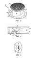
- the outlet portion 24 further includes a dome shaped perforated top plate 44 through which the bleed air is discharged into the duct 30.
- the perforated top plate 44 includes a plurality of discrete holes 46. Each hole 46 is sized to prevent the bleed air discharge from contacting the outer wall 48 of the fan duct 30. Further, each hole 46 is not perpendicular to the surface of the perforated top plate 44. Instead, each hole 46 is angled to enhance turning of the exhaust plume 27 in a circumferential direction when looking from the front or rear of the engine.
- the interior shape of the side surfaces 36 and 38, as shown in FIGS. 6 and 7 is such that the bleed air is fed to all of the holes 46.
- the perforated top plate 44 has been found to be useful in diffusing the bleed air as it travels from the inlet portion 22 to the outlet portion 24.
- the perforated top plate 44 also distributes the hot bleed discharge gasses over an area that produces an optimum plume shape and size.
- the bleed deflector of the present invention has particular utility with composite nacelles because such nacelles burn much more easily than metallic nacelles.
- the bleed deflector of the present invention is quite beneficial during idle times when compressor bleed discharge temperature is quite hot.
Landscapes
- Engineering & Computer Science (AREA)
- Chemical & Material Sciences (AREA)
- Combustion & Propulsion (AREA)
- Mechanical Engineering (AREA)
- General Engineering & Computer Science (AREA)
- Physics & Mathematics (AREA)
- Fluid Mechanics (AREA)
- Structures Of Non-Positive Displacement Pumps (AREA)
Claims (8)
- Abblasluft-Deflektor (20) für eine Gasturbinenmaschine, aufweisend:einen Einlassbereich (22) zum Empfangen von Abblasluft von einem Bereich der Maschine; undeine perforierte obere Platte (44) zum Abgeben der Abblasluft in einen Kanal (30), wobei die perforierte obere Platte (44) mit dem Einlassbereich (22) im Wesentlichen axial ausgerichtet ist;dadurch gekennzeichnet, dass er ferner Folgendes aufweist:eine aerodynamisch ausgebildete Stütze (26), die mit dem Einlassbereich (22) verbunden ist, um die perforierte obere Platte (44) auf einer Höhe über einer inneren Wand (28) des Kanals (30) zu positionieren, so dass Verdünnungsluft unterhalb der perforierten oberen Platte (44) strömt unddadurch verhindert ist, dass die Abblasluft mit der inneren Wand (28) des Kanals (30) in Berührung tritt.
- Abblasluft-Deflektor nach Anspruch 1,
wobei die obere Platte (44) kuppelförmig ausgebildet ist. - Abblasluft-Deflektor nach Anspruch 1 oder 2,
wobei die obere Platte (44) eine Mehrzahl von Öffnungen (46) aufweist, wobei jede der Öffnungen (46) in einem Winkel angeordnet ist, um mindestens eine Austrittsluftfahne innerhalb des Kanals (30) zu erzeugen. - Abblasluft-Deflektor nach Anspruch 3,
wobei jede der Öffnungen (46) derart dimensioniert ist, dass verhindert ist, dass die mindestens eine Luftfahne mit einer äußeren Wand (48) des Kanals (30) in Berührung tritt. - Abblasluft-Deflektor nach Anspruch 1 oder 2,
wobei die obere Platte (44) eine Mehrzahl von gegenüber der inneren Kanalwand (28) in einer erhöhten Position angeordneten Öffnungen (46) aufweist, um den Abblasluft-Austritt in eine Mehrzahl von einzelnen Luftfahnen zu unterteilen, wobei jede der Öffnungen (46) in einem Winkel angeordnet ist, um das Drehen der Abblasluft zum Bilden der Luftfahnen zu unterstützen. - Abblasluft-Deflektor nach Anspruch 5,
wobei jede Öffnung (46) derart dimensioniert ist, dass verhindert ist, dass die aus der oberen Platte (44) austretende Abblasluft auf eine äußere (48) und die innere Wand (28) des Kanals (30) auftrifft und dort Verbrennungen verursacht. - Abblasluft-Deflektor nach einem der vorausgehenden Ansprüche, wobei die Stütze (26) einen vorderen Rand (32), einen hinteren Rand (34) sowie zwei aerodynamisch ausgebildete Seitenflächen (36, 38) aufweist, die sich zwischen dem vorderen Rand (32) und dem hinteren Rand (34) erstrecken.
- Abblasluft-Deflektor nach Anspruch 7,
wobei die jeweiligen Seitenflächen (36, 38) nicht linear sind.
Applications Claiming Priority (2)
| Application Number | Priority Date | Filing Date | Title |
|---|---|---|---|
| US09/971,404 US6565313B2 (en) | 2001-10-04 | 2001-10-04 | Bleed deflector for a gas turbine engine |
| US971404 | 2001-10-04 |
Publications (3)
| Publication Number | Publication Date |
|---|---|
| EP1300567A2 EP1300567A2 (de) | 2003-04-09 |
| EP1300567A3 EP1300567A3 (de) | 2006-11-02 |
| EP1300567B1 true EP1300567B1 (de) | 2012-03-14 |
Family
ID=25518338
Family Applications (1)
| Application Number | Title | Priority Date | Filing Date |
|---|---|---|---|
| EP02256189A Expired - Lifetime EP1300567B1 (de) | 2001-10-04 | 2002-09-06 | Deflektor für Abblasluft einer Gasturbine |
Country Status (3)
| Country | Link |
|---|---|
| US (1) | US6565313B2 (de) |
| EP (1) | EP1300567B1 (de) |
| JP (1) | JP3851252B2 (de) |
Families Citing this family (41)
| Publication number | Priority date | Publication date | Assignee | Title |
|---|---|---|---|---|
| CA2598983C (en) | 2005-02-25 | 2014-04-01 | Volvo Aero Corporation | A bleed structure for a bleed passage in a gas turbine engine |
| GB0504272D0 (en) * | 2005-03-02 | 2005-04-06 | Rolls Royce Plc | A turbine engine and a method of operating a turbine engine |
| US7415827B2 (en) * | 2005-05-18 | 2008-08-26 | United Technologies Corporation | Arrangement for controlling fluid jets injected into a fluid stream |
| US7387489B2 (en) | 2005-10-17 | 2008-06-17 | Honeywell International Inc. | Bleed valve outlet flow deflector |
| US7946104B2 (en) * | 2006-05-12 | 2011-05-24 | Rohr, Inc. | Bleed air relief system for engines |
| US7455498B2 (en) | 2006-06-19 | 2008-11-25 | United Technologies Corporation | Slotted bleed deflector for a gas turbine engine |
| GB0614360D0 (en) * | 2006-07-20 | 2006-08-30 | Rolls Royce Plc | Aeroengine bleed valve |
| US20080044273A1 (en) * | 2006-08-15 | 2008-02-21 | Syed Arif Khalid | Turbomachine with reduced leakage penalties in pressure change and efficiency |
| US20080046407A1 (en) * | 2006-08-16 | 2008-02-21 | Microsoft Corporation | Application search interface |
| GB0616847D0 (en) | 2006-08-25 | 2006-10-04 | Rolls Royce Plc | Aeroengine bleed valve |
| US7797945B2 (en) * | 2006-09-06 | 2010-09-21 | Honeywell International Inc. | Bleed valve outlet flow deflector |
| US20090016871A1 (en) * | 2007-07-10 | 2009-01-15 | United Technologies Corp. | Systems and Methods Involving Variable Vanes |
| US8029234B2 (en) * | 2007-07-24 | 2011-10-04 | United Technologies Corp. | Systems and methods involving aerodynamic struts |
| US20090126194A1 (en) * | 2007-11-21 | 2009-05-21 | Honeywell International, Inc. | Noise attenuators and methods of manufacturing noise attenuators and bleed valve assemblies |
| US8197209B2 (en) * | 2007-12-19 | 2012-06-12 | United Technologies Corp. | Systems and methods involving variable throat area vanes |
| GB0801301D0 (en) | 2008-01-25 | 2008-03-05 | Rolls Royce Plc | Aeroengine bleed valve |
| GB2468669C (en) * | 2009-03-17 | 2013-11-13 | Rolls Royce Plc | A flow discharge device |
| GB0912171D0 (en) * | 2009-07-14 | 2009-08-26 | Rolls Royce Plc | A flow discharge device |
| GB0922425D0 (en) * | 2009-12-23 | 2010-02-03 | Rolls Royce Plc | Bleed assembly for a gas turbine engine |
| US20110265490A1 (en) * | 2010-04-30 | 2011-11-03 | Kevin Samuel Klasing | Flow mixing vent system |
| DE102010027587A1 (de) * | 2010-07-19 | 2012-01-19 | Rolls-Royce Deutschland Ltd & Co Kg | Zapfluftauslass im Nebenstromkanal eines Turbofantriebwerks |
| GB201015743D0 (en) | 2010-09-21 | 2010-10-27 | Rolls Royce Plc | Bleed valve |
| US8430202B1 (en) * | 2011-12-28 | 2013-04-30 | General Electric Company | Compact high-pressure exhaust muffling devices |
| US8511096B1 (en) | 2012-04-17 | 2013-08-20 | General Electric Company | High bleed flow muffling system |
| US9399951B2 (en) | 2012-04-17 | 2016-07-26 | General Electric Company | Modular louver system |
| US8550208B1 (en) | 2012-04-23 | 2013-10-08 | General Electric Company | High pressure muffling devices |
| US9366185B2 (en) | 2012-09-28 | 2016-06-14 | United Technologies Corporation | Flexible connection between a wall and a case of a turbine engine |
| GB201322833D0 (de) | 2013-12-23 | 2014-02-12 | Rolls Royce Plc | |
| US10443428B2 (en) * | 2014-02-19 | 2019-10-15 | United Technologies Corporation | Gas turbine engine having minimum cooling airflow |
| GB201408543D0 (en) * | 2014-05-14 | 2014-06-25 | Rolls Royce Plc | Distributor device for cooling air within an engine |
| FR3085438B1 (fr) * | 2018-08-30 | 2021-01-22 | Safran Aircraft Engines | Embouchure d'ejection d'un gaz chaud a travers une paroi de moteur d'aeronef |
| FR3087840B1 (fr) * | 2018-10-29 | 2021-01-08 | Safran Aircraft Engines | Capot de nacelle pour ensemble propulsif d'aeronef |
| US11078837B2 (en) * | 2019-02-06 | 2021-08-03 | Raytheon Technologies Corporation | Engine bleed air ducting into heat exchanger |
| FR3109174B1 (fr) * | 2020-04-10 | 2022-04-22 | Safran Aircraft Engines | Grille de conduit de décharge à canaux acoustiquement optimisée |
| CN115788673B (zh) * | 2021-09-10 | 2026-01-23 | 中国航发商用航空发动机有限责任公司 | 航空发动机的核心机及航空发动机 |
| CN113982707A (zh) * | 2021-11-04 | 2022-01-28 | 中国航发沈阳黎明航空发动机有限责任公司 | 一种航空发动机卸荷腔排气转向支板 |
| US12366202B2 (en) | 2022-01-18 | 2025-07-22 | General Electric Company | Bleed valve assemblies |
| US12320259B2 (en) | 2022-06-27 | 2025-06-03 | General Electric Company | Compact bleed valve assemblies |
| US11970969B2 (en) * | 2022-06-29 | 2024-04-30 | General Electric Company | Compressor bypass bleed system for a ducted fan engine |
| US12049845B2 (en) | 2022-08-09 | 2024-07-30 | General Electric Company | Variable bleed valves with struts for aerodynamic stability |
| US12180890B1 (en) | 2023-06-23 | 2024-12-31 | General Electric Company | Variable bleed valve assemblies |
Family Cites Families (5)
| Publication number | Priority date | Publication date | Assignee | Title |
|---|---|---|---|---|
| US4463552A (en) * | 1981-12-14 | 1984-08-07 | United Technologies Corporation | Combined surge bleed and dust removal system for a fan-jet engine |
| US4537277A (en) | 1982-12-03 | 1985-08-27 | The Secretary Of State For Defence In Her Britannic Majesty's Government Of The United Kingdom Of Great Britain And Northern Ireland | Silencer for high velocity gas flow |
| US5160241A (en) * | 1991-09-09 | 1992-11-03 | General Electric Company | Multi-port air channeling assembly |
| DE69912488T2 (de) * | 1998-02-13 | 2004-08-12 | Pratt & Whitney Canada Corp., Longueuil | Gasturbine |
| DE19959596A1 (de) * | 1999-12-10 | 2001-06-13 | Rolls Royce Deutschland | Abblaseventil eines Verdichters, insbesondere für ein Zweistrahl-Flugtriebwerk |
-
2001
- 2001-10-04 US US09/971,404 patent/US6565313B2/en not_active Expired - Lifetime
-
2002
- 2002-09-06 EP EP02256189A patent/EP1300567B1/de not_active Expired - Lifetime
- 2002-10-03 JP JP2002290990A patent/JP3851252B2/ja not_active Expired - Fee Related
Also Published As
| Publication number | Publication date |
|---|---|
| US6565313B2 (en) | 2003-05-20 |
| EP1300567A3 (de) | 2006-11-02 |
| US20030068223A1 (en) | 2003-04-10 |
| JP2003161167A (ja) | 2003-06-06 |
| JP3851252B2 (ja) | 2006-11-29 |
| EP1300567A2 (de) | 2003-04-09 |
Similar Documents
| Publication | Publication Date | Title |
|---|---|---|
| EP1300567B1 (de) | Deflektor für Abblasluft einer Gasturbine | |
| US5498133A (en) | Pressure regulated film cooling | |
| US4537277A (en) | Silencer for high velocity gas flow | |
| CA2536859C (en) | Bell-shaped fan cooling holes for turbine airfoil | |
| CA2534061C (en) | High efficiency fan cooling holes for turbine airfoil | |
| EP0502924B1 (de) | Doppeltströmungsschalldämpfer für ein turbinentriebwerk | |
| US8931284B2 (en) | Flow discharge device | |
| US4979587A (en) | Jet engine noise suppressor | |
| US6431832B1 (en) | Gas turbine engine airfoils with improved cooling | |
| EP1870580A2 (de) | Abluftdeflektor für einen Gasturbinenmotor | |
| EP1507121A3 (de) | Brennkammerdom für eine Gasturbine mit verbesserter Ablenkungsplatte | |
| CA2392577A1 (en) | Gas turbine stationary blade | |
| EP0340149A1 (de) | Staubabscheider für eine luftgekühlte Schaufel | |
| WO1995019289A1 (en) | Engine exhaust gas deflection system | |
| CA2198225A1 (en) | Gas turbine blade with cooled platform | |
| EP1397586A1 (de) | Abgasströmungsführung zur reduktion von luftstrahllärm | |
| JP2003214117A (ja) | 地上又は航空ガスタービン用ディフューザ | |
| WO2002097870A3 (en) | Diffuser and rapid cycle chamber | |
| CA2528049A1 (en) | Airfoil platform impingement cooling | |
| CA2206038A1 (en) | Air diffuser apparatus | |
| CA2383463A1 (en) | Methods and apparatus for cooling gas turbine engine combustors | |
| US5387081A (en) | Compressor diffuser | |
| EP1498661A3 (de) | Verfahren und Vorrichtung zur Kühlung einer Gasturbinenbrennkammer | |
| GB2132269A (en) | Silencer for high velocity gas flow | |
| US5085039A (en) | Coanda phenomena combustor for a turbine engine |
Legal Events
| Date | Code | Title | Description |
|---|---|---|---|
| PUAI | Public reference made under article 153(3) epc to a published international application that has entered the european phase |
Free format text: ORIGINAL CODE: 0009012 |
|
| AK | Designated contracting states |
Designated state(s): AT BE BG CH CY CZ DE DK EE ES FI FR GB GR IE IT LI LU MC NL PT SE SK TR Kind code of ref document: A2 Designated state(s): AT BE BG CH CY CZ DE DK EE ES FI FR GB GR IE IT LI LU MC NL PT SE SK TR |
|
| AX | Request for extension of the european patent |
Extension state: AL LT LV MK RO SI |
|
| PUAL | Search report despatched |
Free format text: ORIGINAL CODE: 0009013 |
|
| AK | Designated contracting states |
Kind code of ref document: A3 Designated state(s): AT BE BG CH CY CZ DE DK EE ES FI FR GB GR IE IT LI LU MC NL PT SE SK TR |
|
| AX | Request for extension of the european patent |
Extension state: AL LT LV MK RO SI |
|
| 17P | Request for examination filed |
Effective date: 20070319 |
|
| AKX | Designation fees paid |
Designated state(s): DE FR GB |
|
| 17Q | First examination report despatched |
Effective date: 20071031 |
|
| GRAP | Despatch of communication of intention to grant a patent |
Free format text: ORIGINAL CODE: EPIDOSNIGR1 |
|
| RIN1 | Information on inventor provided before grant (corrected) |
Inventor name: MIGLIARO, EDWARD F. Inventor name: NIKKANEN, JOHN P. Inventor name: AVIS, THOMAS B. Inventor name: ZYSMAN, STEVEN H. |
|
| GRAS | Grant fee paid |
Free format text: ORIGINAL CODE: EPIDOSNIGR3 |
|
| GRAA | (expected) grant |
Free format text: ORIGINAL CODE: 0009210 |
|
| AK | Designated contracting states |
Kind code of ref document: B1 Designated state(s): DE FR GB |
|
| REG | Reference to a national code |
Ref country code: GB Ref legal event code: FG4D Ref country code: DE Ref legal event code: R081 Ref document number: 60242382 Country of ref document: DE Owner name: UNITED TECHNOLOGIES CORP. (N.D.GES.D. STAATES , US Free format text: FORMER OWNER: UNITED TECHNOLOGIES CORP. (N.D.GES.D. STAATES DELAWARE), HARTFORD, CONN., US |
|
| REG | Reference to a national code |
Ref country code: DE Ref legal event code: R096 Ref document number: 60242382 Country of ref document: DE Effective date: 20120503 |
|
| PLBE | No opposition filed within time limit |
Free format text: ORIGINAL CODE: 0009261 |
|
| STAA | Information on the status of an ep patent application or granted ep patent |
Free format text: STATUS: NO OPPOSITION FILED WITHIN TIME LIMIT |
|
| 26N | No opposition filed |
Effective date: 20121217 |
|
| REG | Reference to a national code |
Ref country code: DE Ref legal event code: R097 Ref document number: 60242382 Country of ref document: DE Effective date: 20121217 |
|
| REG | Reference to a national code |
Ref country code: FR Ref legal event code: ST Effective date: 20130531 |
|
| PG25 | Lapsed in a contracting state [announced via postgrant information from national office to epo] |
Ref country code: FR Free format text: LAPSE BECAUSE OF NON-PAYMENT OF DUE FEES Effective date: 20121001 |
|
| REG | Reference to a national code |
Ref country code: DE Ref legal event code: R082 Ref document number: 60242382 Country of ref document: DE Representative=s name: SCHMITT-NILSON SCHRAUD WAIBEL WOHLFROM PATENTA, DE |
|
| REG | Reference to a national code |
Ref country code: DE Ref legal event code: R082 Ref document number: 60242382 Country of ref document: DE Representative=s name: SCHMITT-NILSON SCHRAUD WAIBEL WOHLFROM PATENTA, DE Ref country code: DE Ref legal event code: R081 Ref document number: 60242382 Country of ref document: DE Owner name: UNITED TECHNOLOGIES CORP. (N.D.GES.D. STAATES , US Free format text: FORMER OWNER: UNITED TECHNOLOGIES CORPORATION, HARTFORD, CONN., US |
|
| PGFP | Annual fee paid to national office [announced via postgrant information from national office to epo] |
Ref country code: DE Payment date: 20190820 Year of fee payment: 18 |
|
| PGFP | Annual fee paid to national office [announced via postgrant information from national office to epo] |
Ref country code: GB Payment date: 20190820 Year of fee payment: 18 |
|
| REG | Reference to a national code |
Ref country code: DE Ref legal event code: R119 Ref document number: 60242382 Country of ref document: DE |
|
| GBPC | Gb: european patent ceased through non-payment of renewal fee |
Effective date: 20200906 |
|
| PG25 | Lapsed in a contracting state [announced via postgrant information from national office to epo] |
Ref country code: DE Free format text: LAPSE BECAUSE OF NON-PAYMENT OF DUE FEES Effective date: 20210401 |
|
| PG25 | Lapsed in a contracting state [announced via postgrant information from national office to epo] |
Ref country code: GB Free format text: LAPSE BECAUSE OF NON-PAYMENT OF DUE FEES Effective date: 20200906 |